
Related Manuals for THORLABS TXP Series


Summary of Contents for THORLABS TXP Series
- Page 1 Operation Manual Thorlabs TXP Series Laser Current and Temperature Controller ITC5000 2004...
- Page 2 Version: 2.10 Date: 11-Oct-04 © Copyright 2004, Thorlabs GmbH...
-
Page 3: Table Of Contents
Contents Page General description 1.1 Safety 1.2 Warranty 1.3 Features 1.3.1 Safety measures for the laser diode and the TEC element 1.3.2 Ordering Codes: 1.3.3 General functions 1.4 Technical data ITC5000 Series 1.4.1 Technical Data ITC5022 1.4.2 Technical Data ITC5052 1.4.3 Technical Data ITC5102 1.5 Operating elements at the front of the card... - Page 4 3.2 Menu items 3.2.1 The ‘File’ menu 3.2.2 The ‘Connection’ menu 3.2.3 The ‘Setup’ menu 3.2.4 The cards menu 3.2.5 The ‘Preferences’ menu Service and Maintenance 4.1 Troubleshooting 4.2 Service Listings 5.1 List of Acronyms 5.2 List of figures 5.3 List of possible status messages 5.4 Addresses...
- Page 5 Therefore, please let us know about possible criticism or ideas. We and our international partners are looking forward to hearing from you. Thorlabs GmbH This part of the instruction manual contains every specific information on how to handle and use a ITC5000 mainframe. A general description is followed by explanations of how to operate the unit remotely.
-
Page 7: General Description
1.1 Safety 1 General description 1.1 Safety Attention All statements regarding safety of operation and technical data in this instruction manual will only apply when the unit is operated correctly. Laser modules or coding sockets may only be installed or removed with the corresponding diode controller switched off. -
Page 8: Warranty
1.2 Warranty 1.2 Warranty Thorlabs GmbH warrants material and production of the ITC5000 for a period of 24 months starting with the date of shipment. During this warranty period Thorlabs GmbH will see to defaults by repair or by exchange if these are entitled to warranty. -
Page 9: Features
1.3 Features 1.3 Features 1.3.1 Safety measures for the laser diode and the TEC element To protect the connected laser diodes and the TEC elements the combi controller ITC5xxx contains the following protection circuits: • Softstart when switching on the laser diode current Protection against capacitive and inductive parasitic elements (switching peaks). -
Page 10: Ordering Codes
• Action check After power up the combi modules are in LASER OFF mode. • LabVIEW®- and LabWindows/CVI®-driver ® For the TXP-series cards Thorlabs supplies LabVIEW - and ® LabWindows/CVI -drivers for MS Windows 32, MSVC and Borland-C. -
Page 11: General Functions
1.3 Features 1.3.3 General functions The combi modules ITC5xxx are bipolar current sources for laser diodes combined with a thermoelectric controller. The different module types operate the same way, they only differ in maximum current, resolution and accuracy. The combi modules ITC5xxx contain a transimpedance amplifier input for the monitor diode (input impedance 0 Ω). -
Page 12: Technical Data Itc5000 Series
1.4 Technical data ITC5000 Series 1.4 Technical data ITC5000 Series (All technical data are valid at 23 ± 5°C and 45 ±15% humidity) Common technical data: Safety functions Laser Diode: Softstart Short Circuit when off Laser current limit Global interlock Individual Interlock Switch off when open Overtemperature protection... - Page 13 1.4 Technical data ITC5000 Series TEC Current Limit Adjustment Range 0 … > 1.5 A Resolution 0.5 mA Accuracy ± 0.02 A Thermistor Sensor Operating Range 0.2 … 40 kΩ 0.8 Ω Resolution ± 10 Ω Accuracy 1 Ω Stability (60 min) Control Loop Digitally controlled analog PID;...
-
Page 14: Technical Data Itc5022
1.4 Technical data ITC5000 Series 1.4.1 Technical Data ITC5022 Laser Current Range 0 … > 200 mA Compliance Voltage > 2.5 V Setting Resolution 4 µA Accuracy ± 0.05 % (100 µA) Noise < 2µA Ripple < 0.5 µA Transients (µP) <... -
Page 15: Technical Data Itc5052
1.4 Technical data ITC5000 Series 1.4.2 Technical Data ITC5052 Laser Current Range 0 … > 500 mA Compliance Voltage > 2.5 V Setting Resolution 8 µA Accuracy ±0.05 % (0.25 mA) Noise < 5 µA Ripple < 0.5 µA Transients (µP) <... -
Page 16: Technical Data Itc5102
1.4 Technical data ITC5000 Series 1.4.3 Technical Data ITC5102 Laser Current Range 0 … > 1 A Compliance Voltage > 2.5 V Setting Resolution 20 µA Accuracy ±0.1 % (1 mA) Noise < 10 µA Ripple < 0.5 µA Transients (µP) <... -
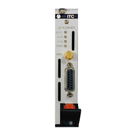
Page 17: Operating Elements At The Front Of The Card
Mounting screw 1.6 Installing and removing cards The Thorlabs TXP series mainframes are ‘Hot-Plug capable’, that means you do not have to switch off the mainframe while exchanging cards: • Loosen the two mounting screws on top and below the ejector handle •... -
Page 18: Connecting Components
1.7 Connecting components 1.7 Connecting components Mostly the following components are installed together with the laser: • Laser diode • Monitor diode • TEC element for chip temperature control • Temperature sensor (thermistor) The laser diode and the TEC element are always sourced relative to ground by the combi module. -
Page 19: Pin Assignment Itc5Xxx
1.7 Connecting components 1.7.1 Pin assignment ITC5xxx 9-10-11-12-13-14-15 1-2-3-4-5-6-7-8 Figure 1 ITC5xxx-15pin D-SUB I/O jack (female) Name Function TEC- TEC minus (ground) TEC + TEC plus UTEC + TEC Voltage measurement + UTEC - TEC Voltage measurement - Thermistor ground Thermistor Laser diode anode LGND... - Page 20 1.7 Connecting components We recommend to use separate lines drilled in pairs (twisted pair) in a common shield for laser diode current, monitor diode current, TEC voltage and laser voltage measurement. The shield has to be connected to ground (pin 3). If an external monitor diode is used, it must be connected by a coaxial cable with the outer conductor (shield) to pin 2 and the inner conductor to pin 4.
-
Page 21: Connecting The Laser Diode
1.7 Connecting components 1.7.2 Connecting the Laser diode Connect laser and monitor diode to the connector of the ITC5xxx. The wires for voltage measurement of the laser diode (pin 12 and pin 9) should be connected as close as possible to the laser diode to avoid measurement errors. The ground conductor of the monitor diode (pin 2) may be connected to the ground conductor of the laser diode (pin 3). -
Page 22: Connecting The Monitor Diode
1.7 Connecting components 1.7.3 Connecting the Monitor diode 0 … +4V PD_BIAS (4) PD_GND (2) PD_BIAS (4) PD_GND (2) 0 … -4V Cathode Grounded (CG) Anode grounded (AG) Monitor Diode with Bias PD_GND (2) PD_BIAS (4) PD_BIAS (4) PD_GND (2) Cathode Grounded (CG) Anode grounded (AG) Monitor Diode without Bias... -
Page 23: Connecting Interlock And Status Led
1.7 Connecting components 1.7.4 Connecting interlock and status LED Pin 1 and pin 5 of the connector jack serve as safety connectors to determine whether the current output for the laser diode may be switched on. A short-circuit or at least a low resistance (R<430 Ω) must be maintained between the two pins. With the contacts open or resistance too high the current module cannot be switched on. -
Page 24: Connecting The Thermistor
1.7 Connecting components 1.7.5 Connecting the thermistor The thermistor is connected between pin 14 and pin 15, no polarity is given. Figure 4 Connecting the thermistor ITC5000 / page 18... -
Page 25: Connecting The Tec Element
1.7 Connecting components 1.7.6 Connecting the TEC element Connect the TEC element to pins 7 and 6 (+) and the pins 8 and 13 for (-). Figure 5 Connecting the TEC Attention An reverse poled TEC element may lead to thermal runaway and destruction of the connected components. -
Page 26: Getting Started
2.1 Preconditions 2 Getting Started This section gives a quick introduction how to operate the ITC5000. 2.1 Preconditions 1. Precondition: you have installed and initialized the connection between the TXP and your PC according to the manual of the corresponding TXP main- frame. -
Page 27: The Graphics User Interface (Gui)
2.2 The Graphics User Interface (GUI) 2.2 The Graphics User Interface (GUI) 2.2.1 Start the GUI To start the graphics user interface you have two possibilities: 1. Use the TXP Explorer or 2. Directly start the program: TXP_ITC.exe (double-click on 1) Start the TXP-Explorer and connect to the desired mainframe . - Page 28 2.2 The Graphics User Interface (GUI) Figure 7 The ITC5000 GUI Surface Alternatively: 2) Start TXP_ITC:exe directly. In this case you must connect to the desired card in the corresponding mainframe through the ‘Connection’ menu. Clicking ‘Connect’ opens the selection window for the mainframe IP-address (see Figure 8).
- Page 29 2.2 The Graphics User Interface (GUI) Figure 8 Select the IP-Address Figure 9 Select Port number and Timeout ITC5000 / page 23...
-
Page 30: Set Limit Values
2.2 The Graphics User Interface (GUI) Figure 10 The card selection window Attention Before switching on any currents, you must properly configure your settings: Current Limit values, Laser diode polarity, Operating mode, Photodi- ode polarity and a possible bias. Wrong settings can destroy your Laser Diode! 2.2.2 Set limit values Before starting any further operation of the card, you should set the limit values to not endanger your laser diode! -
Page 31: Set The Laser- And Photodiode Polarities And The Operating Mode
2.2 The Graphics User Interface (GUI) Unlock the two fields for TEC Current limit and Laser Diode Current limit, and enter the maximum allowable values for both (please refer to the data sheet of your laser diode / laser diode mount). Do not forget to lock these fields again. 2.2.3 Set the Laser- and Photodiode polarities and the operating mode In the drop-down menu ‘Setup’, select ‘LD Current Control’. -
Page 32: Change The Temperature Control Settings
2.2 The Graphics User Interface (GUI) To obtain a correct power display, enter also the given calibration factor of the photo diode. Now set the intended operating mode, Constant Power (CP) or constant Current (CC). 2.2.4 Change the temperature control Settings In the drop-down menu ‘Setup’, select ‘Temperature Control’. - Page 33 2.2 The Graphics User Interface (GUI) Now you are ready to operate your laser diode. Enter the desired values for laser current or power and for the operating temperature. Then you can switch on the TEC and the laser diode. ITC5000 / page 27...
-
Page 34: List Of All Operating Items
3.1 Operating elements in the main window 3 List of all Operating items 3.1 Operating elements in the main window ITC5000 / page 28... -
Page 35: Select The Display Variables
3.1 Operating elements in the main window 3.1.1 Select the Display Variables In the TEC part of the main-screen as well as in the Laser Diode part, you can simultaneously select and watch two operating parameters. For the TEC: • The thermistor temperature in °C, recalculated from its resistance •... -
Page 36: Set The Limit Values
3.1 Operating elements in the main window For the set temperature: • Display and entry field in kΩ, • Display and entry field in °C • Display and entry field in K. The values in °C and K are calculated from or recalculated to the ‘real’ variable, the resistance of the thermistor in kΩ. - Page 37 3.1 Operating elements in the main window PID adjustment Temperature control loops are comparatively slow with control oscillations in the Hertz range. The PID adjustment will optimize the dynamic behavior. With the ITC5000 the three parameters P, I and D can be set independently. To ease the use of these items, two predefined settings are stored and can be recalled by a single click: standard settings for butterfly / DIL-lasers and settings for TO mounted laser diodes.
-
Page 38: Modulation Setup
3.1 Operating elements in the main window D-share • Change repeatedly between set temperatures of 18 °C and 22 °C while observing again the settling behavior of the actual temperature. Increase the D-share gradually. Higher values will decrease the amplitude of the overshoots. -
Page 39: Switching On And Off
3.1 Operating elements in the main window It must be reminded, that this scale depends on the absolute settings of laser diode current or power. 100% modulation means that neither the laser extinguishes, nor the set maximum value is overdriven. So 100% modulation depth is only reachable at about 60% f.s. -
Page 40: The Status Messages Field
OK. Together with the error message, an error number is given. Please refer to this error number when consulting the Thorlabs technical hotline! Messages in red are more important than those in black. If the condition producing this status message has vanished, e.g. if the interlock has been closed in-between, the error message disappears. -
Page 41: Menu Items
3.2 Menu items 3.2 Menu items 3.2.1 The ‘File’ menu • ‘Load Setup’: All settings you make with this ITC5000 card can be stored in a file and reloaded any time. If this file is loaded by another card as it was stored from, you will get a warning message or even an error message if the settings are physically impossible for this card. -
Page 42: The 'Setup' Menu
3.2 Menu items Enter the IP Address of your TXP mainframe (this address is given to the TXP in the initialization process with the TXP-Administrator program) and if necessary (ask your system operator) also the port number and a timeout value under ‘Advanced’: The timeout value is the wait-time after which the program card yields a connection error if the ITC does not respond. - Page 43 3.2 Menu items 3.2.3.1 LD Current Control Setup Figure 11 Laser Diode Setup Menu Select the laser diode polarity between AG (Anode Grounded) or CG (cathode Grounded). Select the photo diode polarity between AG (Anode Grounded) or CG (cathode Grounded). Select the operating mode between Constant Power and Constant Current mode.
- Page 44 3.2 Menu items 3.2.3.2 Temperature Control Setup Depending on the thermistor used, the calibration coefficients are given in exponential form or as ‘Steinhart-Hart’-Parameters. Select the corresponding form and enter the calibration coefficients (given in the data sheet of the thermistor / Laser Diode).
- Page 45 3.2 Menu items 3.2.3.3 Temperature Window Setup The ITC5000 allows you to set a temperature protection window. This function switches off your laser diode current, if the temperature leaves this predefined window. To enter new settings and activate the window function both laser current and TEC current must be switched off.
-
Page 46: The Cards Menu
3.2 Menu items 3.2.4 The cards menu The only item in this menu is to give you some more detailed information about the corresponding card. 3.2.5 The ‘Preferences’ menu The ‘preferences’ menu contains one item: ‘Communication’, which allows to define the refreshing rate of all information retrieved from the card. - Page 47 3.2 Menu items Depending on the bandwidth and reliability of your connection between TXP and PC, you can select update rates from 10 seconds down to 0.3 s. ITC5000 / page 41...
-
Page 49: Service And Maintenance
4.1 Troubleshooting 4 Service and Maintenance 4.1 Troubleshooting Card does not work at all : Look if the Card is inserted properly into the TXP mainframe and the ejector handle has snapped into its position. Look if the mainframe is powered up (does any LED light up) Try to insert the card in another slot. -
Page 50: Service
4.2 Service 4.2 Service In normal operation the ITC5000 card does not need any service. If highest precision of the measurements is vital for you, you should have recalibrated the ITC5000 every two years. You can see the due date of calibration in the card info-menu of the card driver (refer to 3.2.4, “The cards menu”). -
Page 51: Listings
5.1 List of Acronyms 5 Listings 5.1 List of Acronyms The following acronyms and abbreviations are used in this manual: Analog to Digital Converter ASCII American Standard Code for Information Interchange CLeaR Carriage Return Digital to Analog Converter D-Share Differential share IEEE Institute for Electrical and Electronic Engineering I-Share... -
Page 52: List Of Figures
5.2 List of figures 5.2 List of figures Figure 1 ITC5xxx-15pin D-SUB I/O jack (female) Figure 2 Connecting the Laserdiode Figure 3 Connecting the Monitor Diode Figure 4 Connecting the thermistor Figure 5 Connecting the TEC Figure 6 The TXP Explorer Window Figure 7 The ITC5000 GUI Surface Figure 8... -
Page 53: List Of Possible Status Messages
TXP. “Critical Card Temperature reached” Informs about the temperature of the card reaching its limit Internal error, please contact Thorlabs GmbH “Supply Voltage Failed” Close the global interlock line or put the short “Global Interlock Open”... -
Page 54: Addresses
5.4 Addresses 5.4 Addresses For technical support or sales inquiries, please visit us at www.thorlabs.com/contact for our most up-to- date contact information. USA, Canada, and South America UK and Ireland Thorlabs, Inc. Thorlabs Ltd. sales@thorlabs.com sales.uk@thorlabs.com techsupport@thorlabs.com techsupport.uk@thorlabs.com Europe Scandinavia...
Need help?
Do you have a question about the TXP Series and is the answer not in the manual?
Questions and answers