Table of Contents
Advertisement
Advertisement
Table of Contents

Related Manuals for THORLABS TED4015


Summary of Contents for THORLABS TED4015
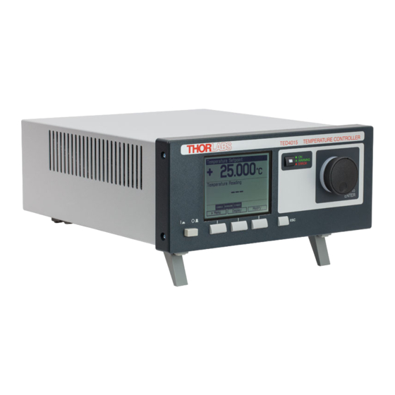
- Page 1 Temperature Controller TED4015 Operation Manual 2017...
- Page 2 Version: Date: 06-Oct-2017 Item No.: M0009-510-311 Copyright Copyright © 2017 Thorlabs...
-
Page 3: Table Of Contents
1.3 Ordering Codes and Accessories 2 Getting Started 2.1 Preparation 2.2 Operating Elements 2.3 First Operation 2.4 System Preferences 3 Operating the TED4015 Series 3.1 Connecting Components 3.1.1 Pin Assignment of the TEC Output Jack 3.1.2 Connecting a TEC Element 3.1.3... - Page 4 5.4 Troubleshooting 6 Appendix 6.1 Technical Data 6.2 Setup and Function of a Temperature Controller 6.3 PID Controller Theory 6.4 Menu Structure Overview 6.5 Factory Settings for Thorlabs TED4015 Controllers 6.6 Error Messages 6.6.1 LED Status Messages 6.6.2 Status Indicators 6.6.3...
-
Page 5: Foreword
Paragraphs preceeded by this symbol explain hazards that could damage the instrument and the connected equipment or may cause loss of data. Note This manual also contains "NOTES" and "HINTS" written in this form. Please read these advices carefully! Copyright © 2017 Thorlabs... -
Page 6: General Information
TED4015 1 General Information This part of the operation manual contains specific information on how to operate a TED4015 Temperature Controller. A general description is followed by explanations of how to operate the unit manually. The instrument provides a USB 2.0 Full Speed interface according to the USB 2.0 specification, the USBTMC specification and the USBTMC USB488 specification. - Page 7 1 General Information Attention Prior to applying power to the TED4015, make sure that the protective conductor of the 3 conductor mains power cord is correctly connected to the protective earth ground con- tact of the socket outlet! Improper grounding can cause electric shock resulting in dam-...
-
Page 8: Protection Of The Tec Element
Over-temperature protection Protection against malfunction caused by internal overheating of the controller. Defined states after switch-on When switching on the TED4015 Temperature Controller with the mains switch the output is al- ways switched off. Mains filter Protection against line bursts or transients. -
Page 9: Ordering Codes And Accessories
Short description Thermoelectric Temperature Controller, TEC current range 0 ... ± 15 A TED4015 Shielded cable to connect the TED4015 Temperature Controller to a CAB4000 Thorlabs LM14S2, LDM21 or TCLDM9 Laser Diode Mount (male 17W2 mixed DSUB connector to female 9 pin DSUB connector). The rated TEC-Current is 5A. -
Page 10: Getting Started
1 Series 4000 instrumentation CD (containing manuals, drivers, tools and software) · 1 CAB4000 shielded cable to connect the TEC controller to a Thorlabs LM14S2, LDM21 or TCLDM9 laser diode mount (male17W2 mixed DSUB connector to female 9 pin DSUB connector), rated TEC current 5A ·... -
Page 11: Operating Elements
Line switch (On/Off) LC display, 320x240 Pixel Softkeys for menu navigation Escape key On/Off button for the TEC output with TEC ON LED (green) and ERROR LED (red) Adjustment knob to change set values, push to enter Copyright © 2017 Thorlabs... - Page 12 TEC OUTPUT perature sensors USB connector 4 mm banana jack for chassis ground MiniDin-6 jack for 4x digital I/O, I/O supply voltage (internal DIGITAL I/O +12 V) and GND LINE IN Mains connector and fuse holder Copyright © 2017 Thorlabs...
-
Page 13: First Operation
Replacing the mains fuses). The TED4015 is immediately ready to use after turning on. The rated accuracy is reached, however, after a warming-up time of approx. 30 minutes. After switching on the unit, the graphics display will show the device status, followed by the measurement screen. - Page 14 Enabled: Firmware can be updated at any time. Enabled once: Firmware can be updated once, afterwards this setting changes to disabled. Disabled: Firmware update is inhibited (default setting). For more information please refer to section Firmware Update. Copyright © 2017 Thorlabs...
-
Page 15: Operating The Ted4015 Series
Ground, otherwise the electronic circuit will be damaged! Attention The maximum TEC output current for the TED4015 series is 15A. Use only the specified connector type: 17W2 mixed DSUB plug with high power contacts A1 and A2 rated for at least 15A current. -
Page 16: Connecting A Tec Element
3.1.2 Connecting a TEC Element Attention The TEC element output of the TED4015 is a ground-free output. Do not connect the TEC ele- ment pins to any grounded pins (3, 5, 6, 12, 15) or to case ground, otherwise the electronic cir- cuit will be damaged. -
Page 17: Connecting A Temperature Sensor
3 Operating the TED4015 Series 3.1.3 Connecting a Temperature Sensor The temperature controller in the TED4015 can be used with the following temperature sensors: NTC thermistor, AD590, AD592, LM35, LM335, LM235, LM135, PT100, and PT1000. The setting and measurement range of thermistors is 100 Ω to 100 kΩ (Low range) and 1 kΩ to 1 MΩ... -
Page 18: Current Temperature Sensors Ad590 Or Ad592
For optimum performance, use a separate wire for each pin of the DSUB connector and connect the corresponding wires only at the PT100 or PT1000, as close as possible to the sensor (see Figure 13). Copyright © 2017 Thorlabs... -
Page 19: Setting Up The Tec Voltage Measurement
(total resistance <430 ). When this “interlock” connection is opened, the TED4015 switches off the TEC output current automatically. If the TEC output was off, it cannot be switched on and an error message “TEC cable connection fault” appears. -
Page 20: Tec Control Outputs
LDC200C series laser driver. Simply connect the corresponding plug of the laser driver to this output of the TED4015. The laser will be switched off if the laser temperature moves out of the temperature window. Further details can be found in the operation manual of the respective laser driver. -
Page 21: Power-Up
Switch into the menu by pressing the Menu button or the ESC key. In the TED4015 menu you can change different TED4015 settings described in the following chapters. For a complete menu item listing, please refer to chapter Menu structure overview. -
Page 22: Tec Source Setup
3.3 TEC Source Setup Setting the operating mode: In the TEC Source Setup menu, the temperature controller operating mode of your TED4015 can be changed. It can be shifted between Current Source mode and Constant Temperature mode. In Current Source mode, an internal constant current loop is closed, and the TEC output current can be set in Ampere. -
Page 23: Temperature Sensor Setup
Voltage sensor, 10 mV/K, 0V at 0 K, means also LM235 / LM135 Confirm your choice with Done or by pressing the adjustment knob again. For IC sensors, the calculation coefficients are predetermined by your TED4015: 1µA/K for the current sensors AD59x, 10mV/°C for LM35 and 10mV/K for LMx35. - Page 24 ±10 °C. Use a calibrated thermometer to verify the real sensor temperature. From this, subtract the temperature displayed by the TED4015 (take care of the proper signs). Enter the result as Sensor Offset in the Temperature Sensor Settings Menu. The displayed actual tem- perature will be shifted by this amount and will give you an improved absolute accuracy.
-
Page 25: Thermistor Settings
3 Operating the TED4015 Series 3.5 Thermistor Settings In Thermistor Settings menu, the parameters for a thermistor temperature calculation may be set, if a thermistor is used as temperature sensor. You can choose between two calculation methods, Exponential or Steinhart-Hart. The paramet- ers for the respective method can be set in the two additional menu items as shown below: For the Exponential Method, the required parameters are R0, T0 and β. -
Page 26: Pid Control Loop
By setting the control loop parameters of the PID control loop manually, the temperature con- troller of the TED4015 can be adapted to the most different thermal loads. Two different ways are possible to find the optimal parameters. A PID Auto-Tune function can... - Page 27 3 Operating the TED4015 Series Note The settling behavior may be additionally observed at the DEVIATION OUT jack (R14, section Operating elements at the rear panel) by means of an oscillo-scope (please refer to section TEC control outputs). Switch on the TEC output with the switch " TEC ON" (F6, see section...
- Page 28 Due to the disabled Integral constant, a temperature deviation may remain. Integral (I) parameter: Change again repeatedly between set temperatures ±1...2°C around your desired target tem- perature. Increase the I parameter gradually by turning the adjustment knob (F8) clockwise. Copyright © 2017 Thorlabs...
- Page 29 3 Operating the TED4015 Series Higher values will accelerate the settling to the set temperature. To high values will increase the amplitude and number of overshoots or will even make the system instable. The I parameter is set correctly when the actual temperature reaches the set temperature in a short time with a minimum of overshoots.
-
Page 30: Pid Auto Tune
- You already finished a PID Auto-Tuning successfully before - You didn’t change the PID parameters by hand in the meantime - You didn’t unplug the cable between the TED4015 and your thermal setup (e.g. changing the mount). To save time, the new quick PID Auto-Tune process tries only to readjust the PID parameters calculated before. - Page 31 3 Operating the TED4015 Series When you found the ideal PID parameters for your system, you can save them together with many other settings (e.g. temperature set point, current limit …) into one of the eight memory locations (see section Saving and restoring setups).
-
Page 32: Temperature Protection
TED4015 3.8 Temperature Protection The TED4015 temperature controller provides an adjustable Temperature Window to monitor the correct function of the temperature control. The display shows a “plus / minus“ value, so if you select i.e. 5 °C, the window will reach from 5 °C below the temperature setpoint to 5 °C above the temperature setpoint. -
Page 33: Display Configuration
3 Operating the TED4015 Series 3.9 Display Configuration The display can be configured to show two, four or six values on the screen. Factory setting is the two value screen. You can select your favored measurement screen by pressing the Display button or in the Dis- play Configuration menu. -
Page 34: Settings Memories
At the positions 1 … 3, the parameters (for a temperature setpoint of about 25°C) are pre- saved for the Thorlabs laser mounts. The parameter sets # 4…8 can be used to save your per- sonal setups. If more space is required, and you don't need the pre-saved parameter sets # 1…... - Page 35 3 Operating the TED4015 Series Via Recall Memory Settings you can load a saved laser setup. Note that this will overwrite your currently used instrument settings. Before recalling data from the memory, the laser and TEC outputs must be switched off (if on)
-
Page 36: Digital I/O Ports
TED4015 3.11 Digital I/O ports The tempererature controllers of the TED4015 series have a very versatile digital port providing four separately configurable Input / Output lines. This feature allows control of external circuitry from the unit, or control of the unit from external circuitry (via PC software). Figure 58 shows the... - Page 37 3 Operating the TED4015 Series I/O port source operation In above circuit, the output drives an optocoupler in source operation. This component may be replaced by a LED or a switching transistor. To switch the connected device to on-state, the output level of the digital I/O line must be set HIGH.
- Page 38 For enhanced controlling, please use the remote control interface from an external PC or Laptop. See the Thorlabs “Series 4000 Programmers Reference Manual” on the included “Ser- ies 4000 Instrumentation CD”.
-
Page 39: Systems Preferences
3 Operating the TED4015 Series 3.12 Systems Preferences The System Preferences menu allows to select different settings concerning your TED4015 system configuration, including Message Handling, Display Brightness, Display Contrast, Sound Signals, and Update Capability. For detailed explanations please see section Getting Started - System Preferences. -
Page 40: Computer Interface
Manual for a detailed description of the instrument's command set. When receiving a command, the TED4015 will enter its Remote mode.This will be indicated by the REMOTE Symbol in the Status Bar. The right softkey (F4) will serve as a Local button, which switches back from Remote mode to Local operations mode. -
Page 41: Instrument Driver Installation
PC on which you are performing the installation. After successfully installing the drivers connect the TED4015 to a USB port of your PC. The PC will find a test and measurement device. Please follow the instructions of the dialog screens and allow the installation. -
Page 42: Firmware Update
Firmware upgrades can be accomplished by the user via the USB interface using the software "Thorlabs DFU Wizard". NOTE To install the Thorlabs DFU wizard successfully, you must have Administrator privileges on the PC, and the instrument must be powered down or disconnected from the USB. Follow the instructions below to upgrade your instrument: ·... -
Page 43: Maintenance And Repair
75% Isopropyl Alcohol solution for more efficient cleaning. 5.2 Line Voltage Settings The TED4015 temperature controller operates from line voltages 100 ... 120 V AC and 200 ... 240 V AC ±10%. The line frequency range is 50 ... 60 Hz, thus it can be operated worldwide without any adjustment or voltage setting. -
Page 44: Replacing The Mains Fuses
3. Replace the defective fuses (R11). We recommend changing both fuses, even if only one fuse has opened. Press in the fuse holder until locked on both sides. 4. Switch on the unit. If it cannot be switched on, please contact your supplier or Thorlabs. Copyright © 2017 Thorlabs... -
Page 45: Troubleshooting
5 Maintenance and Repair 5.4 Troubleshooting In case that your TED4015 shows malfunction, please check the following items: Ø Unit does not work at all (nothing is shown on the display at the front): · Is the TED4015 connected to the mains properly? ·... -
Page 46: Appendix
Accuracy LM335/LM35 voltage ±(0.03% reading + 1.5 mV) Temperature stability (24 hours typ.) < 0.002 °C Temperature coefficient < 5 mK/°C Pt100 / Pt1000 RTD sensors Temperature control range -55 to +150 °C Resolution 0.001 °C 0.0003 °C Copyright © 2017 Thorlabs... - Page 47 Connectors for DEVIATION OUT and TEMP OK OUT Chassis ground connector 4 mm Banana jack Connector for USB interface USB type B Connector for Digital I/O Mini DIN 6 Mains input IEC 60320 Safety features Keylock switch Sensor failure protection Copyright © 2017 Thorlabs...
- Page 48 263 x 122 x 345 mm³ control range and thermal stability dependent on thermistor parameters depending on the selected measurement range All technical data are valid at 23 ± 5°C and 45 ± 15% rel. humidity (non condensing) Copyright © 2017 Thorlabs...
-
Page 49: Setup And Function Of A Temperature Controller
The reason is, that the temperature in the heat sink has a gradient due to the heat flow. Further, even within the laser chip the temperature is not homogeneous.As for this, offset and gain errors of the sensor lead to deviation in laser temperature measurement. Possible solution: sensor calibration Copyright © 2017 Thorlabs... - Page 50 Furthermore the temperature slope in the heat sink must form anew. The sensor (which also possesses a significant heat capacity) must settle to the laser tempera- ture. Possible solution: PID controller adjustment Copyright © 2017 Thorlabs...
-
Page 51: Pid Controller Theory
6 Appendix 6.3 PID Controller Theory The temperature controller in the TED4015 series is using a digital proportional-integral-derivat- ive controller (PID controller) to correct the difference between a measured temperature and a desired temperature set point. The temperature can be adjusted accordingly by calculating and then outputting a corrective current. -
Page 52: Menu Structure Overview
Remote Control contains the address string for use of VISA remote control Information contains device specific information like device name, serial number, calibration date, and the current firmware version Copyright © 2017 Thorlabs... -
Page 53: Factory Settings For Thorlabs Ted4015 Controllers
6 Appendix 6.5 Factory Settings for Thorlabs TED4015 Controllers Set Value Factory Setting TEC Operating Mode constant temperature TEC Current Limit 0.1A set point Low Limit -55°C set point High Limit +150°C Temperature set point +25°C Current set point Temperature Sensor... -
Page 54: Error Messages
· TEC open Red flashing Internal device overtemperature (OTP) 6.6.2 Status Indicators The TED4015 has various status indicators in the bottom line. The meanings are: Status indicator description The unit is internally overheated. The TEC output is switched off and can be switched on again after a temperature drop of about 10... -
Page 55: Instrument Errors
The TEC setup is not connected to the unit correctly Value is out of range A sent numerical value in remote mode is out of range, check the allowed min/max values for the parameter to be changed Copyright © 2017 Thorlabs... - Page 56 General keyboard bootloader error The keyboard bootloader is not running after the boot procedure, please switch the unit off and on again. If this error is shown again contact the Thorlabs Hotline Hardware error A device internal hardware error has occurred, please switch the unit off and on again.
-
Page 57: Certifications And Compliances
6 Appendix 6.7 Certifications and Compliances This product was tested for and complies with the following standards: · CAN/CSA-C22.2 No. 61010-1-04 · ANSI/UL 61010-1-2004 Copyright © 2017 Thorlabs... -
Page 58: Warranty
Thorlabs warrants material and production of the TED4015 for a period of 24 months starting with the date of shipment. During this warranty period Thorlabs will see to defaults by repair or by exchange if these are entitled to warranty. -
Page 59: Exclusion Of Reliability And Copyright
6 Appendix 6.9 Exclusion of Reliability and Copyright Thorlabs has taken every possible care in preparing this document. We however assume no li- ability for the content, completeness or quality of the information contained therein. The content of this document is regularly updated and adapted to reflect the current status of the hardware and/or software. -
Page 60: Thorlabs "End Of Life" Policy (Weee)
Waste treatment on your own responsibility If you do not return an “end of life” unit to Thorlabs, you must hand it to a company specialized in waste recovery. Do not dispose of the unit in a litter bin or at a public waste disposal site. -
Page 61: List Of Acronyms
Center for Devices and Radiological Health Direct Current Digital Direct Synthesizer Light Emitting Diode Negative Temperature Coefficient Over Temperature Personal Computer Quasi Continuous Wave Radio Frequency Root Mean Square Thermo Electric Cooler Thermo Electric Driver Universal Serial Bus U (voltage) Thermopile Copyright © 2017 Thorlabs... -
Page 62: Thorlabs Worldwide Contacts
Email: europe@thorlabs.com Email: scandinavia@thorlabs.com France Brazil Thorlabs SAS Thorlabs Vendas de Fotônicos Ltda. 109, rue des Côtes Rua Riachuelo, 171 78600 Maisons-Laffitte São Carlos, SP 13560-110 France Brazil Tel: +33-970 444 844 Tel: +55-16-3413 7062 Fax: +33-811 38 17 48 Fax: +55-16-3413 7064 www.thorlabs.com... - Page 63 4, 15, 16 factory settings 20, 30 temperature set point fuses temperature window 15, 21, 23 thermistor transducer I/O port instrument error interlock line voltage LM135 16, 21 LM235 16, 21 LM335 16, 21 LM35 16, 21 Copyright © 2017 Thorlabs...
- Page 64 www.thorlabs.com...
Need help?
Do you have a question about the TED4015 and is the answer not in the manual?
Questions and answers