Table of Contents
Advertisement
Quick Links
Advertisement
Table of Contents

Related Manuals for THORLABS TC300


Summary of Contents for THORLABS TC300
- Page 1 TC300 Heater Temperature Controller User Guide...
-
Page 2: Table Of Contents
5.3.5. External Sensor Port ......................8 5.4. Turning the TC300 On ..................... 9 5.5. Front Panel Operation ..................... 9 5.6. Menu Structure ......................10 5.7. Compatible Thorlabs Devices ..................11 Chapter 6 Stand-Alone Operation ......................12 6.1. Operation Mode ......................12 ... - Page 3 8.3.12.CSET1?; CSET2? – Output Current Set Value of TC300 ..........33 8.3.13.MOD 1 =n; MOD 1?; MOD =n; MOD 2? – Test Mode of TC300 ........33 8.3.14.OFFSET1=n; OFFSET1?; OFFSET2=n; OFFSET2? – Sensor Offset Value of TC300 ..34 ...
- Page 4 TC300 Temperature Controller Chapter 12 Regulatory ...........................48 12.1. FCC Declarations of Conformity .................. 49 12.2. CE Declarations of Conformity ..................50 Chapter 13 Thorlabs Worldwide Contacts ..................51 ...
-
Page 6: Chapter 1 Warning Symbol Definitions
TC300 Heater Temperature Controller Chapter 1: Warning Symbol Definitions Chapter 1 Warning Symbol Definitions Below is a list of warning symbols you may encounter in this manual or on your device. Symbol Description Direct Current Alternating Current Both Direct and Alternating Current... -
Page 7: Chapter 2 Safety
TC300 Heater Temperature Controller Chapter 2: Safety Chapter 2 Safety All statements regarding safety of operation and technical data in this instruction manual will only apply when the unit is operated correctly. SHOCK WARNING HIGH VOLTAGE INSIDE To avoid electrical shock, the power cord protective grounding conductor must be connected to ground. -
Page 8: Chapter 3 Overview
Capable of stand-alone operation from a simple keypad interface, the TC300 can also be controlled with a PC using a standard USB Type B connector and our TC300 Application Program. Interfacing with a PC can also be achieved with a simple command-line interface from any terminal window. -
Page 9: Chapter 4 Operational Elements
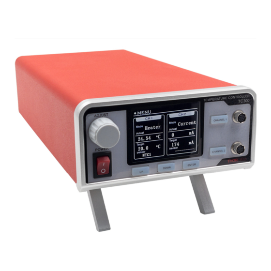
Front and Rear Panel Figure 1 TC300 Front and Rear Panel 1. LCD Screen – When the device is switched on, the main user interface is display on the LCD. 2. Adjustment Knob – The knob can be used to navigate the user interface and change values. -
Page 10: Hirose Connectors
On the front panel of the TC300, there are two 6-pin Hirose connectors. Each corresponds to an operation channel of the TC300. The two connectors allow users to wire the heaters and various type of sensors to the TC300 for temperature control operation. -
Page 11: Chapter 5 Getting Started
The TC300 is compatible with thermistors with resistance ranging up to 999 k. Most thermistors do not have a polarity. To connect a thermistor to the TC300, simply wire the thermistor to pin 4 (Sensor +) and pin 5 (Sensor -) of the Hirose connector as shown in Figure 4. -
Page 12: Platinum Resistance Temperature Sensors
Chapter 5: Getting Started 5.3.2. Platinum Resistance Temperature Sensors The TC300 is compatible with both 100 (PT100) and 1000 (PT1000) platinum resistance temperature sensors. Both 2-wire and 4-wire connections are supported. A 2-wrie platinum resistance temperature sensor usually does not have a polarity. To connect a 2-wire, simply wire the sensor to pin 4 (Sensor +) and pin 5 (Sensor -) of the Hirose connector, as shown in Figure 5. -
Page 13: Thermocouples
5.3.5. External Sensor Port The TC300 also allows the user to connect a thermistor type of temperature via the “EXT. SENSOR” port on the back panel. The EXT.SENSOR port accepts a 2.5 mm stereo earphone jack. It is directly compatible with the Thorlabs TSP-TH temperature probe sensor. -
Page 14: Turning The Tc300 On
Front Panel Operation Use the three buttons beneath the LCD to interact with the TC300. Press the “UP” and “DOWN” buttons to move the cursor on the screen. Press the “ENTER” button to confirm or cancel selection. When a value is selected, the color of the text will become yellow. -
Page 15: Menu Structure
5.6. Menu Structure The TC300 is set to single channel operation by default. When in single channel operation, only the parameters of Channel 1 will be displayed on the HOME screen and only the settings of Channel 1 will be visible in the menus. In the menus, there are three screens for setting the parameters of Channel 1 and one screen for making general optional settings of the device. -
Page 16: Compatible Thorlabs Devices
Figure 14 Menu Structure in Dual Channel Operation 5.7. Compatible Thorlabs Devices The Thorlabs devices listed are compatible with TC300. Since they are all equipped with the corresponding 6-pin Hirose connector, they support plug-and-play operation with the TC300, with no extra wiring required. -
Page 17: Chapter 6 Stand-Alone Operation
To set the operation mode of the TC300, go to the first setting screen of each channel, move the cursor on “Mode Set”, and press “ENTER” to confirm selection. Then use the knob or the “UP”/“DOWN” buttons to toggle between “Heater”... -
Page 18: Sensor Configuration
6.2.1. Thermistors (NTC1 and NTC2) When the sensor type is set to NTC1, the TC300 measures the resistance value of the thermistors wired to the Hirose connectors on front panel and calculates the temperature based on the “Beta” formulas defined below. -
Page 19: Platinum Resistance Temperature Detector (Pt100 And Pt1000)
When sensor type is set to PT100 or PT1000, the TC300 also offers the option of a user input offset to allow the device to compensate any offset in temperature measurement. -
Page 20: Thermocouple (Thermo C.)
When working with thermocouples as temperature sensors, set the sensor type to THERMO C. The TC300 supports both J type and K type thermocouples. Set the Parameter according to the actual type of the sensors that are wired to the Hirose connectors on the front panel. -
Page 21: Voltage/Current Limit
The maximum output level of voltage and current that is applied to the heater can be set on the second setting screen of each channel. TC300 will limit its output so that it will not exceed either of the max levels. These settings are valid for both heater mode and current mode. -
Page 22: Temperature Range
6.6. PID Tuning The TC300 also provides a manual tuning function on the gains of the PID control loop so that the controller can be adapted to different thermal loads. To change the value of the PID gains, go to the third setting screen of each channel. -
Page 23: Single/Dual Channel Operation
1. Make sure the heater and the sensor are both correctly connected to the TC300 and the heat load. Ensure that the TC300 is correctly configured with the correct sensor type, proper current/voltage limit and temperature range. -
Page 24: Sync Mode
6.8. Sync Mode When set to dual channel operation, the TC300 offers an extra “sync” mode on Channel 2. In sync mode, Channel 2 completely mirrors Channel 1; the two channels will be enabled and disabled together by pressing the “CHANNEL 1”... -
Page 25: Analog Output
TC300 Heater Temperature Controller Chapter 6: Stand-Alone Operation 6.10. Analog Output On the back panel, there are two analog output channels that provide analog signals that represent the temperature readings of Channel 1 and Channel 2. Analog Output of Channel 1 (ANLG1) - 0 to + 5 V output proportional to the actual temperature of Channel 1 with 0 V corresponding to the lower limit of the temperature range of Channel 1 and + 5 V corresponding to the upper limit of the temperature range of Channel 1. -
Page 26: Error Handling
An error is a state in which a critical failure occurred and all channels of the TC300 are disabled. The error and warning messages will be shown on the top right corner of the main screen. - Page 27 0 to 40 °C environment and the ventilation slots on the bottom and on the back Error HIGH HSINK The heatsink inside the TC300 is too hot panel of the device are not blocked. Contact tech support if the error continues to occur.
-
Page 28: Chapter 7 Software
Chapter 7 Software Thorlabs provides a bundled software for the TC300 which accesses all the features supported by the controller. It comes with each TC300 unit and can also be downloaded from Thorlabs website. We also provide C/C++ and LabVIEW® software development kits for controlling the TC300 with other instruments through the USB port on the controller. -
Page 29: Chapter 8 Command Line Operation
8.1. Command Line Overview The TC300 can be controlled by a command line through the USB or RS232 port, as a virtual COM device. This is to enable operation through a terminal interface or for those who wish to write their own program to control the unit. - Page 30 TC300 Heater Temperature Controller Chapter 8: Command Line Operation Command Syntax Description Get the CH1 actual temperature; returned Get CH1 Actual Temperature TACT1? value is the actual temperature in °C. Get the CH2 target temperature; returned Get CH2 Target Temperature TSET2? value is the actual temperature in °C.
- Page 31 TC300 Heater Temperature Controller Chapter 8: Command Line Operation Command Syntax Description Set the CH2 Output Current Max value, n Set CH2 Max Current CMAX2=n ranges from 10 to 2000 mA, resolution of 1 Get the CH1 Output Voltage Max value...
- Page 32 TC300 Heater Temperature Controller Chapter 8: Command Line Operation Command Syntax Description Set CH2 sensor parameter, for details see Set CH2 Sensor Parameter PARA2=n Chapter 8.3.16. Return CH1 NTC sensor β value (range: 0 Get CH1 NTC Beta Value BETA1? to 9999, resolution of 1).
- Page 33 TC300 Heater Temperature Controller Chapter 8: Command Line Operation Command Syntax Description When sensor type is set to NTC2 or EXT2, set the value of Steinhart-Hart B parameter Set CH1 Hart B Constant HARTB1=n of CH1 to n/10000, the range of n is -99999 to 99999 with a resolution of 1.
- Page 34 TC300 Heater Temperature Controller Chapter 8: Command Line Operation Command Syntax Description Set CH1 I share parameter (Gain of P) to Set CH1 I Parameter TI1=n n/100, the range of n is 0 to 999 with a resolution of 1.
-
Page 35: Description Of Commands
THORLABS TC300 is the model number, HV x.xx is hardware version, and FV x.xx device. 8.3.2. ST? – Device Status of TC300 Query device status of the TC300 device. An 8-bit binary digit will be returned. Each bit corresponds to the following definitions. Bit Number ... -
Page 36: Tset1=N; Tset1?; Tset2=N; Tset2=? - Target Temperature Of Tc300
TC300 Heater Temperature Controller Chapter 8: Command Line Operation 8.3.4. TSET1=n; TSET1?; TSET2=n; TSET2=? – Target Temperature of TC300 TSET command is used to set and query the target temperature of the TC300 device, the range is from TMIN to TMAX. TSET1=n Set target temperature of Channel 1 to n/10 °C, the setting range is defined by TMIN1 and TMAX1, setting resolution... -
Page 37: Volt1?; Volt2? - Actual Output Voltage Of Tc300
Return: 8.3.8. VOLT1?; VOLT2? – Actual Output Voltage of TC300 VOLT command is used to query the actual output voltage of the TC300 device, the range is from 0.1 to 24.0 V. VOLT1? Query actual output voltage of Channel 1, in unit of V, resolution is 0.1V VOLT2? Query actual output voltage of Channel 1, in unit of V, resolution is 0.1V... -
Page 38: Vmax1=N; Vmax1?; Vmax2=N; Vmax2? - Output Voltage Max Value Of Tc300
Return: n/1000 8.3.11. VMAX1=n; VMAX1?; VMAX2=n; VMAX2? – Output Voltage Max value of TC300 VMAX command is used to set and query the output voltage max value of the TC300 device, the range is from 0.1 to 24.0 V. VMAX1=n Set the maximum allowed voltage of Channel 1 to n/10 V, n ranges from 1 to 240, corresponding to 0.1 to 24.0 V. -
Page 39: Offset1=N; Offset1?; Offset2=N; Offset2? - Sensor Offset Value Of Tc300
8.3.15. TYPE1=n; TYPE1?; TYPE2=n; TYPE2? – Sensor Type of TC300 TYPE command is used to set and query the sensor type of the TC300 device. Channel 1 and Channel 2 share the EXT1/EXT2. Channel 2 cannnot select EXT1/EXT2 when it is configured for Channel 1 or the other way. -
Page 40: Para1=N; Para1?; Para2=N; Para2? - Sensor Parameter Of Tc300
8.3.16. PARA1=n; PARA1?; PARA2=n; PARA2? – Sensor Parameter of TC300 PARA command is used to set and query the sensor parameter of the TC300 device. 2-wire or 4-wire is only available for the PT100 or PT1000 sensor type. J type or K type is only available for Thermo Coupler sensor type. -
Page 41: Beta 1=N; Beta 1?; Beta 2=N; Beta 2? - Ntc Beta Value Of Tc300
8.3.17. BETA 1=n; BETA 1?; BETA 2=n; BETA 2? – NTC Beta Value of TC300 BETA command is used to set and query NTC beta value of the TC300 device, the range is from 0 to 9999. NTC sensor beta value is only available for NTC1 sensor type. -
Page 42: R0Ch1=N; R0Ch1?; R0Ch2=N; R0Ch2? - Thermistor R0 Value Of Tc300
8.3.20. R0CH1=n; R0CH1?; R0CH2=n; R0CH2? – Thermistor R0 value of TC300 R0CH command is used to set and query thermistor R0 value of the TC300 device, the range is from 0 to 999 k. Thermistor R0 value is only available for NTC1 or EXT1 sensor type. -
Page 43: Trig1=N ; Trig1? Trig2=N ; Trig2?- Trigger Mode Of 300
Return: 8.3.23. BRIGHT=n; BRIGHT? – Brightness of TC300 BRIGHT command is used to set and query brightness of TC300 Display, the range is from 10 to 100%. BRIGHT=n Set brightness of TC300 Display in %. The range is from 10 to 100%. Resolution is 1 %. -
Page 44: Dark=N; Dark? - Darkness Status Of Tc300
8.3.25. KB=n; KB? – Lock Status of TC300 KB command is used to set and query lock status of the TC300 knob and buttons. When lock is enabled, the TC300 will not be responding to any operation input from the knob or buttons on the front panel. -
Page 45: Td 1=N; Td 1?; Td 2=N; Td 2? - Td Value Of Pid
Set PERIOD value of PID for Channel 2, range:100 to 5000 ms, resolution: 1 ms PERIOD2? Query PERIOD value of PID for Channel 2 Return: 8.3.30. PID1DEF!; PID2DEF! – Load Default PID Parameters These commands are used to load default PID parameters of TC300. PID1DEF! Page 40 CTN017856-D02... -
Page 46: Quiet=N; Quiet? - Quiet Status Of Tc300
Copy Channel 1 parameters to Channel 2 when two channels in dual channel mode. 8.3.34. TSINK? – Heatsink Temperature of TC300 TSINK? Query the heatsink temperature of the TC300 in °C. The heatsink is the main heat dissipation element in the TC300. Return: Temperature reading on the heatsink, in unit of °C. -
Page 47: Monitor? - Monitor Messages Of Tc300
22 8.3.38. ERR? – Error Status of TC300 ERR command is used to query the error status of the TC300. A 16-bits binary digit will be returned, with each bit corresponding to the following definitions. Bit Number Error Message... -
Page 48: Warn? - Warning Status Of Tc300
Reserved Reserved 8.3.39. WARN? – Warning Status of TC300 WARN command is used to query the warning status of TC300. a 16-bits binary digit will be returned; each bit corresponds to the following definitions. Bit Number Error Message... -
Page 49: Chapter 9 Maintenance
Figure 31 Fuse Replacement 9.2. Firmware Update Thorlabs offers downloads of firmware update files for the TC300 on the website (http://www.thorlabs.com/). To update the controller firmware, connect the controller to a PC with the included USB cable. Keep holding down the “ENTER”... - Page 50 Chapter 9: Maintenance On the PC, start the firmware update tool, which can also be downloaded from the website (http://www.thorlabs.com/), select the correct COM port, and connect. Figure 33 Select COM port on Firmware Update Tool Click “Browse” to select the new firmware file.
-
Page 51: Chapter 10 Mechanical Drawing
TC300 Heater Temperature Controller Chapter 10: Mechanical Drawing Chapter 10 Mechanical Drawing Page 46 CTN017856-D02... -
Page 52: Chapter 11 Specifications
TC300 Heater Temperature Controller Chapter 11: Specifications Chapter 11 Specifications Specifications Value Max Output Power per Channel 48 W Max Output Current per Channel Max Output Voltage per Channel 24 V Temperature Setting Range Sensor dependent, -200 to 400 °C Max Set Point Resolution 0.1 °C... -
Page 53: Chapter 12 Regulatory
Waste Treatment is Your Own Responsibility If you do not return an “end of life” unit to Thorlabs, you must hand it to a company specialized in waste recovery. Do not dispose of the unit in a litter bin or at a public waste disposal site. -
Page 54: Fcc Declarations Of Conformity
TC300 Heater Temperature Controller Chapter 12: Regulatory 12.1. FCC Declarations of Conformity For Customers in the USA This equipment has been tested and found to comply with the limits for a Class A digital device, pursuant to part 15 of the FCC Rules. These limits are designed to provide reasonable protection against harmful interference when the equipment is operated in a commercial environment. -
Page 55: Ce Declarations Of Conformity
TC300 Heater Temperature Controller Chapter 12: Regulatory 12.2. CE Declarations of Conformity Page 50 CTN017856-D02... -
Page 56: Chapter 13 Thorlabs Worldwide Contacts
TC300 Heater Temperature Controller Chapter 13: Thorlabs Worldwide Contacts Chapter 13 Thorlabs Worldwide Contacts For technical support or sales inquiries, please visit us at www.thorlabs.com/contact for our most up-to-date contact information. USA, Canada, and South America UK and Ireland Thorlabs, Inc. - Page 58 www.thorlabs.com...
Need help?
Do you have a question about the TC300 and is the answer not in the manual?
Questions and answers