
Related Manuals for Carrier Fan Coil


Summary of Contents for Carrier Fan Coil
- Page 1 CARRIER CORPORATION ©2020 · Catalog No. 11-808-540-01 · 10/29/2020...
- Page 2 Important changes are listed in Document revision history at the end of this document. CARRIER CORPORATION ©2020. All rights reserved throughout the world. i-Vu is a registered trademark of Carrier Corporation. All other trademarks are the property of their respective owners.
-
Page 3: Table Of Contents
To set up the Fan Coil for N2 ......................13 Troubleshooting N2 communication ....................14 LonWorks ................................15 To set up the Fan Coil for the LonWorks Option Card (#LON-OC) ............ 15 Commissioning the controller for LonWorks communication ............16 Troubleshooting LonWorks communication ..................17 Start-up ................................... - Page 4 Contents...
-
Page 5: Introduction
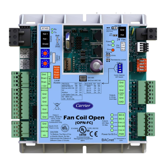
What is the Fan Coil controller? The Fan Coil controller is available as an integrated component of a Carrier packaged unit. Its internal application programming provides optimum performance and energy efficiency. Fan Coil enables the unit to run in 100% stand-alone control mode or it can communicate to the Building Automation System (BAS). -
Page 6: Safety Considerations
Introduction Safety considerations WARNING Disconnect electrical power to the Fan Coil before wiring it. Failure to follow this warning could cause electrical shock, personal injury, or damage to the controller. Fan Coil CARRIER CORPORATION ©2020 Integration Guide All rights reserved... -
Page 7: Wiring Inputs And Outputs
DX stage 1 Legend - Analog Input - Analog Output - Binary Input - Binary Output *These channels are configurable. NOTE Connect ZS or SPT sensor to the Rnet port. Fan Coil CARRIER CORPORATION ©2020 Integration Guide All rights reserved... -
Page 8: Communications Wiring
Communications wiring Communications wiring Protocol Overview You can set the Fan Coil to communicate 1 of 4 different protocols: • BACnet MS/TP (page 5) • BACnet ARC156 (page 9) • N2 (page 13) • Modbus (page 11) • LonWorks (page 15) The default setting is BACnet MS/TP. -
Page 9: Bacnet Ms/Tp
Communications wiring BACnet MS/TP To set up the Fan Coil for BACnet MS/TP The Fan Coil’s latest supported function codes and capabilities are listed on the associated Protocol Implementation Conformance Statement (PICS), Carrier BACnet PICS website http://www.bacnetinternational.net/catalog/index.php?m=28. NOTE This controller counts as a full load on the MS/TP bus. -
Page 10: Adjusting Bacnet Ms/Tp Properties Using An Equipment Touch
Max Info Frames - defines the maximum number of responses that will be sent when the Fan Coil receives the token. The default is 10 and should be ideal for the majority of applications. In cases where the Fan Coil is the target of many requests, this number could be increased as high as 100 or 200. - Page 11 On the ET System screen, click Setup. On the Setup screen, click Module Setup. On the Module Setup screen, click Communication. On the Communication screen, edit the fields as needed: Fan Coil CARRIER CORPORATION ©2020 Integration Guide All rights reserved...
-
Page 12: Troubleshooting Bacnet Ms/Tp Communication
Done. Click Save. Troubleshooting BACnet MS/TP communication For detailed troubleshooting and a list of supported objects, get the controller's BACnet PICS from the Carrier BACnet PICS website http://www.bacnetinternational.net/catalog/index.php?m=28. You must get your BACnet Object list from the manufacturer. The most common communication problems are the result of not properly following the configuration steps outlined in this manual. -
Page 13: Bacnet Arc156
EXAMPLE If the controller’s address is 25, point the arrow on the Tens (10's) switch to 2 and the arrow on the Ones (1's) switch to 5. 10's NOTE The Fan Coil recognizes its address only after power has been cycled. Set communications selector for BACnet ARC156. Set the both DIP switches 3 and 4 OFF for BACnet ARC156. -
Page 14: Troubleshooting Arc156 Communication
Attach the drain/shield wire to both ends of the network segment and through every controller ○ NOTE Use the same polarity throughout the network segment. Turn on the power for the Fan Coil by connecting power terminals. Troubleshooting ARC156 communication The most common communication problems result from not properly following the configuration steps outlined above in this manual. -
Page 15: Modbus
EXAMPLE If the controller’s address is 25, point the arrow on the Tens (10's) switch to 2 and the arrow on the Ones (1's) switch to 5. 10's NOTE The Fan Coil recognizes its address only after power has been cycled. Set communications selector for EIA-485. Set DIP switches 1 and 2 for the appropriate communications speed. See table below. -
Page 16: Troubleshooting Modbus Communication
Attach the drain/shield wire to both ends of the network segment and through every controller ○ NOTE Use the same polarity throughout the network segment. Turn on the power for the Fan Coil by connecting power terminals. Troubleshooting Modbus communication The most common communication problems result from not properly following the configuration steps outlined above in this manual. -
Page 17: Johnson N2
To set up the Fan Coil for N2 Turn off the power for the Fan Coil by disconnecting power terminals. Using the rotary switches, set a unique address. Set the Tens (10's) switch to the tens digit of the address, and set the Ones (1's) switch to the ones digit. -
Page 18: Troubleshooting N2 Communication
Refer to Appendix D for the Protocol Implementation Conformance Statement. Software settings defined through the Equipment Touch device. To confirm settings, obtain a Modstat of the device. On the Equipment Touch, click the link to the Modstat. Fan Coil CARRIER CORPORATION ©2020 Integration Guide... -
Page 19: Lonworks
Ensure that you are properly grounded. Refer to Appendix E for the LonWorks Protocol Implementation Conformance Statement (PICS). To set up the Fan Coil for the LonWorks Option Card (#LON-OC) Turn off the power for the Fan Coil by disconnecting power terminals. -
Page 20: Commissioning The Controller For Lonworks Communication
Network Management Tool. The Browse feature of the Network Management Tool allows you to read real-time values from the Fan Coil. The Network Management Tool allows you to test integration prior to binding the controller's network variables to other LonWorks nodes. -
Page 21: Troubleshooting Lonworks Communication
If the network has greater than 32 devices or exceeds 2,000 feet, a Repeater should be installed. • If a controller begins or ends a network segment, a terminating resistor may be needed. Fan Coil CARRIER CORPORATION ©2020 Integration Guide... -
Page 22: Start-Up
AC power ground could damage the USB Link and the controller. If you are not sure of the wiring polarity, use a USB isolator between the computer and the USB Link. Purchase a USB isolator online from a third-party manufacturer. Fan Coil CARRIER CORPORATION ©2020 Integration Guide... -
Page 23: Sequence Of Operation
Sequence of Operation Sequence of Operation The Fan Coil controls mechanical cooling and heating based on its own space temperature input and setpoints. An optional CO (Indoor Air Quality) sensor mounted in the space maximizes occupant comfort when used with the DCV ventilation damper option. -
Page 24: Indoor Fan
Automatic Fan Speed Control - The Fan Coil controls up to 3 fan speeds using a Fan Interface board or field- installed relays. The fan motor operates at the lowest speed possible to provide quiet and efficient fan operation with the best latent capability during cooling. -
Page 25: Cooling
Cooling The Fan Coil operates one stage of DX cooling or chilled water valve (2-position or modulating) to maintain the desired cooling setpoint. The PI (Proportional-integral) cooling algorithm controls the cooling. The desired Supply Air Temperature setpoint [Cooling Control Setpoint] is calculated by the controller. -
Page 26: Heating
5 minutes. Heating The Fan Coil operates one stage of electric heat or a hot water valve (2-position or modulating) to maintain the desired heating setpoint. The heating is controlled by the PI (Proportional-integral) heating algorithm. The desired Supply Air Temperature setpoint [Heating Control Setpoint] is calculated by the Fan Coil. This setpoint is compared to the actual supply air temperature and used to determine valve operation for modulating or 2-position control valves or staging for electric heat. -
Page 27: Changeover Mode Detection
SAT at the configured Fan Off Value temperature. Changeover mode detection The Fan Coil control determines the changeover mode for 2-pipe heating/cooling systems. The controller monitors a local changeover thermistor sensor or switch, dependent upon configuration. User-configurable temperature setpoints determine the heat or cool mode. -
Page 28: Indoor Air Quality
Sequence of Operation Indoor air quality The Fan Coil controls either 2-position or Demand Controlled Ventilation (DCV) to provide the necessary ventilation to the occupied space. To meet any ventilation requirement, the fan must always be configured for the Continuous or Always On mode of operation. If the fan is configured for Automatic operation, the fan is started during occupied periods, if required, but ASHRAE base ventilation requirements will NOT be met using Automatic fan operation. -
Page 29: Dehumidification
Demand Limiting The Fan Coil accepts 3 levels of demand limit from the network. In response to a demand limit, the unit decreases its heating setpoint and increases its cooling setpoint to widen the range in order to immediately lower the electrical demand. -
Page 30: Thermostat Linkage
The fan coil uses this information to provide the air required to satisfy the load in the zones. The operating mode and supply air temperature of the fan coil is sent to all the zones in the system. Airside Linkage has the highest priority and overrides both local control and Thermostat Linkage. -
Page 31: Compliance
BACnet Compliance Compliance of listed products to requirements of ASHRAE Standard 135 is the responsibility of BACnet International. BTL ® is a registered trademark of BACnet International. Fan Coil CARRIER CORPORATION ©2020 Integration Guide All rights reserved... -
Page 32: Appendix A: Fan Coil Network Points List
Appendix A: Fan Coil Network Points List Appendix A: Fan Coil Network Points List Third party access to BACnet points in a controller BACnet system points in the i-Vu® Open controllers match physical I/O points to data, such as Outside Air Temp, to be written to the controller through the network, rather than by using a local hardwired sensor. - Page 33 Appendix A: Fan Coil Network Points List BACnet System Valid Range BACnet/ LonWorks Recommended Write Points Display Modbus Default Value* Rrefresh Name /N2 Default Value* Time (min/max) through BACnet) 3 = BAS On/Off (third party control)* 4 = Remote Occ Input...
-
Page 34: Network Points List For Bacnet And Modbus
Appendix A: Fan Coil Network Points List Commanded Points Control Points Type / Type / Display Name Object Name Display Name Object Name Instance Instance †System bv:1906 press_override Pressurization bv:7038 press_alarm Pressurization BAS On/Off msv:1001 keypad_ovrde Occupancy Status bv:2008 occ_status [Occupancy] †... - Page 35 Appendix A: Fan Coil Network Points List BACnet Modbus Point Name Point Units Default BACnet Point Name BACnet Modbus Register Modbus Access Value Object ID Type Register # Space Relative space_rh AV:1011 Input Register Humidity (Float) Space °F space_temp AV:2007...
- Page 36 Appendix A: Fan Coil Network Points List BACnet Modbus Point Name Point Units Default BACnet Point Name BACnet Modbus Register Modbus Access Value Object ID Type Register # (1) Alarm Fan / Speed (1) Off fan_run MSV:2004 Input Register (2) Low...
- Page 37 Appendix A: Fan Coil Network Points List BACnet Modbus Point Name Point Units Default BACnet Point Name BACnet Modbus Register Modbus Access Value Object ID Type Register # (5) Freecool (6) Pressure (7) Evac (8) Vent Space Temp (1) Sensor...
-
Page 38: Network Points List For N2 And Lonworks
Appendix A: Fan Coil Network Points List Network points list for N2 and LonWorks LonWorks Point Name Point Units Default SNVT Type SNVT Name Access Value Network Network Point Point Type Address Cooling Lockout °F SNVT_temp_p(105) nviClLckTemp Temperature Cooling Output... - Page 39 Appendix A: Fan Coil Network Points List LonWorks Point Name Point Units Default SNVT Type SNVT Name Access Value Network Network Point Point Type Address Enable Dehumidification Inactive SNVT_switch(95) nvoDehmRelay Active Filter (0) Normal SNVT_switch(95) nvoFilter (1) Alarm Fire / Smoke...
- Page 40 Appendix A: Fan Coil Network Points List LonWorks Point Name Point Units Default SNVT Type SNVT Name Access Value Network Network Point Point Type Address System Mode (1) Off SNVT_count_inc(9) nvoOpMode (2) Fan Only (3) Economize (4) Cooling (5) Heating...
- Page 41 Appendix A: Fan Coil Network Points List LonWorks Point Name Point Units Default SNVT Type SNVT Name Access Value Network Network Point Point Type Address Supply Fan Status (0) Off SNVT_switch(95) nvoFanStatus (1) On ZS Sensor (0) Normal SNVT_switch(95) nvoZsCfgFl...
-
Page 42: Appendix B: Bacnet Protocol Implementation Conformance Statement
Appendix B: BACnet Protocol Implementation Conformance Statement Appendix B: BACnet Protocol Implementation Conformance Statement The PIC statements are updated regularly. Please refer to the BACnet website http://www.bacnetinternational.net/catalog/index.php?m=28 for the latest information. Fan Coil CARRIER CORPORATION ©2020 Integration Guide All rights reserved... -
Page 43: Bacnet Data Link Layer Options
XX ISO 10646 (ICS-4) XX JIS C 6226 If this product is a communication gateway, describe the types of non-BACnet equipment/networks what the gateway supports: Various protocols, depending on which firmware is loaded. Fan Coil CARRIER CORPORATION ©2020 Integration Guide All rights reserved... -
Page 44: Appendix C: Johnson Controls N2 Protocol Implementation Conformance Statement
Read Analog Input Write Internal Parameter Read Binary Input Override Analog Input Read Analog Output Override Binary Input Read Binary Output Override Internal Parameter Read Internal Parameter Override Release Request Fan Coil CARRIER CORPORATION ©2020 Integration Guide All rights reserved... -
Page 45: Appendix D: Modbus Protocol Implementation Conformance Statement
0 = Off, 1 = On 2 – Read Input Status 1 – Read Coil Status Discrete Output (DO) 0 = Off, 1 = On 5 – Force Single Coil 15 – Force Multiple Coils Fan Coil CARRIER CORPORATION ©2020 Integration Guide All rights reserved... -
Page 46: Appendix E: Lonworks Protocol Implementation Conformance Statement
LonWorks network points are spawned within the device as a result of downloading graphical control programs. The Fan Coil controller speaks the LonWorks Protocol as described by Echelon Protocol Specification. Since the controller is custom-programmable it does not conform to LonMark certification. Further details on the LonWorks supported implementation are described below. - Page 47 SNVT_defr_term SNVT_lev_cont SNVT_res_kilo SNVT_volt_kilo SNVT_density SNVT_lev_cont_f SNVT_rpm SNVT_volt_mil SNVT_density_f SNVT_lev_disc SNVT_scene SNVT_vol_f SNVT_dev_c_mode SNVT_lev_percent SNVT_scene_cfg SNVT_vol_kilo SNVT_earth_pos SNVT_lux SNVT_setting SNVT_vol_mil SNVT_elapsed_tm SNVT_magcard SNVT_smo_obscur SNVT_zerospan SNVT_elec_kwh SNVT_mass SNVT_sound_db SNVT_elec_kwh_1 SNVT_mass_f SNVT_sound_db_f Fan Coil CARRIER CORPORATION ©2020 Integration Guide All rights reserved...
-
Page 48: Document Revision History
Code* 10/29/20 Sequence of Operation > Indoor fan Corrected the default from Continuous to Auto. C-TS-BL-E 8/18/20 Cover, What is the Fan Coil Updated company logo 11/19/19 Appendix A: Network Points List > New Topic C-TS-JN-E-RD Third party access to BACnet points in... - Page 50 CARRIER CORPORATION ©2020 · Catalog No. 11-808-540-01 · 10/29/2020...
Need help?
Do you have a question about the Fan Coil and is the answer not in the manual?
Questions and answers