
Related Manuals for SCHUNK OPR 048


Summary of Contents for SCHUNK OPR 048
- Page 1 Original operating manual Assembly and Operating Manual OPR 048 Collision and Overload Protection Sensor...
- Page 2 Imprint Copyright: This manual is protected by copyright. The author is SCHUNK GmbH & Co. KG. All rights re- served. Any reproduction, processing, distribution (making available to third parties), translation or other usage - even excerpts - of the manual is especially prohibited and re- quires our written approval.
-
Page 3: Table Of Contents
6.3.3 Determining Exact Pressure Required ............ 27 Operation ....................... 28 Troubleshooting ..................... 29 Maintenance ...................... 30 General ....................... 30 Cable Replacement..................... 31 Replacement of connector block assembly............ 31 Periodic Lubrication Instructions................ 32 02.00 | OPR 048 | Assembly and Operating Manual | en | 389630... - Page 4 10 Assembly drawings .................... 36 10.1 Assembly Drawing .................... 37 10.2 Replacement Parts ..................... 38 11 Translation of original declaration of incorporation .......... 39 12 Annex to Declaration of Incorporation .............. 40 02.00 | OPR 048 | Assembly and Operating Manual | en | 389630...
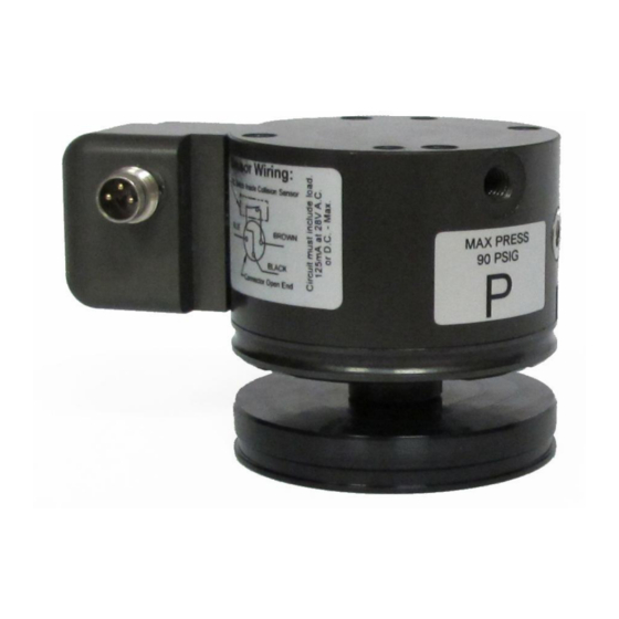
- Page 5 Cover Plate Disk-shaped aluminum cover for OPR Body. M8, 3-Pin Male Threaded Connector 8mm electrical connector mounted in a block attached to the side of the Body. 02.00 | OPR 048 | Assembly and Operating Manual | en | 389630...
-
Page 6: About This Manual
Dangers for persons! Non-observance can lead to irreversible injury and even death. CAUTION Dangers for persons! Non-observance can cause minor injuries. NOTICE Material damage! Information about avoiding material damage. 02.00 | OPR 048 | Assembly and Operating Manual | en | 389630... -
Page 7: Applicable Documents
• General terms of business* • Catalog data sheet of the purchased product * The documents marked with an asterisk (*) can be downloaded on our homepage schunk.com 02.00 | OPR 048 | Assembly and Operating Manual | en | 389630... -
Page 8: Basic Safety Notes
Incorrect ambient and operating conditions can make the product unsafe, leading to the risk of serious injuries, considerable material damage and/or a significant reduction to the product's life span. 02.00 | OPR 048 | Assembly and Operating Manual | en | 389630... -
Page 9: Personnel Qualification
• When working on and with the product, observe the occupa- tional health and safety regulations and wear the required per- sonal protective equipment. • Observe the valid safety and accident prevention regulations. 02.00 | OPR 048 | Assembly and Operating Manual | en | 389630... - Page 10 • Wear protective gloves and safety goggles when handling haz- ardous substances. • Wear close-fitting protective clothing and also wear long hair in a hairnet when dealing with moving components. 02.00 | OPR 048 | Assembly and Operating Manual | en | 389630...
-
Page 11: Notes On Safe Operation
• Eliminate any malfunction immediately. • Observe the care and maintenance instructions. • Observe the current safety, accident prevention and environ- mental protection regulations regarding the product's applica- tion field. 02.00 | OPR 048 | Assembly and Operating Manual | en | 389630... -
Page 12: Transport
The incorrect handling of disposal may impair the product's safety and cause serious injuries as well as considerable material and en- vironmental harm. • Follow local regulations on dispatching product components for recycling or proper disposal. 02.00 | OPR 048 | Assembly and Operating Manual | en | 389630... -
Page 13: Notes On Particular Risks
Risk of injury from overload signal of the sensor (eg electrical short circuit) and in case of failure and reducing the supply of compressed air! The function of the electrical signal transmis- sion is no longer guaranteed. 02.00 | OPR 048 | Assembly and Operating Manual | en | 389630... -
Page 14: Warranty
• Observe the specified maintenance and lubrication intervals • Observe the ambient conditions and operating conditions Parts touching the workpiece and wear parts are not included in the warranty. 02.00 | OPR 048 | Assembly and Operating Manual | en | 389630... -
Page 15: Technical Data
3-pole Nano Con- nector Optional interated springs available corresponding to 0.3, 0.7, 1 bar More technical data is included in the catalog data sheet. Whichever is the latest version. 02.00 | OPR 048 | Assembly and Operating Manual | en | 389630... -
Page 16: Product Overview
(travel) provided by the OPR before the switch circuit opens is adjustable by turning a switch adjustment screw. All OPR devices provide axial (compression only), torsional, and moment compliance. 02.00 | OPR 048 | Assembly and Operating Manual | en | 389630... -
Page 17: Description
OPR body. The size and location of these connections are shown in the drawing provided at the end of this manual. 02.00 | OPR 048 | Assembly and Operating Manual | en | 389630... -
Page 18: Assembly
Do not supply air pressure at this time. All mounting hardware should be tightened. The use of an indus- trial thread-locking compound is recommended for all fasteners. 02.00 | OPR 048 | Assembly and Operating Manual | en | 389630... - Page 19 OPR-131 M6 - 69 mm 9.0 - 11.9 Nm OPR-176 M8 - 80 mm 21.5 - 28.2 Nm OPR-221 M10 - 100 mm 44.0 - 58.8 Nm 02.00 | OPR 048 | Assembly and Operating Manual | en | 389630...
-
Page 20: Electrical Connection
SCHUNK Mechanical connection 18], utilize the brown-black-blue color code indicated. Break switch in the OPR Brown Blue Black Switch wiring as a normaly-closed , dry contact switch 02.00 | OPR 048 | Assembly and Operating Manual | en | 389630... - Page 21 Switch wiring as a normaly-open PNP or NPN proximity switch OPR-081-221 NC Switch Inside OPR Brown Blue Black Switch wiring as a normaly-closed , dry contact switch 02.00 | OPR 048 | Assembly and Operating Manual | en | 389630...
- Page 22 When the collision occurs the switch will open and the test ✓ light will turn off Release the OPR and it will return to its working position. Ø The test light will illuminate ✓ 02.00 | OPR 048 | Assembly and Operating Manual | en | 389630...
-
Page 23: Switch Adjustment
If the distance traveled is greater than desired turn the adjust- Ø ment screw counterclockwise. If the distance traveled is less turn the proximity switch clockwise. 02.00 | OPR 048 | Assembly and Operating Manual | en | 389630... -
Page 24: Pneumatic
Paint of Face Center of Direction of Robot Gravity Application Motion Relevant to Dynamic Component (F1, F2, F3 Resolved Principal Forces) of F1 Collision Sensor Loading Diagram 02.00 | OPR 048 | Assembly and Operating Manual | en | 389630... - Page 25 Forces are generated at the tool-tip under normal working con- ditions. If these forces and their location are known, they can be converted into loads on the OPR using the same technique. 02.00 | OPR 048 | Assembly and Operating Manual | en | 389630...
-
Page 26: Obtain Required Pressure Setting
• If the unit is equipped with P05 (0,33 bar equivalent), P10 (0,66 bar equivalent), or P15 (1 bar equivalent) preload spring, sub- tract this pressure to determine the actual pressure to be sup- plied. 02.00 | OPR 048 | Assembly and Operating Manual | en | 389630... -
Page 27: Determining Exact Pressure Required
Use of pressures in excess of 6,2 Bar can result in excessive damage to the unit in the event of a crash and voids the war- ranty. 02.00 | OPR 048 | Assembly and Operating Manual | en | 389630... -
Page 28: Operation
Using these techniques, the OPR may be supplied with higher air pressure when higher loads or accelera- tions are anticipated. 02.00 | OPR 048 | Assembly and Operating Manual | en | 389630... -
Page 29: Troubleshooting
If the OPR still fails to reset or if the switch fails to close after ad- justment when the unloaded unit is in its working condition, con- tact SCHUNK. 02.00 | OPR 048 | Assembly and Operating Manual | en | 389630... -
Page 30: Maintenance
Such maintenance work should be conducted every 5.000 or fewer collisions. • Check the control wiring for shorts. • If necessary, readjust the switiching point. 02.00 | OPR 048 | Assembly and Operating Manual | en | 389630... -
Page 31: Cable Replacement
Insert the new socket head cap screws, and tighten to 1,4 Nm. Ø Adjust per Switch Adjustment 23]. Ø 02.00 | OPR 048 | Assembly and Operating Manual | en | 389630... -
Page 32: Periodic Lubrication Instructions
Do not allow either of these assem- blies to be mixed with those from other units. Clean the lubricant from the top surface of the Piston. Ø 02.00 | OPR 048 | Assembly and Operating Manual | en | 389630... - Page 33 Remove the Stem assembly and clean the lubricant from the Ø working surfaces of the balls and the Stem. Set the Stem as- sembly aside for later re-use. 02.00 | OPR 048 | Assembly and Operating Manual | en | 389630...
-
Page 34: Cover And Stem Re-Assembly
Ø Apply liquid screw lock (low-strength) to the four socket flat Ø head cap screws and thread them into the Body. Tighten the screws to 2.8 Nm 02.00 | OPR 048 | Assembly and Operating Manual | en | 389630... -
Page 35: Weld Splatter Shield Replacement
Apply liquid screw lock (low-strength) to threads of the three Ø M2.5 x 6mm ISO 10642 and install through the Shield Retainer into the Cover Plate. Tighten to 0,4 Nm. 02.00 | OPR 048 | Assembly and Operating Manual | en | 389630... -
Page 36: Assembly Drawings
10 Assembly drawings The following figures are example images. They serve for illustra- tion and assignment of the spare parts. Variations are possible de- pending on size and variant. 02.00 | OPR 048 | Assembly and Operating Manual | en | 389630... -
Page 37: Assembly Drawing
Assembly drawings 10.1 Assembly Drawing 02.00 | OPR 048 | Assembly and Operating Manual | en | 389630... -
Page 38: Replacement Parts
Assembly drawings 10.2 Replacement Parts 02.00 | OPR 048 | Assembly and Operating Manual | en | 389630... -
Page 39: Translation Of Original Declaration Of Incorporation
Person authorized to compile the technical documentation: Robert Leuthner, Address: see manufacturer's address Lauffen/Neckar, January 2019 p.p. Ralf Winkler, Manager for development of grip- ping system components 02.00 | OPR 048 | Assembly and Operating Manual | en | 389630... -
Page 40: Annex To Declaration Of Incorporation
Risk of break-up during operation 1.3.3 Risks due to falling or ejected objects 1.3.4 Risks due to surfaces, edges or angles 1.3.5 Risks related to combined machinery 02.00 | OPR 048 | Assembly and Operating Manual | en | 389630... - Page 41 1.5.16 Lightning Maintenance 1.6.1 Machinery maintenance 1.6.2 Access to operating positions and servicing points 1.6.3 Isolation of energy sources 1.6.4 Operator intervention 1.6.5 Cleaning of internal parts 02.00 | OPR 048 | Assembly and Operating Manual | en | 389630...
- Page 42 Supplementary essential health and safety requirements for machinery intended for underground work Supplementary essential health and safety requirements for machinery presenting particular hazards due to the lifting of persons 02.00 | OPR 048 | Assembly and Operating Manual | en | 389630...
- Page 43 Notes Notes 02.00 | OPR 048 | Assembly and Operating Manual | en | 389630...
- Page 44 02.00 | OPR 048 | Assembly and Operating Manual | en | 389630...
Need help?
Do you have a question about the OPR 048 and is the answer not in the manual?
Questions and answers