
Related Manuals for SCHUNK FT-AXIA Series


Summary of Contents for SCHUNK FT-AXIA Series
- Page 1 Translation of Original Operating Manual Assembly and Operating Manual FT-AXIA Force/torque sensor...
- Page 2 Imprint Imprint Copyright: This manual is protected by copyright. The author is SCHUNK GmbH & Co. KG. All rights reserved. Technical changes: We reserve the right to make alterations for the purpose of technical improvement. Document number: 1517831 Version: 02.00 | 21/11/2022 | en...
-
Page 3: Table Of Contents
Table of Contents Table of Contents General........................ 5 About this manual .................... 5 1.1.1 Presentation of Warning Labels ............... 5 1.1.2 Applicable documents ................ 5 1.1.3 Variants..................... 6 1.1.4 Sizes ...................... 6 1.1.5 Calibration variants................... 6 Warranty ...................... 7 Scope of delivery .................... 7 Accessories ...................... 7 Basic safety notes .................... - Page 4 Table of Contents Maintenance ...................... 36 Maintenance intervals.................. 36 Checking the measured data ................ 36 Removing the product from the robot arm............ 37 EU Declaration of Conformity ................. 38 UKCA Declaration of Conformity ................ 39 10 Appendix to the declaration of conformity ............. 40 02.00 | FT-AXIA | Assembly and Operating Manual | en | 1517831...
-
Page 5: General
• Catalog data sheet of the purchased product * • Commissioning instructions for the force-torque-sensor system The documents labeled with an asterisk (*) can be downloaded from schunk.com. 02.00 | FT-AXIA | Assembly and Operating Manual | en | 1517831... -
Page 6: Variants
General 1.1.3 Variants This operating manual applies to the following variations: • Force/torque sensor FT-AXIA with FTN-interface • Force/torque sensor FT-AXIA with FTE-interface • Force/torque sensor FT-AXIA with FTRS-interface 1.1.4 Sizes This operating manual applies to the following sizes: • FT-AXIA80 • FT-AXIA90 •... -
Page 7: Warranty
General 1.2 Warranty If the product is used as intended, the warranty is valid for 12 months from the ex-works delivery date under the following conditions: • Observe the ambient conditions and operating } 2.5 [ / 9] conditions, } 7 [ / 36] •... -
Page 8: Basic Safety Notes
Use of unauthorized spare parts Using unauthorized spare parts can endanger personnel and damage the product or cause it to malfunction. • Use only original spare parts or spares authorized by SCHUNK. 02.00 | FT-AXIA | Assembly and Operating Manual | en | 1517831... -
Page 9: Ambient Conditions And Operating Conditions
Basic safety notes 2.5 Ambient conditions and operating conditions Required ambient conditions and operating conditions Incorrect ambient and operating conditions can make the product unsafe, leading to the risk of serious injuries, considerable material damage and/or a significant reduction to the product's life span. •... -
Page 10: Personal Protective Equipment
Basic safety notes 2.7 Personal protective equipment Use of personal protective equipment Personal protective equipment serves to protect staff against danger which may interfere with their health or safety at work. • When working on and with the product, observe the occupational health and safety regulations and wear the required personal protective equipment. -
Page 11: Disposal
Basic safety notes 2.10 Disposal Handling of disposal The incorrect handling of disposal may impair the product's safety and cause serious injuries as well as considerable material and environmental harm. • Follow local regulations on dispatching product components for recycling or proper disposal. 2.11 Fundamental dangers General •... -
Page 12: Protection During Commissioning And Operation
Basic safety notes 2.11.2 Protection during commissioning and operation Falling or violently ejected components Falling and violently ejected components can cause serious injuries and even death. • Take appropriate protective measures to secure the danger zone. • Never step into the danger zone during operation. NOTICE Material damage due to incorrect grounding! Damage to the sensor due to electrostatic discharge possible. -
Page 13: Technical Data
Technical data 3 Technical data 3.1 Basic data Designation FT-AXIA80 -DUAL -DUAL -DUAL SI-75-4/ SI-200-8/ SI-480-20/ SI-150-8 SI-500-20 SI-1200-50 Weight [kg] 0.28 0.68 Material Aluminum Stainless steel Height [mm] 25.4 Diameter [mm] Supply voltage [VDC] 12-30 Max. Power consumption [W] Stiffness (calculated) X-axis &... - Page 14 Technical data Designation FT-AXIA90-SI-1000-50 Weight [kg] 0.74 Material Aluminum Height [mm] 26.9 Diameter [mm] 89.9 Supply voltage [VDC] 12-30 Max. Power consumption [W] Stiffness (calculated) X-axis & Y-axis forces (Kx, Ky) [N/m] 6.3 x 10 Z-axis forces (Kz) [N/m] 1.4 x 10 X-axis & Y-axis torques (Ktx, Kty) 9.6 x 10 [Nm/rad] Z-axis torques (Ktz) [Nm/rad]...
- Page 15 Technical data Designation FT-AXIA130 -SI-2000-125 -SI-4000-300 Weight [kg] 0.86 1.88 Material Aluminum Stainless steel Height [mm] 39.2 Diameter [mm] Supply voltage [VDC] 12-30 Max. Power consumption [W] Stiffness (calculated) X-axis & Y-axis forces (Kx, Ky) [N/m] 5.8 x 10 1.5 x 10 Z-axis forces (Kz) [N/m] 8.6 x 10 2.2 x 10 X-axis &...
-
Page 16: Ambient Conditions And Operating Conditions
Technical data 3.2 Ambient conditions and operating conditions Designation FT-AXIA Storage temperature [°C] Min. Max. Operating temperature [°C] Min. Max. Relative air humidity [%] <95, non-condensing IP rating The catalog data sheet contains more information. 3.3 Standard peak values NOTE When switched on, the sensor records the peak values loaded on each individual axis. -
Page 17: Maximum Permissible Load
Technical data Designation Fxy [N] Fz [N] Mxy [Nm] FT-AXIA130-SI-2000-125 Positive default 2.25 x 10 7.05 x 10 1.2 x 10 value Negative -2.25 x 10 -7.05 x 10 -1.2 x 10 default value FT-AXIA130-SI-4000-300 Positive default 8.4 x 10 1.26 x 10 6.3 x 10 value Negative -8.4 x 10 -1.26 x 10 -6.3 x 10 default value 3.4 Maximum permissible load The force/torque sensors have 3 different indicators that a sensor is being used outside of its calibrated range: •... - Page 18 Technical data FT-AXIA80 Calibration [Nmm] x/y/z SI-150-8 FT-AXIA80-DUAL SI-150-8 FT outside the range Measuring device outside the range Sensor mode not guaranteed FT-AXIA80-DUAL SI-150-8 FT outside the range Measuring device outside the range Sensor mode not guaranteed 02.00 | FT-AXIA | Assembly and Operating Manual | en | 1517831...
- Page 19 Technical data FT-AXIA80 Calibration [Nmm] x/y/z SI-500-20 FT-AXIA80-DUAL SI-500-20 FT outside the range Measuring device outside the range Sensor mode not guaranteed FT-AXIA80-DUAL SI-500-20 FT outside the range Measuring device outside the range Sensor mode not guaranteed 02.00 | FT-AXIA | Assembly and Operating Manual | en | 1517831...
- Page 20 Technical data FT-AXIA80 Calibration [Nmm] x/y/z SI-1200-50 1,200 2,000 FT-AXIA80-DUAL SI-1200-50 FT outside the range Measuring device outside the range Sensor mode not guaranteed FT-AXIA80-DUAL SI-1200-50 FT outside the range Measuring device outside the range Sensor mode not guaranteed 02.00 | FT-AXIA | Assembly and Operating Manual | en | 1517831...
- Page 21 Technical data FT-AXIA90 Calibration [Nmm] x/y/z SI-1000-50 1,000 2,000 FT-AXIA90-DUAL SI-1000-50 FT outside the range Measuring device outside the range Sensor mode not guaranteed FT-AXIA90-DUAL SI-1000-50 FT outside the range Measuring device outside the range Sensor mode not guaranteed 02.00 | FT-AXIA | Assembly and Operating Manual | en | 1517831...
- Page 22 Technical data FT-AXIA130 Calibration [Nmm] x/y/z SI-2000-125 2,000 4,000 FT-AXIA130-DUAL SI-2000-125 FT outside the range Measuring device outside the range Sensor mode not guaranteed FT-AXIA130-DUAL SI-2000-125 FT outside the range Measuring device outside the range Sensor mode not guaranteed 02.00 | FT-AXIA | Assembly and Operating Manual | en | 1517831...
- Page 23 Technical data FT-AXIA130 Calibration [Nmm] x/y/z SI-4000-300 4,000 6,000 FT-AXIA130-DUAL SI-4000-300 FT outside the range Measuring device outside the range Sensor mode not guaranteed FT-AXIA130-DUAL SI-4000-300 FT outside the range Measuring device outside the range Sensor mode not guaranteed 02.00 | FT-AXIA | Assembly and Operating Manual | en | 1517831...
-
Page 24: Design And Description
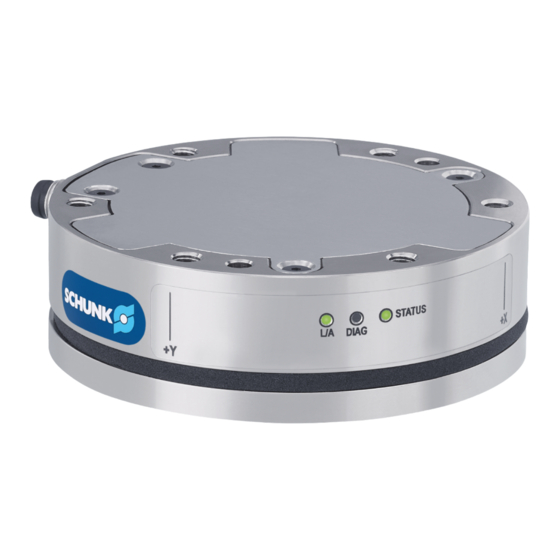
Design and description 4 Design and description 4.1 Design FT-AXIA80 Plug connection with fitting for power and signal cable, 6- pin, M8 Robot side (for adapter plate or robot) Tool side (for customer tool or end effector) Communication and status LEDs Seal for protection class IP64 FT-AXIA90 Plug connection with fitting for power and signal cable, 8-... -
Page 25: Description
Design and description FT-AXIA130 Plug connection with fitting for power and signal cable, 8- pin, M12 Robot side (for adapter plate or robot) Tool side (for customer tool or end effector) Communication and status LEDs Identification groove Through-hole with 50 mm diameter Terminal block with adjustable alignment 4.2 Description Rigid 6-axis force-torque-sensor for precise measuring in all six... -
Page 26: Assembly
Assembly 5 Assembly 5.1 Assembly and connection WARNING Risk of injury due to unexpected movements! If the power supply is switched on or residual energy remains in the system, components can move unexpectedly and cause serious injuries. Before starting any work on the product: Switch off the power •... -
Page 27: Adjusting The Alignment Of The Terminal Block
Assembly 5.2 Adjusting the alignment of the terminal block WARNING Risk of damage to the sensor! Only align the terminal block when the sensor is switched off and completely dry. Terminal block FT-AXIA130 NOTE The standard alignment of the terminal block is position 1. 1. - Page 28 Assembly Adapter plate Adapter plates can be inserted between the robot and the force- requirements torque-sensor or between the force-torque-sensor and the tool. An adapter plate is necessary if the screw connection diagram of the force-torque-sensor has to be adapted to the customer's equipment (robot flange, end effector).
- Page 29 Assembly • To guarantee the necessary tightening torque, the adapter plate must have a sufficient height. • The mounting screws must not be too long in order to prevent damage to the internal electronics of the force-torque-sensor. The adapter plate must have an even and stable surface running parallel to the force-torque-sensor to prevent distortion during operation.
- Page 30 Assembly FT-AXIA80 1. Clean the mounting surfaces. 2. Mount the adapter plate (4) on the robot (1) with mounting screws (5) and cylindrical pin (3).IMPORTANT! The screws must have a minimum screw-in length of 4.5 mm. IMPORTANT! Apply Loctite 242 threadlocker to the mounting screws (2). 3. Fasten the force/torque sensor (7) to the adapter plate (4) with mounting screws (2) and cylindrical pin (6).
- Page 31 Assembly FT-AXIA90 1. Clean the mounting surfaces. 2. Mount the adapter plate (3) on the robot (1) with mounting screws (5) and cylindrical pin (2).IMPORTANT! The screws must have a minimum screw-in length of 4.5 mm. IMPORTANT! Apply Loctite 242 threadlocker to the mounting screws (2). 3. Fasten the force/torque sensor (7) to the adapter plate (3) with mounting screws (8) and cylindrical pins (4).
- Page 32 Assembly FT-AXIA130 1. Clean the mounting surfaces. 2. Mount the adapter plate (3) on the robot (1) with mounting screws (4) and cylindrical pin (2). IMPORTANT! The screws must have a minimum screw-in length of 8 mm. IMPORTANT! Apply Loctite 242 threadlocker to the mounting screws (2). 3. Fasten the force/torque sensor (6) to the adapter plate (3) with mounting screws (7) and cylindrical pin (5).
-
Page 33: Electrical Connection
Assembly 5.3.2 Electrical connection NOTICE Risk of damage to the sensor cable! The sensor cable can get damaged in moving applications. Observe the bending radius of the cable. • Secure the cable close to the connector. • Leave enough clearance to allow the robot to move. •... -
Page 34: Start-Up
Start-up 6 Start-up 6.1 Tool conversion The tool conversion enables forces and torques to be measured at a reference point other than the sensor's point of origin. NOTICE Overload during tool conversion The forces and torques applied to the travel paths need to be observed to prevent the product getting damaged. - Page 35 Start-up Tool conversion example sketch With this example, the rotation about the Z-axis results only from the rotations about the X and Y-axis; the tool does not turn about the Z-axis itself in this application. 02.00 | FT-AXIA | Assembly and Operating Manual | en | 1517831...
-
Page 36: Maintenance
Disassembly or opening of the product is not permitted. • Only allow SCHUNK to repair the product. • This product must not be disassembled for maintenance. Have all repair work on the product carried out only by SCHUNK. 7.1 Maintenance intervals Maintenance interval Maintenance work weekly... -
Page 37: Removing The Product From The Robot Arm
Maintenance 7.3 Removing the product from the robot arm WARNING Risk of injury due to sudden movements! If the energy supply is switched on or if residual energy is still present in the system, this can cause components to move unexpectedly, which may result in serious injuries and material damage. -
Page 38: Eu Declaration Of Conformity
Directive 2014/30/EU and will be made available to national authorities on demand. The signatory is resident at the manufacturer's address and is authorized to compile this documentation. Signed for and on behalf of: SCHUNK GmbH & Co. KG Lauffen/Neckar, November 2022 Dr.-Ing. Manuel Baumeister, Technology &... -
Page 39: Ukca Declaration Of Conformity
Safety of machinery - General principles for design - Risk assessment and risk reduction Person authorized to compile the technical documentation: Marcel Machado, address: refer to manufacturer's address Signed for and on behalf of: SCHUNK GmbH & Co. KG Lauffen/Neckar, November 2022 Dr.-Ing. Manuel Baumeister, Technology & Innovation... -
Page 40: Appendix To The Declaration Of Conformity
Appendix to the declaration of conformity 10 Appendix to the declaration of conformity This declaration of conformity is valid for all variants of the force/ torque sensor mentioned in this appendix. FTN-interface FTN-AXIA80-DUAL SI-75-4/SI-150-8 FTN-AXIA80-DUAL SI-200-8/SI-500-20 FTN-AXIA80-UR-DUAL SI-200-8/SI-500-20 FTN-AXIA80-DUAL SI-480-20/SI-1200-50 FTN-AXIA90-SI-1000-50 FTN-AXIA130-SI-2000-125 FTN-AXIA130-SI-4000-300... - Page 44 Translation of Original Operating Manual SCHUNK GmbH & Co. KG Clamping and gripping technology Bahnhofstr. 106 - 134 D-74348 Lauffen/Neckar Tel. +49-7133-103-0 Fax +49-7133-103-2399 info@de.schunk.com schunk.com Folgen Sie uns I Follow us...
Need help?
Do you have a question about the FT-AXIA Series and is the answer not in the manual?
Questions and answers