
Related Manuals for HYDAC FILTER SYSTEMS FluidControl FCU 8111


Summary of Contents for HYDAC FILTER SYSTEMS FluidControl FCU 8111
- Page 1 FCU 8111 /-Aviation FluidControl Unit Operating and Maintenance Instructions Valid from firmware versions 3.32 up English (translation of original instructions) Keep for future reference. Document No.: 3690427a...
-
Page 2: Imprint
+49 6897 509 1394 E-Mail: guenter.harge@hydac.com © HYDAC FILTER SYSTEMS GMBH All rights reserved. No part of this work may be reproduced in any form (print, photocopy or by other means) or processed, duplicated or distributed using electronic systems without the written consent of the publisher. -
Page 3: Table Of Contents
Content Content Imprint ......................2 Documentation Representative ..............2 Content ......................3 Preface ......................7 Technical Support ..................7 Modifications to the Product ................ 7 Warranty ...................... 7 Using the documentation ................8 Safety information ..................9 Hazard symbols ................... 9 Signal words and their meaning in the safety information and instructions .................... - Page 4 Content Contact assignment (switched position when the FCU is ready for operation) ..................28 Relay Functions ..................29 Adjustable limit values ................32 FCU in online operation ................33 Switching on the FCU ................35 Conducting Measurements via the High-Pressure Port (INLET) ....35 Operating the FCU ..................
- Page 5 Content MODE M3 ....................62 MODE M4 ....................63 MODE M5 ....................64 SETUP menu ..................... 65 Autostart ....................66 Abort at Q=0 ................... 67 Setting the pump start delay ..............68 Setting the date and time ............... 69 Set bus address ..................70 Display operating hours ................
- Page 6 Content China ...................... 97 Overview - ISO 4406 / SAE AS 4059 and NAS 1638 classes ....98 ISO 4406:1999 ..................98 ISO 4406 table ..................98 Overview of the differences between ISO 4406:1987 and ISO 4406:1999 ....................99 SAE AS 4059 ................... 100 SAE AS 4059 table ................
-
Page 7: Preface
Warranty For the warranty provided by us, please refer to the General Terms of Sale and Delivery of HYDAC Filter Systems GmbH. You will find these under www.hydac.com -> General terms and conditions. FCU 8111 /-Aviation en(us) BEWA FCU8111 3690427a en-us 2017-01-23.doc... -
Page 8: Using The Documentation
Preface Using the documentation Note that the method described for locating specific information does not release you from your responsibility of carefully reading these instructions prior to starting the unit up for the first time and at regular intervals in the future. WHAT do I want to know? I determine which topic I am looking for. -
Page 9: Safety Information
Safety information Safety information The device was built according to the statutory provisions valid at the time of delivery and satisfies current safety requirements. Any residual hazards are indicated by safety information and instructions and are described in the operating instructions. Observe all safety and warning instructions attached to the unit. -
Page 10: Signal Words And Their Meaning In The Safety Information And Instructions
Safety information Signal words and their meaning in the safety information and instructions In these instructions you will find the following signal words: DANGER DANGER – The signal word indicates a hazardous situation with a high level of risk, which, if not avoided, will result lethal or serious injury. WARNING WARNING –... -
Page 11: Structure Of The Safety Information And Instructions
Safety information Structure of the safety information and instructions All warning instructions in this manual are highlighted with pictograms and signal words. The pictogram and the signal word indicate the severity of the danger. Warning instructions listed before an activity are laid out as follows: SIGNAL WORD Type and source of danger HAZARD SYMBOL... -
Page 12: Proper/Designated Use
Safety information Proper/Designated Use Use the unit only for the application described in the following. The FluidControl Unit (FCU) carries out the temporary or continuous monitoring of particulate contamination in hydraulic systems. Proper or designated use of the product extends to the following: •... -
Page 13: Improper Use Or Use Deviating From Intended Use
Any use extending beyond or deviating therefrom shall not be considered intended use. HYDAC Filter Systems GmbH will assume no liability for any damage resulting from such use. The user alone, shall assume any and all associated risk. -
Page 14: Qualifications Of Personnel / Target Group
Safety information Qualifications of personnel / target group Persons who work on the power unit must be aware of the associated hazards when using the power unit. Auxiliary and specialist personnel must have read and understood the operating instructions, in particular the safety information and instructions, and applicable regulations before beginning work. - Page 15 Safety information Operation Specialist • Product-specific knowledge personnel Operations control • Knowledge about how to handle operating media. Disposal Specialist • Proper and environmentally- personnel friendly disposal of materials and substances • Decontamination of contaminants • Knowledge about reuse FCU 8111 /-Aviation en(us) BEWA FCU8111 3690427a en-us 2017-01-23.doc 2017-01-23...
-
Page 16: Transporting The Fcu
Transporting the FCU Transporting the FCU Transport the FCU in a horizontal or vertical position. Always carry the FCU by the carry and support handle or transport the FCU in the appropriate accessory case (see accessory). FCU 8111 /-Aviation en(us) BEWA FCU8111 3690427a en-us 2017-01-23.doc 2017-01-23... -
Page 17: Storing The Fcu
Storing the FCU Storing the FCU Drain the FCU completely, remove the filter element and flush the FCU with n-Heptane before putting it into storage. Dispose of used cleaning agents and flushing fluids in an environmentally friendly manner. Storage temperature: -20 …... -
Page 18: Checking The Scope Of Delivery
Checking the Scope of Delivery Checking the Scope of Delivery The FluidControl Unit FCU comes packed and ready for operation. Before commissioning the SFC, check the content of the package to make sure everything is present. The following items are supplied: Description FluidControl Unit FCU 8111 Power supply unit and connection cable (Euro, UK, USA, AUS) -
Page 19: Description Of The Fcu
Description of the FCU Description of the FCU The FCU 8111 FluidControl Unit can determine the solid particle contamination of phosphoric acid ester on a continuous basis. With the FCU, it is possible to record, save and display the particle numbers for six particle sizes and the cleanliness class completely automatically during continuous operation in accordance with NAS 1638 or ISO 4406. -
Page 20: Operating Elements / Dimensions
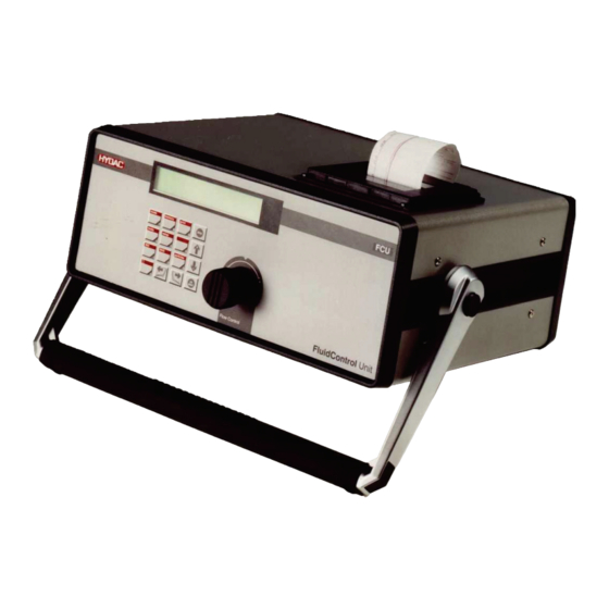
Description of the FCU Operating elements / Dimensions Item Code High pressure port = INLET Return port connection - OUTLET Switch - On/Off Electrical connection - 24 V DC Serial interface Control port Sealing cover Dot-matrix printer Display Keyboard Flow rate regulator Filter element FCU 8111 /-Aviation en(us) -
Page 21: Hydraulic Diagram
Hydraulic diagram Hydraulic diagram INLET OUTLET Item Code Optical sensor Flow rate sensor Flow rate control valve (adjustable) Filter Flow control valve FCU 8111 /-Aviation en(us) BEWA FCU8111 3690427a en-us 2017-01-23.doc 2017-01-23... -
Page 22: Fcu Function Description
FCU Function Description FCU Function Description Inlet Outlet Item Code Optical sensor Laser light source Photodetector Evaluation electronics Flow rate sensor Display Flow rate control valve (adjustable) Filter Flow control valve Serial interface Keyboard Relay Dot-matrix printer A continuous flow of oil runs through an optical sensor (1) comprised of a laser light source (2) and a photo receiver (3). - Page 23 FCU Function Description are both classified as measurement signals in accordance with particle size and counted by an evaluation electronics system (4). The measurement of the flow rate, which is necessary for specifying the contamination class, is carried out by a built-in flow rate sensor (5), the signals from which are also channeled to the electronic evaluation system (4).
- Page 24 FCU Function Description The evaluation electronics in the FCU continuously monitors for this purpose the following: • the particle sensor • the filter clogging indicator • the flow rate sensor • the power supply voltage • the internal evaluation electronics The contact from Relay 3 is always closed during normal operation.
-
Page 25: Adjusting The Carry And Support Handle
FCU Function Description Adjusting the carry and support handle The FCU has a carry and support handle to make transporting and working easier. To set the desired carrying or supporting position, continue as follows: Hold down both release buttons (a) at the same time and select the desired position of the carry and support handle (b). -
Page 26: Electrical Connection Of The Fcu
Electrical connection of the FCU Use the carry and support handle to position the FCU ergonomically in the working area. Ensure that the carry and support handle (b) audibly and noticeably locks into place. Electrical connection of the FCU The FCU is equipped with a battery. This allows network-independent measurement (with online print-out) for ≈... -
Page 27: Connecting The "Pc" Interface
Electrical connection of the FCU Connecting the "PC" interface You can communicate with a PC via this interface. This interface is designed in the standard version as RS232 and optionally as RS485. Serial RS 232 Interface (Standard) Signal function screen Transmission line Receiving line Ground... -
Page 28: Control" - Connecting The Control Port
Electrical connection of the FCU "Control" – Connecting the control port Contact assignment (switched position when the FCU is ready for operation) NC contact Relay 1, programmable by NO contact user Base contact NC contact Relay 2, programmable by NO contact user Base contact NC contact... -
Page 29: Relay Functions
Electrical connection of the FCU Relay Functions The following tables show the switched position of the relays in the various operating modes in keeping with the operating condition or measurement result. Relay 1 Relay 2 Measuremen Measurement After the first Flow rate t currently in stopped... - Page 30 Electrical connection of the FCU Relay 1 Relay 2 Within range Lower limit ≤ After Lower limit ≤ After measured switching the measured switching the value ≤ unit on or value ≤ upper unit on or upper limit starting a limit starting a measurement...
- Page 31 Electrical connection of the FCU Relay 1 Relay 2 Start or result Measuremen 5 consecutive After the first Flow rate of check t is currently measured measured within set measurement in progress values ≤ limit value is range after test and the available: cycle time ≥...
-
Page 32: Adjustable Limit Values
Electrical connection of the FCU Adjustable limit values Minimum Maximum M2: Switching limits FCU81xx 2 µm channel NAS 5 µm channel NAS 15 µm channel NAS 25 µm channel NAS 50 µm channel NAS 100 µm channel NAS 2 µm channel ISO 5 µm channel ISO 15 µm channel ISO Flow rate... -
Page 33: Fcu In Online Operation
FCU in online operation FCU in online operation WARNING Hydraulic systems are under pressure Danger of bodily injury Depressurize the system before performing ► any work on it. NOTICE If the OUTLET connection is closed or blocked The FCU will be damaged. Never seal the OUTLET connection. - Page 34 FCU in online operation To connect the FCU, proceed as follows:: Install the return hose in the OUTLET connection. Put the open end into a suitable container (e.g. hydraulic tank) and secure it from falling out. Set the flow rate control valve to a value of 3. Check the system pressure.
-
Page 35: Switching On The Fcu
When the FCU is switched on, various things are shown in the display, i.e. model no., firmware version, available memory, battery charge status, bus address and, possibly, error messages (cf. Error Messages / Troubleshooting chapter). Example: HYDAC FILTER SYSTEMS FCU 8111 V3.3x Memory: 25.4% 61 Battery: 13.49 V 80% Bus address: 1 Battery: 13.49 V 80%... -
Page 36: Operating The Fcu
Operating the FCU Operating the FCU The various operating menus of the FCU are described below. The following conventions are used: • Non-variable display texts are highlighted in light gray (printed version) or yellow (PDF file). • Variable display texts (user entries) are highlighted in bold (printed version) or... -
Page 37: Menu And Number Keys (Red)
Operating the FCU Menu and Number Keys (red) Select measurement mode setup Basic settings operation (Autostart, date, time, etc.) (with/without relay actuation) Editing measured value memory Display ISO code memory (This key responds only (name of the measuring when a measurement is point, measurement being carried out) intervals, deleting, etc.) -
Page 38: Fcu Menus
FCU menus FCU menus MODE - select operating mode In the Menu mode, select the operating mode in which the measurement is to be carried out. When the FCU is switched on, the operating mode last used last is preset. MODE mode M1: Measure... -
Page 39: Mode "M1: Measure
FCU menus MODE "M1: Measure" Mode M1 "Measurement" is used for measuring oil cleanliness without using the control functions. Typical Short-time measurement of system applications: cleanliness MODE "M2: Measuring and switching" Mode M2 "Measure + switch" can be used for measuring the cleanliness of the oil in the hydraulic system, at the same time offering the possibility of controlling limit relays for signaling purposes. -
Page 40: Mode "M4: Filtering From To" (Performance Of Automatic Filtration)
FCU menus MODE "M4: Filtering from to" (performance of automatic filtration) Mode M4 "Filter from ... to" enables the FCU to assume control of an external filtration unit. The external filtration unit will be controlled thereby in such a way that the oil cleanliness in the tank to be monitored will always be within the specified limits. -
Page 41: Memory Menu
FCU menus MEMORY Menu In the MEMORY menu you can set the storage of logs. The percentage shown in the display indicates how much of the memory has been used. 0.0% = Memory empty <-> 100 % Memory full. memory MEMORY 0,0 % Meas. -
Page 42: Designating The Measurement Point
FCU menus Designating the measurement point The measuring position designation is used for conveniently assigning a log to a measurement site at which a measurement is being or was performed. It is stored together with the measured results and appears on the log printouts. - Page 43 FCU menus The following characters can be selected: " & ‘ ä é è ê ö ü ß Insert character: start Press the keys simultaneously and a space will be inserted in front of the character just marked. Delete character: start Press the keys simultaneously and the...
-
Page 44: Setting The Averaging Interval
FCU menus Setting the averaging interval Entering an averaging interval enables the data quantity which accumulates during a measurement to be reduced. An averaging interval of > 0 min causes only the mean value of all measurements completed within this interval to be saved and printed out. The 0 min setting causes the averaging function to be deactivated. -
Page 45: Selective Deletion
FCU menus Selective deletion This menu item enables individual or several logs to be deleted. Various criteria are available for selecting the logs to be deleted. memory MEMORY 0.0% start Selective deletion Log selection: Number Log selection: Date Log selection: Meas. - Page 46 FCU menus No – Abort and exit stop Log selection: start Date dd.mm.yyyy specified value Date of log: is the date of dd.mm.yyyy the last log. Date of log: start dd.mm.yyyy Are you sure? OK = YES STOP = NO YES - The selected logs of start dd.mm.yyyy are deleted.
-
Page 47: Delete All
FCU menus Log selection: start Date + Measuring point dd.mm.yyyy specified value Date of log: is the date of dd.mm.yyyy the last log. Date of log: start dd.mm.yyyy Designation X specified value Measuring point: is the measuring Designation X point of the last log. -
Page 48: Change Meas. Point
FCU menus Change meas. – point This menu item enables the designation of a measuring point to be changed. memory MEMORY 0,0 % 0 start Change meas. point dd.mm.yyyy hh:mm Designation X dd.mm.yyyy hh:mm start Designation X Change measurement point: Designation X Change measurement point: start... -
Page 49: Setting The Memory Mode
FCU menus Setting the memory mode This menu item determines how the FCU behaves when its log memory is full. memory MEMORY 0,0 % 0 start Memory mode Overwrite Stop if full Confirm entries. start Abort and exit without saving. stop Overwrite Once 100 logs or 3000 measured values have been stored, the next log... -
Page 50: Print Menu
FCU menus PRINT menu The PRINT menu enables printouts to be initiated of stored logs, ongoing measurements, the table of contents and the parameter list. print PRINT Logs PRINT PRINT Contents PRINT PRINT All parameters PRINT Paper feed PRINT Online printout PRINT Print out, cancel Press this key to confirm the... -
Page 51: Logs
FCU menus Logs The stored logs from the FCU online operation can be output via the built-in dot-matrix printer. Various criteria are available for selecting the logs to be printed. print PRINT start Logs Log selection: Number Log selection: Date Log selection: Meas. - Page 52 FCU menus Printout of: Printout of: (only for print- out format "List") particle Printout of: The selected logs are printed. start Abort and exit stop FCU 81xx Particles Channel NAS 1 … 6 Log selection: start Date Date of log: dd.mm.yyyy Press this key to confirm the operating mode selected and to...
- Page 53 FCU menus Printout of: The selected logs are printed. start Abort and exit stop FCU 81xx Particles Channel NAS 1 … 6 Log selection: start Meas. point Measuring point: Designation X Press this key to confirm the operating mode selected and to start initiate measurement.
- Page 54 FCU menus Abort and exit stop FCU 81xx Particles Channel NAS 1 … 6 Log selection: start Date + Measuring point Date of log: dd.mm.yyyy Press this key to confirm the operating mode selected and to start initiate measurement. Measuring point: Designation X Press this key to confirm the operating mode selected and to...
- Page 55 FCU menus The selected logs are printed. start Abort and exit stop FCU 8111 /-Aviation en(us) BEWA FCU8111 3690427a en-us 2017-01-23.doc 2017-01-23...
-
Page 56: Print Contents
FCU menus FCU 81xx Particles Channel NAS 1 … 6 PRINT Contents A summary of the logs stored in memory is printed out. The following is output for each log: log number, measuring position designation, starting and stopping time, and number of log lines. PRINT print PRINT... -
Page 57: Paper Feed
FCU menus Paper feed The printer paper is transported ≈ 1 cm. print PRINT Paper feed Confirm entries and start paper feed. start Abort and exit. stop Online printout The measured values are output online on the dot-matrix printer. print PRINT start Online printout... -
Page 58: Print Out, Cancel
FCU menus Confirm entries start Abort and exit. stop Print out, cancel A current print operation is aborted. print PRINT Print out, cancel Confirm entries and start paper feed. start Abort and exit. stop LIMITS menu The LIMITS menu enables settings (limits) to be entered for the various operating modes. -
Page 59: Mode M2
FCU menus MODE M2 limits LIMITS M2: Relay 1 Press this key to confirm the operating mode selected and to start initiate measurement. Values according to the M2:R1 Measurement channel: measurement xx m chan. unit channel table on page 62. Press this key to confirm the operating mode selected and to start... - Page 60 FCU menus Abort and exit. stop FCU 8111 /-Aviation en(us) BEWA FCU8111 3690427a en-us 2017-01-23.doc 2017-01-23...
- Page 61 FCU menus limits LIMITS M2: Relay 2 Press this key to confirm the operating mode selected and to start initiate measurement. Values according to the M2:R2 Measurement channel: measurement xx m chan. unit channel table on page 62. Press this key to confirm the operating mode selected and to start initiate measurement.
-
Page 62: Measurement Channel Table
FCU menus Measurement channel table FCU 81xx 2 µm Channel 5 µm Channel 15 µm Channel 25 µm Channel 50 µm Channel 100 µm Channel 2 µm Channel 5 µm Channel 15 µm Channel Flow rate MODE M3 limits LIMITS start M3: Filter to Jump from value... -
Page 63: Mode M4
FCU menus MODE M4 limits LIMITS start M4: Filter from to Jump from value M4: Limit values: to value. / yy / zz ) Standard ( M4: Limit values: ( xx / yy / zz ) Standard M4: Limit values: ( xx / yy / zz ) Standard Press this key to confirm the... -
Page 64: Mode M5
FCU menus MODE M5 limits LIMITS start M5: Start delay t = 5 … 120 M5 Start delay: t [sec] t = 5 … 120 M5 Start delay: Press this key to confirm the operating mode selected and to start initiate measurement. -
Page 65: Setup Menu
FCU menus SETUP menu The SETUP menu enables settings to be entered which apply to several or all of the FCU’s operating modes. setup SETUP Autostart SETUP Abort at Q=0 SETUP Pump start delay SETUP Date / Time SETUP Bus address SETUP Operating hours SETUP... -
Page 66: Autostart
FCU menus Autostart This menu item enables a setting to be entered determining whether the FCU has to be started manually after having been switched on or whether it automatically performs a measurement in a preselected MODE. setup SETUP start Autostart Autostart: Autostart:... -
Page 67: Abort At Q=0
FCU menus Abort at Q=0 This menu item enables a setting to be entered determining how the FCU acts when the current flowing through the sensor drops to a value of “0” while a measurement is in progress. Measurement can either be interrupted or stopped altogether. An interrupted measurement automatically continues when a sufficient flow rate is present again. -
Page 68: Setting The Pump Start Delay
FCU menus Setting the pump start delay When conducting measurements with the aid of an external pump or an external filtration unit (e.g. OF5C), this function enables the user to operate the pump for a limited period of time within which a flow has to start at the FCU. -
Page 69: Setting The Date And Time
FCU menus Setting the date and time The date and time are displayed and can be changed. setup SETUP start Date / Time Selection Date: dd.mm.yyyy Date: dd.mm.yyyy Date: start dd.mm.yyyy Press this key to confirm the operating mode selected and to start initiate measurement. -
Page 70: Set Bus Address
FCU menus Set bus address The standard setting is 1; this setting should not be changed. If several units featuring DIN measurement bus interfaces (type code / - BUS) are connected to one bus, a bus address between 1 and 31 has to be allocated to each unit. An address may not be allocated twice. -
Page 71: Check The Battery Status
FCU menus Check the battery status The current battery charge is shown. setup SETUP start Battery state Battery voltage: 13.63 V Press this key to confirm the operating mode selected and to start initiate measurement. Abort and exit. stop FCU 8111 /-Aviation en(us) BEWA FCU8111 3690427a en-us 2017-01-23.doc 2017-01-23... -
Page 72: Powerup Menu
FCU menus POWERUP menu The POWERUP menu is only available when the FCU is powered up and as long as no measurement has been started. Settings are made here which are normally rarely changed. The POWERUP menu is accessed by simultaneously pressing the keys. - Page 73 FCU menus Abort and exit the Powerup stop menu FCU 8111 /-Aviation en(us) BEWA FCU8111 3690427a en-us 2017-01-23.doc 2017-01-23...
-
Page 74: Setting The Measured Volume
FCU menus Setting the measured volume The volume that is analyzed for the determination of a measured value can be set here. Permitted values range from 10 ... 100. Applying the submenu selected. Test volume start Depending Measurement volume: on the key, 100 ml the value increased /... -
Page 75: Fcu Display
FCU Display FCU Display FCU 8110 FCU 8210 M1 68% M1 68% Q: 50ml 19/15/10 Q: 50ml 19/15/10 SAE/NAS M1 68% SAE(A) M1 68% NAS(2) Q: 50ml NAS(5) Q: 50ml SAE(B) Partikel M1 68%C 4µm: 43421 M1 68%D 2µm: 43421 Q: 50ml 6µm: 8725 Q: 50ml 5µm:... - Page 76 FCU Display If the determined particle count lies above the specified display range (see page 92), >25 or >15 is shown in all particle size ranges as the particle count. One can select between differential and cumulative displays of numbers of particles by using the keys .
-
Page 77: Brief Overview Of The Menu Structure
Brief Overview of the Menu Structure Brief Overview of the Menu Structure MODE M1: Measure M2: Measure + Switch M3: Filter to M4: Filter from to M5: Measure+Autostop MEMORY Meas. point Measuring point xx Designation xx Averaging interval X min. Selective deletion Number Log number:... - Page 78 Brief Overview of the Menu Structure M2: R2 Meas. Channel: See table, page 62. M2: R2 Switch func: No function Within range Outside range Exceed Fall below M3: Filter to M3: Limits: ( xx / xx / xx ) Unit M4: Filter from to M4: Limit values: ...
-
Page 79: Error Messages And Troubleshooting
Error Messages and Troubleshooting Error Messages and Troubleshooting Error message Cause(s) Remedy Invalid parameter You have entered a value Display the permitted which is outside the value ranges using the permitted value range (e.g. NAS 23). keys scrolling above the maximum values. - Page 80 Error Messages and Troubleshooting Error message Cause(s) Remedy Number of The self-monitoring The defective logs are defective logs: function of the FCU has deleted automatically. detected a check sum After the next power up, error for one or more this message is not stored logs.
- Page 81 Error Messages and Troubleshooting Error message Cause(s) Remedy Use power supply The rechargeable The batteries require a batteries are dead. charging time of ≈ 11 hours. You can operate the FCU using a connected power supply. Flow rate error! There is no oil flowing Check the hydraulic through the particle connections.
- Page 82 Error Messages and Troubleshooting Error message Cause(s) Remedy Reload languages The internal memory for Download the FCU languages has been languages to the FCU partially changed due to again using the PC an internal fault. software package FluMoS. The internal back-up battery is dead.
-
Page 83: Performing Maintenance
Performing maintenance Performing maintenance Carry out the specified configuration, maintenance and inspection work every six months or, at the latest, when an error message or malfunction makes it necessary. Disconnect the FCU from the power supply when performing any maintenance, inspection or repair work. Once maintenance work is complete, check that the FCU is still working properly. - Page 84 Performing maintenance Unscrew the screw plug with an Allen wrench (size 6 mm) by turning it counterclockwise. Pull the filter element out upwards with needle-nose pliers and dispose of the old filter insert properly in an environmentally correct manner. Check the now visible O-ring for damage.
- Page 85 Performing maintenance Check the O-ring on the sealing cover for damage. Replace it if necessary. Insert and manually screw in the sealing cover clockwise. Tighten the sealing cover with a 19 mm ring spanner. 10. The filter element change is now complete.
-
Page 86: Replacing The Paper Roll / Ink Ribbon In The Dot-Matrix Printer
Performing maintenance Replacing the paper roll / ink ribbon in the dot-matrix printer To change the paper roll / ink ribbon, proceed as follows: Switch off the FCU off at the switch. Lift the cover of the dot-matrix printer. Remove the ink ribbon from the dot- matrix printer in an upward direction. - Page 87 Performing maintenance Cut the start of the new paper roll into a point Remove the axis from the used paper roll and place it in the new paper roll. 10. Feed the start of the new paper roll into the slot. 11.
- Page 88 Performing maintenance 15. Thread the ink ribbon over the start of the paper roll. 17. Press the ink ribbon into the dot- matrix printer using two fingers. 18. Feed the start of the paper through the slot in the cover. 19.
-
Page 89: Disposing Of The Fcu
Disposing of the FCU Disposing of the FCU Dispose of the packaging material in an environmentally friendly manner. After dismantling the device and separating its various materials, dispose of it in an environmentally friendly manner. Calibrating the FCU We recommend that the FCU be recalibrated every year. You will receive a calibration certificate at the time of each calibration. -
Page 90: Spare Parts
Spare parts Spare parts FCU 8xx1 (version for HFD fluids) (example: Skydrol, Fyrquel, Hyjet) Part no. Article designation 3523517 Filter element replacement set, consisting of: 1x filter element, 2x O-ring, 1x support ring (HFD-R fluids) 629037 O-ring for cover 417447 Support ring for sealing cover 6003730 High-pressure measuring hose DN 2, 5000 mm long (HFD-R fluid) -
Page 91: Accessories
Accessories Accessories Part no. Code Carrying case, including filter element replacement set, 3799018 2 rolls of paper, 1 ink ribbon for dot-matrix printer FluMoS light Software 3355176 (download available free of charge at www.hydac.com) 3371637 FluMoS Professional Software 3053829 LabView Driver Package (Software) 3143926 Windows Driver Package (Software) FCU 8111 /-Aviation... -
Page 92: Technical Data
Technical data Technical data Measured value display Continuous view in LCD display Self-diagnosis Continuous self-monitoring with error indication in LCD display Calibration FCU 81xx: ISO 4402 / NAS 1638 FCU 81xx: Particle size channels: 2µm / 5µm / 15µm / 25µm / 50µm / 100µm Measurement range (calibrated): FCU 81xx:... - Page 93 Technical data Power consumption 25 Watt max. Battery-powered operating duration ≈ 6 hours (online pressure off) Built-in printer Dot-matrix printer Serial interface RS 232 (for models /-BUS: RS 485) with 15-pin Sub D plug Ambient temperature range 0 … 55° C / 32 … 131° F Storage temperature range -20 …...
-
Page 94: Appendix
Appendix Appendix Explanation of the measuring technology terms used Single This refers to the analysis of the contamination of a measurement: specified sample quantity (measurement volume). The result of a single measurement is the measured value. Measuring point The name of the location at which the FCU is connected to the hydraulic system. - Page 95 Appendix Log header: The log header contains: A log number (a consecutive log number is automatically generated every time a measurement sequence is initiated). The designation of the measurement point (can be entered by the user), date + time of the beginning and end of the measurement sequence (generated automatically) Averaging interval Number of log lines Measurement volume Example:...
-
Page 96: Customer Service / Service Stations Around The World
Appendix Customer Service / Service stations around the world Shipping address for calibration and repair: Germany HYDAC Service GmbH Product Support, Werk 13 Friedrichsthaler Straße 15A 66540 Neunkirchen-Heinitz Telephone: ++49 (0) 6897 509 883 Telefax: ++49 (0) 6897 509 324 E-Mail: service@hydac.com HYDAC Technology Corporation, HYCON Division... -
Page 97: Brazil
Appendix Brazil HYDAC TECNOLOGIA LTDA Estrada Fukutaro Yida, 225 CEP 09852-060 Cooperativa BR-São Bernardo do Campo – SÃO PAULO Telephone: +55 11 - 4393.6600 Telefax: +55 11 - 4393.6617 E-Mail: hydac@hydac.com.br Homepage www.hydac.com.br China HYDAC TECHNOLOGY (SHANGHAI) LIMITED 28 Zhongpin Lu Shanghai Minhang Economic &... -
Page 98: Overview - Iso 4406 / Sae As 4059 And Nas 1638 Classes
Appendix Overview - ISO 4406 / SAE AS 4059 and NAS 1638 classes ISO 4406:1999 In ISO 4406:1999, particle counts are determined cumulatively, i.e. > 4 µm >6 µm and >14 µm (manually by filtering the fluid through an analysis membrane or automatically using particle counters) and allocated to measurement references. -
Page 99: Overview Of The Differences Between Iso 4406:1987 And Iso 4406:1999
Appendix Note: increasing the measurement reference by 1 causes the particle count to double. Example: ISO code 18 / 15 / 11 means: Cleanliness class Particle count / 100 ml Size ranges 130,000 – 250,000 > 4 µm (c) 16,000 – 32,000 >... -
Page 100: Sae As 4059
Appendix SAE AS 4059 Like ISO 4406, SAE AS 4059 describes particle concentrations in liquids. The analysis methods can be applied in the same manner as ISO 4406:1999. The SAE cleanliness classes are based on particle size, number and distribution. The particle size determined depends on the measurement process and calibration;... -
Page 101: Cleanliness Codes According To Sae
Appendix Cleanliness codes according to SAE Absolute particle count larger than a defined particle size Example: cleanliness class to AS 4059:6 The maximum permissible particle count in the individual size ranges is bold- faced in the above table. Cleanliness class to AS 4059:6B Size B particles may not exceed the maximum number indicated for code 6 6 B = max. -
Page 102: Nas 1638
Appendix NAS 1638 Like ISO 4406, NAS 1638 describes particle concentrations in liquids. The analysis methods can be applied in the same manner as ISO 4406:1999. In contrast to ISO 4406, certain particle ranges are counted in NAS 1638 and attributed to measurement references. -
Page 103: Factory Default Settings
Appendix Factory default settings FCU 81xx POWERUP Menu Language German Test volume 100 ml MEMORY Menu Meas. point HYDAC FCU 8110 Averaging interval 0 min Memory mode Overwrite PRINT menu Online printout Printout format List Printout of Particles Log duration 1 h / page (30 cm) SETUP menu Autostart... -
Page 104: Glossary
Appendix Glossary Explanation of the measuring technology terms used Single This refers to the analysis of the contamination of a measurement: specified sample quantity (measurement volume). The result of a single measurement is the measured value. Measuring point The name of the location at which the FCU is connected to the hydraulic system. - Page 105 Appendix Log header: The log header contains: A log number (a consecutive log number is automatically generated every time a measurement sequence is initiated). The designation of the measurement point (can be entered by the user), date + time of the beginning and end of the measurement sequence (generated automatically) Averaging interval Number of log lines Measurement volume Example:...
-
Page 106: Index
Appendix Index Accessories 91 Filter 7, 13, 19, 20, 21, 22, 38, 39, 40, 58, 62, 63, accident prevention 11 66, 77, 78, 83, 90 Ambient temperature range 93 Filter element 20, 90 Autostart 37, 65, 66, 78, 103 Filter from to 38, 58, 63, 66, 77, 78 Auxiliary personnel 14 Filter to 38, 39, 58, 62, 66, 77, 78 Averaging interval 41, 44, 77, 95, 103, 105... - Page 107 Appendix Limit value 59, 61, 62, 63, 78, 103 Proper/Designated Use 12 limit value switch 23 Protection class 93 LIMITS 40, 58, 59, 61, 62, 63, 64, 77, 103 Publisher 2 Log duration 103 Pump 65, 68, 78, 103 Log header 95, 105 Pump start delay 65, 68, 78, 103 Log line 95, 105 Log number 45, 51, 77...
- Page 108 HYDAC FILTER SYSTEMS GMBH Industriegebiet Postfach 1251 66280 Sulzbach/Saar 66273 Sulzbach/Saar Germany Germany Phone: +49 (0) 6897 509 01 Central Fax: +49 (0) 6897 509 846 (Technical Department) Fax: +49 (0) 6897 509 577 (Sales Department) Internet: www.hydac.com E-Mail: filtersystems@hydac.com...
Need help?
Do you have a question about the FluidControl FCU 8111 and is the answer not in the manual?
Questions and answers