
Related Manuals for Campbell Sensor CS240


Summary of Contents for Campbell Sensor CS240
- Page 1 CS240 and CS240DM PT-1000 Class A, Back-of-Module Temperature Sensors Revision: 5/18 Copyright © 2017 – 2018 Campbell Scientific, Inc.
- Page 4 (780) 454-2655. Campbell Scientific (Canada) Corp. is unable to process any returns until we receive this form. If the form is not received within three days of product receipt or is incomplete, the product will be returned to the client at the client’s expense.
- Page 5 Periodically (at least yearly) check electrical ground connections. WHILE EVERY ATTEMPT IS MADE TO EMBODY THE HIGHEST DEGREE OF SAFETY IN ALL CAMPBELL SCIENTIFIC PRODUCTS, THE CLIENT ASSUMES ALL RISK FROM ANY INJURY RESULTING FROM IMPROPER INSTALLATION, USE, OR MAINTENANCE OF TRIPODS, TOWERS, OR ATTACHMENTS TO TRIPODS AND TOWERS SUCH AS SENSORS, CROSSARMS, ENCLOSURES, ANTENNAS, ETC.
- Page 6 PLEASE READ FIRST About this manual Please note that this manual was originally produced by Campbell Scientific Inc. (CSI) primarily for the US market. Some spellings, weights and measures may reflect this origin. Some useful conversion factors: Area: 1 in...
-
Page 8: Table Of Contents
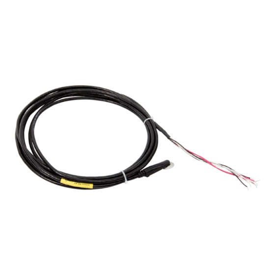
Table of Contents PDF viewers: These page numbers refer to the printed version of this document. Use the PDF reader bookmarks tab for links to specific sections. 1. Introduction ..............1 2. Precautions ..............1 3. Initial Inspection ............2 4. - Page 9 Table of Contents B. Example Programs ..........B-1 CS240 Two-Wire Configuration Programs ........B-1 CS240 Four-Wire Configuration Programs ........B-4 CS240DM Program ................. B-7 C. Sensor Material Properties ........C-1 3M 9485PC Adhesive ..............C-1 Figures 5-1. CS240/CS240DM Temperature Sensor ..........5 7-1.
-
Page 10: Introduction
Campbell Scientific dataloggers. The CS240DM has a digital RS-485 output that can be directly read by a MeteoPV, CR6, CR1000X, or Modbus RTU RS-485 network. Other Campbell Scientific dataloggers can use an MD485 multidrop interface to read the CS240DM output. -
Page 11: Initial Inspection
CS240 and CS240DM PT-1000 Class A, Back-of-Module Temperature Sensors Initial Inspection Upon receipt of the sensor, inspect the packaging and contents for damage. • File damage claims with the shipping company. • The model number, cable length, wiring diagrams, and cable resistance (CS240 only) are printed on a label at the connection end of the cable. - Page 12 CS240 and CS240DM PT-1000 Class A, Back-of-Module Temperature Sensors Repeat step three for other sensors you want to measure. In Output Setup, type the scan rate, a meaningful table name, and the Data Output Storage Interval.
-
Page 13: Overview
If the temperature may exceed 70 °C, Kapton tape is also required to secure the sensor. The CS240DM includes a Campbell Scientific precision analog-to-digital, smart-sensor module for making the measurements. The module design is optimized for the class A PRT that minimizes self-heating and lead-wire resistance. -
Page 14: Specifications
Self-adhesive backing for easy mounting lasts decades • CS240 has 2-wire or 4-wire configurations to satisfy accuracy even at long cable lengths CS240 compatible with Campbell Scientific CRBasic dataloggers: • CR300 series, CR6 series, CR800 series, CR1000, CR1000X series, CR3000, and CR5000 CS240DM compatible with Campbell Scientific CRBasic dataloggers: •... - Page 15 CS240 and CS240DM PT-1000 Class A, Back-of-Module Temperature Sensors CS240 Measuring Current: 0.1 to 0.3 mA Disk Diameter: 2.54 cm (1.0 in) Overall Sensor Length: 6.35 cm (2.5 in) Overmolded Joint Dimensions Width: 1.12 cm (0.44 in) Height: 1.47 cm (0.58 in) Length: 5.72 cm (2.25 in) Cable Diameter:...
-
Page 16: Installation
CS240 and CS240DM PT-1000 Class A, Back-of-Module Temperature Sensors CS240DM Cable Features: High flex construction with jacket for pulling through conduit Jacket Material: Black semi-gloss PVC, UL VW-1 sunlight resistant for outdoor use; weld spatter and oil resistant Nominal Wire Diameter: 0.61 mm (0.024 in) Agency Approvals: UL AWM Style 2463 and NEC/CEC... -
Page 17: Strain Relief Label On The Cable
CS240 and CS240DM PT-1000 Class A, Back-of-Module Temperature Sensors Place the other strips of tape on the first strip of tape and rub the tape surface to remove bubbles. These strips of tape should be perpendicular to the first strip of tape—forming an “H” (FIGURE 7-2). To secure the sensor to the module surface, remove the paper from the bottom of the disk and adhere the disk to the PV module (Section 7.1, Placement on a Photovoltaic (PV) Module... -
Page 18: Strain Relief Of Cs240Dm Analog-To-Digital Module
CS240 and CS240DM PT-1000 Class A, Back-of-Module Temperature Sensors FIGURE 7-2. Proper Kapton Tape Usage 7.2.3 Strain Relief of CS240DM Analog-to-Digital Module The CS240DM has an analog-to-digital, smart-sensor module incorporated that needs to be secured to the side of PV module. Use two cable tie tabs and cable ties to do this. -
Page 19: Cs240-To-Datalogger Wiring
CS240 and CS240DM PT-1000 Class A, Back-of-Module Temperature Sensors FIGURE 7-3. 2-Wire Circuit Diagram FIGURE 7-4. 4-Wire Circuit Diagram 7.3.2 CS240-to-Datalogger Wiring The dataloggers can measure the CS240 by using a 2-wire or 4-wire configuration (TABLE and TABLE 7-2). The 2-wire configuration accuracy decreases, relative to the 4-wire, as a function of the cable length. -
Page 20: Cs240Dm Wiring
Clear/ ⏚ (analog ground) Shield Shield U terminals are automatically configured by the measurement instruction. 7.3.3 CS240DM Wiring Connections to Campbell Scientific dataloggers are given in TABLE 7-3. The wiring for the CS240DM is also available in Device Configuration Utility. -
Page 21: Datalogger Programming
CS240 and CS240DM PT-1000 Class A, Back-of-Module Temperature Sensors TABLE 7-3. Wire Color, Function, and Datalogger Connection for the CS240DM Datalogger Wire Color Wire Function Connection Terminal White/ 12 V Power Brown Striped Brown Ground (Power) C (control terminal) Blue RS-485 A- (D0) White/ RS-485 B+ (D1) -
Page 22: Converting Resistance Measurement To Temperature
7.4.2 CS240DM Programming NOTE Programming basics for the CR6 and CR1000X dataloggers are provided in this section. Contact Campbell Scientific if using a datalogger that requires an MD485 interface. A CR6 or CR1000X datalogger programmed as a Modbus Master can retrieve the values stored in the CS240DM Input Registers (TABLE 7-4). -
Page 23: Operation
CS240 and CS240DM PT-1000 Class A, Back-of-Module Temperature Sensors The SerialOpen instruction has the following syntax: SerialOpen (ComPort, Baud, Format, TXDelay, BufferSize, Mode ) The Format is typically set to logic 1 low; even parity, one stop bit, 8 data bits. The Mode parameter should configure the ComPort as RS-485 half-duplex, transparent. -
Page 24: Cs240Dm Long Cable Lengths
Use low capacitance, low resistance, screened cable (as fitted by • Campbell Scientific) to reach distances of several hundred meters. • Ensure that the power ground cable has low resistance and is connected to the same ground reference as the datalogger control terminals. -
Page 25: Maintenance And Troubleshooting
CS240 and CS240DM PT-1000 Class A, Back-of-Module Temperature Sensors The settings are changed in the Holding Registers tab. Except for the Modbus Address, the default values are typical for most Modbus systems and therefore rarely need to be changed. The values stored are shown in the Input Registers tab. Maintenance and Troubleshooting NOTE For all factory repairs, customers must get an RMA number. -
Page 26: Importing Short Cut Code Into Crbasic Editor
Appendix A. Importing Short Cut Code Into CRBasic Editor This tutorial shows: Importing a Short Cut program into a program editor for additional • refinement Importing a wiring diagram from Short Cut into the comments of a • custom program Short Cut creates files, which can be imported into CRBasic Editor. -
Page 28: Example Programs
Appendix B. Example Programs B.1 CS240 Two-Wire Configuration Programs CRBasic Example B-1. CR300 2-Wire Configuration for Measuring the CS240 'CR300 Series 'Declare Variables and Units CS240X CS240Rs Public CS240T_C Units CS240T_C=Deg C 'Define Data Tables DataTable(Hourly,True,-1) DataInterval(0,60,Min,10) Sample(1,CS240T_C,FP2) EndTable 'Main Program BeginProg 'Main Scan Scan(5,Sec,1,0) - Page 29 Appendix B. Example Programs CRBasic Example B-2. CR6 2-Wire Configuration for Measuring the CS240 'CR6 Series 'Declare Variables and Units CS240X CS240Rs Public CS240T_C Units CS240T_C=Deg C 'Define Data Tables DataTable(Hourly,True,-1) DataInterval(0,60,Min,10) Sample(1,CS240T_C,FP2) EndTable 'Main Program BeginProg 'Main Scan Scan(5,Sec,1,0) 'CS240 (2-wire) Class A RTD Back of PV Module Temperature Sensor measurement 'CS240T_C' BrHalf(CS240X,1,mV200,U2,U1,1,350,True,0,60,1,0) 'Convert ratio to ohms and remove cable resistance...
- Page 30 Appendix B. Example Programs CRBasic Example B-3. CR1000X 2-Wire Configuration for Measuring the CS240 'CR1000X Series 'Declare Variables and Units CS240X CS240Rs Public CS240T_C Units CS240T_C=Deg C 'Define Data Tables DataTable(Hourly,True,-1) DataInterval(0,60,Min,10) Sample(1,CS240T_C,FP2) EndTable 'Main Program BeginProg 'Main Scan Scan(5,Sec,1,0) 'CS240 (2-wire) Class A RTD Back of PV Module Temperature Sensor measurement 'CS240T_C' BrHalf(CS240X,1,mV200,1,Vx1,1,350,True,0,60,1,0) 'Convert ratio to ohms and remove cable resistance...
-
Page 31: Cs240 Four-Wire Configuration Programs
Appendix B. Example Programs B.2 CS240 Four-Wire Configuration Programs CRBasic Example B-4. CR300 4-Wire Configuration for Measuring the CS240 'CR300 Series 'Declare Variables and Units CS240X CS240Rs Public CS240T_C Units CS240T_C=Deg C 'Define Data Tables DataTable(Hourly,True,-1) DataInterval(0,60,Min,10) Sample(1,CS240T_C,FP2) EndTable 'Main Program BeginProg 'Main Scan Scan(5,Sec,1,0) - Page 32 Appendix B. Example Programs CRBasic Example B-5. CR6 4-Wire Configuration for Measuring the CS240 'CR6 Series 'Declare Variables and Units CS240X CS240Rs Public CS240T_C Units CS240T_C=Deg C 'Define Data Tables DataTable(Hourly,True,-1) DataInterval(0,60,Min,10) Sample(1,CS240T_C,FP2) EndTable 'Main Program BeginProg 'Main Scan Scan(5,Sec,1,0) 'CS240 (4-wire) Class A RTD Back of PV Module Temperature Sensor measurement 'CS240T_C' BrHalf4W(CS240X,1,mV200,mV200,U3,U1,1,350,True,True,0,60,1,0) 'Convert ratio to ohms...
- Page 33 Appendix B. Example Programs CRBasic Example B-6. CR1000X 4-Wire Configuration for Measuring the CS240 'CR1000X Series 'Declare Variables and Units CS240X CS240Rs Public CS240T_C Units CS240T_C=Deg C 'Define Data Tables DataTable(Hourly,True,-1) DataInterval(0,60,Min,10) Sample(1,CS240T_C,FP2) EndTable 'Main Program BeginProg 'Main Scan Scan(5,Sec,1,0) 'CS240 (4-wire) Class A RTD Back of PV Module Temperature Sensor measurement 'CS240T_C' BrHalf4W(CS240X,1,mV200,mV200,1,Vx1,1,350,True,True,0,60,1,0) 'Convert ratio to ohms...
-
Page 34: Cs240Dm Program
Appendix B. Example Programs B.3 CS240DM Program CRBasic Example B-7. CS240DM RS-485 Modbus Program 'CR6 Series Datalogger Public PTemp Public batt_volt Public ResultCode(4) Public CS240DM(20) Public AveTemp(4) Public SD_Temp Public AvgTemp Alias ResultCode(1) = CS240DM_1_ResultCode Alias ResultCode(2) = CS240DM_2_ResultCode Alias ResultCode(3) = CS240DM_3_ResultCode Alias ResultCode(4) = CS240DM_4_ResultCode... - Page 35 Appendix B. Example Programs StdDevSpa (SD_Temp,4,AveTemp()) CallTable Hourly NextScan EndProg...
-
Page 36: 9485Pc Adhesive
Appendix C. Sensor Material Properties The sensor consists of 6061 aluminum (clear anodized), RTD, 3M9485PC adhesive, and Santoprene jacketed cable. ® C.1 3M 9485PC Adhesive Humidity Resistance: High humidity has a minimal effect on adhesive performance. Bond strengths are generally higher after exposure for 7 days at 90 °F (32 °C) and 90% relative humidity. - Page 39 Campbell Scientific Worldwide Offices Australia Germany Location: Garbutt, QLD Australia Location: Bremen, Germany Email: Email: info@campbellsci.com.au info@campbellsci.de Website: www.campbellsci.com.au Website: www.campbellsci.de Brazil South Africa Location: São Paulo, SP Brazil Location: Stellenbosch, South Africa Email: andread@campbellsci.com.br Email: sales@csafrica.co.za Website: Website: www.campbellsci.com.br www.campbellscientific.co.za...
Need help?
Do you have a question about the Sensor CS240 and is the answer not in the manual?
Questions and answers