2VV VENESSE Comfort VCV-B-25E Installation Manual
Hide thumbs
Also See for VENESSE Comfort VCV-B-25E:
- Operation and maintenance manual (14 pages) ,
- Manual (10 pages)

Related Manuals for 2VV VENESSE Comfort VCV-B-25E


Summary of Contents for 2VV VENESSE Comfort VCV-B-25E
- Page 1 Comfort VENESSE VCV-B-25E, VCV-B-25F, VCV-B-25W, VCV-B-25S Full manual installation...
-
Page 2: Before You Begin
1. BEFoRE YoU BEGin symbol Meaning ATTENTION! Warning/caution DO NOT OVERLOOK! Important instructions YOU WILL NEED Practical tips and information TECHNICAL INFORMATION More detailed technical information Refer to other parts/sections of the manual Before installation, thoroughly read the section “safe use of air curtains”. It con- tains all instructions on the safe and correct use of the product. -
Page 3: Check The Shipment
2. UnPaCKinG 2. UnPaCKinG 2.1 CHECK tHE sHiPMEnt 2.2 UnPaCK tHE aiR CURtain • After delivery, immediately check to see if the packaged product is damaged. If the packaging is damaged contact the delivery service. If the complaint is not filed in time, your claim may not be valid later. -
Page 4: Main Parts
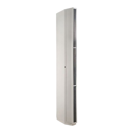
3. Main PaRts Upper cover Service cover Anchor stand covers Locking bolt Exhaust grid Anchor stand – part 2 Anchor stand – part 1 4. DiMEnsions Anchor stand dimensions (mm) Air curtain dimensions (mm) -
Page 5: Technical Parameters
5. tECHniCal PaRaMEtERs Heater Max. width Heater type noise*** power Weight door* output output output supply [dB(a)] [kW] [V/a] [V/a] [kg] [m³/h] VCV-B-25s 5500 230/6.5 VCV-B-25E 5400 55.5 400/33.5 230/6.5 4 (7**) VCV-B-25F 5400 55.5 40/50 230/6.5 VCV-B-25W 5100 41.1**** 230/6.5 The distance at which the average velocity of the air current flow drops to 2m/s.For optimal conditions and... - Page 6 5. tECHniCal PaRaMEtERs air curtains with a water coil for a water temperature gradient of 80º/60° C and at an intake air temperature of +18° C output type air output Heat output temperature Water flow Pressure loss [m³/h] [kW] [°C] [l/s] [kPa] VCV-B-25W...
-
Page 7: Installation
6. installation 6. installation 6.1 CHoosE tHE installation sitE • only nonflammable materials (those that do not burn, smoulder or carbonise) or fire- 6.1-1 installed dimensions resistant materials (those that do not burn, but mainly smoulder, e.g., plaster board) can be kept within 100 mm in any direc- tion of the air curtain. - Page 8 6. installation 6. installation 6.1 CHoosE tHE installation sitE 6.1-4 secure the anchor stand 4 size M5 bolts (included in delivery) • At least • A No. 10 wrench (part 1) to the floor. 5 x M8 6.1-6 slide the air curtain onto its stand (part 1).
- Page 9 6. installation 6.1-7 Cover the anchor stand • The water intake and outlet positions can be chosen as you wish. (left-right orientation) Put the anchor stand covers on and bolt them • the maximum water temperature is down horizontally with 4 anchor bolts. +100°...
-
Page 10: Connecting The Electrical
6. installation 6. installation 6.3 ConnECtinG tHE ElECtRiCal Minimal cable dimensions: sUPPlY Cable type [ks x mm2] VCV-B-25s 3 x 1.5 VCV-B-25E 5 x 6 VCV-B-25F 5 x 10 VCV-B-25W 3 x 1.5 • the air curtain’s electrical connection must be based on a professional design by a qua- lified electrical systems engineer. -
Page 11: Install The Control Panel
6. installation 6. installation 6.4 install tHE ContRol PanEl • the electrical parameters are shown on the manufacturer’s label, which is located under the air curtain’s service cover. Air curtain Type U = Voltage = Net current = Frequency P = Output n = Speed m = Weight ph = Phase... - Page 12 6. installation 6.4-1 Loosen the bolt on the under side of the control panel. 6.4-2 Open the box and remove the front cover from the upper latches. Retain the back part of the box.. 6.4-3 Cut a passage for the communication cable. Use the areas moulded for this purpose.
- Page 13 6. installation • The cable should not be routed with power cables and should be located a sufficient dis- tance away from them. • Take care that during connection the connector snaps into place. - when mounting the cable to the wall, make sure its insulation is not damaged - If you do not connect the cable immediately after mounting the control panel and cur- tain, cover the connector or cable ends with insulation tape, in order to prevent possible mechanical damage or short-circuiting.
- Page 14 6. installation 6.5-1 Door switch DK - Isolated switching contact with a maximum voltage of 12V. Cable - Dual-core cable with a diameter of 0.5 mm. - Maximum length: 50 m. Connector on the air curtain: 17/18 17 18 not included in delivery. 6.5-2 timer switch sH - Isolated switching contact with a maximum voltage of 230V.
-
Page 15: Room Thermostat
6. installation 6.5.-3 Room thermostat • Room thermostat for the switching of the device depending on the tem- perature set in the measured location • Switching contact without potential with max. voltage 230 V. • CABLE: Twin core cable with a diameter of min. 0.5 mm. Maximum length 50 m. air curtain clamps: tER / lopen not included. - Page 16 6. installation 6.6 ConnECtinG MUltiPlE aiR CURtains — CHaininG The VENESSE Comfort air curtain is designed to allow up to six air curtains to be installed together as a chain and operated from one control panel. Select any air curtain as the controller (MASTER) and connect the control panel to it. Then connect to this air curtain the air curtains that will be controlled (SLAVE).
-
Page 17: Initial Start-Up
7. initial staRt-UP 7.1-2 turning the air curtain on and off Press the button to turn the air curtain Before putting the air curtain into operation, on Press the same button to turn the air curtain check the following: off. •... - Page 18 7.2 sEt aiR FloW DiRECtion 2VV, s.r.o., Poděbradská 289, This is set by tilting the air curtain’s fan louvers 530 09 Pardubice, in the desired direction. Czech Republic internet: http://www.2vv.cz/contact.distribution.php Copyright (c) 2005-2007 2VV s.r.o. All rights re- served. 01-0205-0110-00...
Need help?
Do you have a question about the VENESSE Comfort VCV-B-25E and is the answer not in the manual?
Questions and answers