
Related Manuals for Black Box ACX1MR


Summary of Contents for Black Box ACX1MR
- Page 1 USER MANUAL ACX1MR, ACX1MT DISPLAYPORT 1.1 SERIES DKM KVM DP MODULAR EXTENDERS 24/7 TECHNICAL SUPPORT AT 1.877.877.2269 OR VISIT BLACKBOX.COM...
-
Page 2: Table Of Contents
NEED HELP? LEAVE THE TECH TO US LIVE 24/7 TABLE OF CONTENTS TECHNICAL SUPPORT 1.877.877.2269 CONTENTS SAFETY INSTRUCTIONS ....................................6 1. SPECIFICATIONS ......................................7 1.1 INTERFACES ....................................... 7 1.1.1 DISPLAYPORT ........................................7 1.1.2 USB-HID ..........................................7 1.1.3 PS/2 ............................................7 1.1.4 USB 2.0 (TRANSPARENT) ....................................8 1.1.5 RJ-45 (INTERCONNECT) ....................................8 1.1.6 FIBER SFP TYPE LC (INTERCONNECT) ................................8 1.1.7 SERIAL INTERFACE ......................................8... - Page 3 2.6.12 MODEL ACX2MR-DP11H-2C/ACX2MT-DP11H-2C ............................31 2.6.13 MODEL ACX2MR-DP11H-2C/ACX2MT-DP11H-2C ........................... 32 2.6.14 MODEL ACX2MR-DP11H-SM/ACX2MT-DP11H-SM ..........................32 2.6.15 MODEL ACX2MR-DP11H-2S/ACX2MT-DP11H-2S ............................ 33 2.6.16 MODEL ACX1MT-HID/ACX1MR-HID ................................33 2.6.17 MODEL ACX1MT-EU/ACX1MR-EU ................................34 2.6.18 MODEL ACX1MT-EU2/ACX1MR-EU2 ................................34 2.6.19 MODEL ACX1MT-AR/ACX1MR-AR ................................34 2.6.20 MODEL ACX1MT-ARP/ACX1MR-ARP ................................35 2.6.21 MODEL ACX1MT-DA/ACX1MR-DA ................................35...
- Page 4 NEED HELP? LEAVE THE TECH TO US LIVE 24/7 TABLE OF CONTENTS TECHNICAL SUPPORT 1.877.877.2269 3. INSTALLATION ......................................44 3.1 PACKAGE CONTENTS .....................................44 3.2 SYSTEM SETUP ....................................... 46 3.2.1 KVM EXTENDER SETUP ....................................46 3.2.2 SETUP OF UPGRADE MODULES .................................. 46 3.3 EXAMPLE APPLICATIONS ..................................
- Page 5 NEED HELP? LEAVE THE TECH TO US LIVE 24/7 TABLE OF CONTENTS TECHNICAL SUPPORT 1.877.877.2269 APPENDIX A. REGULATORY INFORMATION .............................64 A.1 CE DECLARATION OF CONFORMITY ..............................64 A.2 FCC CLASS A STATEMENT ..................................64 A.3 PRODUCT SAFETY ....................................64 A.4 WEEE ......................................... 64 A.5 ROHS 2 ........................................
-
Page 6: Safety Instructions
Š Do not attempt to open or repair a power supply unit. Š Š Do not attempt to open or repair the KVM Extender. There are no user-serviceable parts inside. Š Š Contact Black Box at 877-877-2269 or info@blackbox.com if there is a fault. Š 1.877.877.2269 BLACKBOX.COM... -
Page 7: Specifications
NEED HELP? LEAVE THE TECH TO US LIVE 24/7 CHAPTER 1: SPECIFICATIONS TECHNICAL SUPPORT 1.877.877.2269 1. SPECIFICATIONS 1.1 INTERFACES 1.1.1 DISPLAYPORT Video The video interface supports the DisplayPort 1.1 standard. All signals that comply with this standard can be transmitted. This includes monitor resolutions up to 4096 x 2160 @ 30 Hz (4K DCI) or 3840 x 2160 @ 30 Hz (UHD). -
Page 8: Usb 2.0 (Transparent)
Communication of fiber devices is performed via Gigabit SFPs that are connected to suitable fibers fitted with connectors type LC. NOTE: The correct function of the device can only be guaranteed with SFPs provided by Black Box. CAUTION: SFP modules can be damaged by electrostatic discharge (ESD). Please consider ESD handling specifications. -
Page 9: Serial Interface Rs-422
NEED HELP? LEAVE THE TECH TO US LIVE 24/7 CHAPTER 1: SPECIFICATIONS TECHNICAL SUPPORT 1.877.877.2269 Connection Format DTE (Data Terminal Equipment) Speed Up to 115,200 Baud Data Format Format independent • RxD (Receive Data) Data Transmission • TxD (Transmit Data) The following signals are transmitted (hardware handshake): •... -
Page 10: Digital Audio Interface
NEED HELP? LEAVE THE TECH TO US LIVE 24/7 CHAPTER 1: SPECIFICATIONS TECHNICAL SUPPORT 1.877.877.2269 ANALOG AUDIO SPECIFICATIONS Transmission Format Digitized virtually CD quality audio (16 bit, 38.4 KHz) Signal Level Line-Level (5 Volt Pk-Pk maximum) Input Impedance 47 K-Ohm Connections CPU Unit (2) 3.5-mm stereo jack plugs (audio in and audio out) Connections CON Unit... -
Page 11: Interconnect Cable
NEED HELP? LEAVE THE TECH TO US LIVE 24/7 CHAPTER 1: SPECIFICATIONS TECHNICAL SUPPORT 1.877.877.2269 Compatibility AES/EBU, S/PDIF, EIAJ CP1201, IEC 60958 Standards Dolby Digital, DTS, PCM Bit Depth 24 bit Sample Rate 32 to 192 kHz • Mini-XLR (AES/EBU; symmetrical, lockable) CPU Unit (Inputs) •... -
Page 12: Fiber
NEED HELP? LEAVE THE TECH TO US LIVE 24/7 CHAPTER 1: SPECIFICATIONS TECHNICAL SUPPORT 1.877.877.2269 1.2.2 FIBER A point-to-point connection is necessary. Operation with multiple patch panels is allowed. Routing over active network components, such as Ethernet Hubs, Switches or Routers, is not allowed. TYPE OF INTERCONNECT CABLE CABLE TYPE SPECIFICATIONS... -
Page 13: Supported Peripherals
KVM Extender models featuring a transparent USB 2.0 connection use Extreme USB Technology. This technology supports all types of USB 2.0 devices, however, we cannot guarantee compatibility with every device on the market. Contact Black Box Technical Support at 877-877-2269 or info@blackbox.com if any issues are found. 1.4 CONNECTOR PINOUTS DISPLAYPORT CONNECTOR PINOUT 1.877.877.2269... - Page 14 NEED HELP? LEAVE THE TECH TO US LIVE 24/7 CHAPTER 1: SPECIFICATIONS TECHNICAL SUPPORT 1.877.877.2269 USB TYPE B CONNECTOR PINOUT USB TYPE A CONNECTOR PINOUT MINI USB TYPE B CONNECTOR PINOUT PS/2 CONNECTOR PINOUT 1.877.877.2269 BLACKBOX.COM...
- Page 15 NEED HELP? LEAVE THE TECH TO US LIVE 24/7 CHAPTER 1: SPECIFICATIONS TECHNICAL SUPPORT 1.877.877.2269 RJ-45 CONNECTOR PINOUT FIBER SFP TYPE LC CONNECTOR PINOUT POWER SUPPLY CONNECTOR PINOUT DB9 (SERIAL) RS-232 CONNECTOR PINOUT 1.877.877.2269 BLACKBOX.COM...
- Page 16 NEED HELP? LEAVE THE TECH TO US LIVE 24/7 CHAPTER 1: SPECIFICATIONS TECHNICAL SUPPORT 1.877.877.2269 DB9 (SERIAL) RS-422 CONTROLLED DEVICE CONNECTOR PINOUT DB9 (SERIAL) RS-422 CONTROLLING DEVICE CONNECTOR PINOUT 3.5-/6.35-MM STEREO JACK PLUG CONNECTOR PINOUT RCA (CINCH) CONNECTOR PINOUT MINI-XLR CONNECTOR PINOUT 1.877.877.2269 BLACKBOX.COM...
-
Page 17: Power Supply
NEED HELP? LEAVE THE TECH TO US LIVE 24/7 CHAPTER 1: SPECIFICATIONS TECHNICAL SUPPORT 1.877.877.2269 TOSLINK CONNECTOR PINOUT 1.5 POWER SUPPLY AC POWER SUPPLY MODEL MAX. CURRENT MAX. VOLTAGE FREQUENCY ACXMODH2R-P-R2 700 mA max. 100 to 240 V 50/60 Hz ACXMODH6R-R2 1,400 mA max. -
Page 18: Environmental Conditions
NEED HELP? LEAVE THE TECH TO US LIVE 24/7 CHAPTER 1: SPECIFICATIONS TECHNICAL SUPPORT 1.877.877.2269 1.6 ENVIRONMENTAL CONDITIONS ENVIRONMENTAL SPECIFICATIONS NAME DESCRIPTION Operating Temperature 41 to 113°F (5 to 45°C) Storage Temperature -13 to 140°F (-25 to 60°C) Max. 80% non-condensing Relative Humidity Noise Emission: Sound Pressure Level (SPL) max 0.21 dBA per fan (ACXMODH6FAN) -
Page 19: Shipping Weight
NEED HELP? LEAVE THE TECH TO US LIVE 24/7 CHAPTER 1: SPECIFICATIONS TECHNICAL SUPPORT 1.877.877.2269 DEVICES IN THE 21-SLOT CHASSIS CPU Unit/CON Unit 6.9" H x 19.0" W x 18.2" D (17.6 x 48.2 x 46.2 cm) Shipping Box 14.5" H x 25.4" W x 22.6" D (36.8 x 64.5 x 57.4 cm) 1.8 SHIPPING WEIGHT DEVICES IN THE 2-SLOT CHASSIS 1 CPU Unit/CON Unit... -
Page 20: Introduction
NEED HELP? LEAVE THE TECH TO US LIVE 24/7 CHAPTER 2: INTRODUCTION TECHNICAL SUPPORT 1.877.877.2269 2. INTRODUCTION This manual describes how to install your KVM Extender, how to operate it, and how to perform troubleshooting. 2.1 DESCRIPTION The KVM Extender is used to increase the distance between a source (computer, CPU) and its console (keyboard, mouse, and other peripheral devices). -
Page 21: Product Range
The part numbers for the CPU Unit and the CON Unit can be derived from the part number of the complete device. Š CPU Unit: ACX1MT, ACX2MT Š Š CON Unit: ACX1MR, ACX2MR Š NOTE: All devices in the series are technically compatible with other devices in the family of Black Box extenders. 2.3.2 CHASSIS AVAILABLE CHASSIS MODEL DESCRIPTION... -
Page 22: Kvm Extender Modules
DKM Dual-Head DisplayPort 1.1 and USB HID Redundant TX or RX card — (2) Fiber ACX2MR-DP11H-2S 2.3.4 UPGRADE MODULES UPGRADE MODULES MODEL DESCRIPTION ACX1MT-HID Upgrade module with (2) USB-HID ACX1MR-HID ACX1MT-EU Upgrade module with (2) USB 2.0 ACX1MR-EU ACX1MT-EU2 Upgrade module with (2) USB 2.0 ACX1MR-EU2 ACX1MT-AR... -
Page 23: Usb 2.0 Extender Modules
USB 2.0 EXTENDER MODULES MODEL DESCRIPTION ACX1MT-U2-C/ USB 2.0 upgrade module with (4) USB 2.0, fixed port (based on: ICRON 2100 core) ACX1MT-U2-SM NOTE: Replacement product ACX1MT-U23-C, ACX1MT-U23-SM, ACX1MR-U23-C, ACX1MR-U23-SM; not compatible with ACX1MR-U2-C/ replacement product. ACX1MR-U2-SM ACX1MT-U23-C, ACX1MT-U23-SM USB 2.0 upgrade module with (4) USB 2.0, fixed port (based on: ICRON 2300 Core) -
Page 24: Accessories Upgrade Kits
NEED HELP? LEAVE THE TECH TO US LIVE 24/7 CHAPTER 2: INTRODUCTION TECHNICAL SUPPORT 1.877.877.2269 2.4 ACCESSORIES UPGRADE KITS ACCESSORIES UPGRADE KITS MODEL DESCRIPTION ACXMODHEAR2 19”/1U rackmount kit for 2-slot chassis ACXMODHEAR2P 19”/1U rackmount kit for 2-slot chassis with internal PSU ACXMODHEAR4 19”/1U rackmount kit for 4-slot chassis ACXMODHEAR6... -
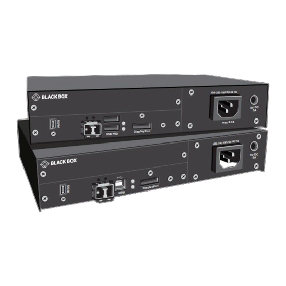
Page 25: Device Views
NEED HELP? LEAVE THE TECH TO US LIVE 24/7 CHAPTER 2: INTRODUCTION TECHNICAL SUPPORT 1.877.877.2269 2.6 DEVICE VIEWS 2.6.1 2-SLOT CHASSIS (ACXMODH2-R2/2R-R2) CPU and CON Unit Rear View 1 Slot for modules #1 2 Connect to 5-VDC power supply (standard) 3 Slot for modules #2 4 Connect to 5-VDC power supply (redundancy, optional) 2.6.2 2-SLOT CHASSIS (ACXMODH2N) -
Page 26: 4-Slot Chassis (Acxmodh4-R2/4R-R2)
NEED HELP? LEAVE THE TECH TO US LIVE 24/7 CHAPTER 2: INTRODUCTION TECHNICAL SUPPORT 1.877.877.2269 2.6.3 4-SLOT CHASSIS (ACXMODH4-R2/4R-R2) CPU and CON Unit Rear View 1 Slot for modules #3 2 Slot for modules #1 3 Connect to 5-VDC power supply (standard) 4 Slot for modules #4 5 Slot for modules #2 6 Connect to 5-VDC power supply (redundancy, optional) -
Page 27: 6-Slot Chassis Acxmodh6Bpac-R2
NEED HELP? LEAVE THE TECH TO US LIVE 24/7 CHAPTER 2: INTRODUCTION TECHNICAL SUPPORT 1.877.877.2269 NOTE: For operation with KVM Extender modules in a 6-slot chassis, two power supplies are necessary. In this case, redundancy is not applicable. NOTE: The 6-slot chassis is not equipped with a fuse on its primary side. Therefore, the protection against excessive currents has to be provided by the electrical installation of the building. -
Page 28: 6-Slot Chassis (Acxmodh6Fpac-R2)
NEED HELP? LEAVE THE TECH TO US LIVE 24/7 CHAPTER 2: INTRODUCTION TECHNICAL SUPPORT 1.877.877.2269 2.6.6 6-SLOT CHASSIS (ACXMODH6FPAC-R2) CPU and CON Unit Rear View 1 Slot for modules #5 2 Slot for modules #3 3 Slot for modules #1 4 Connect to power supply 1 5 Connect to power supply 2 (redundancy) 6 Slot for modules #6... -
Page 29: Model Acx2Mt-Dph-C/Acx2Mr-Dph-C
NEED HELP? LEAVE THE TECH TO US LIVE 24/7 CHAPTER 2: INTRODUCTION TECHNICAL SUPPORT 1.877.877.2269 Front View 1 Connect to power supply 2 2 Locking for power supply 2 (redundancy) 3 Locking for power supply 1 (standard) 4 Connect to power supply 1 2.6.8 MODEL ACX2MT-DPH-C/ACX2MR-DPH-C CPU Module CON Module... -
Page 30: Model Acx2Mt-Dph-Sm/Acx2Mr-Dph-Sm
NEED HELP? LEAVE THE TECH TO US LIVE 24/7 CHAPTER 2: INTRODUCTION TECHNICAL SUPPORT 1.877.877.2269 2.6.9 MODEL ACX2MT-DPH-SM/ACX2MR-DPH-SM CPU Module CON Module Rear View Rear View 1 Service port 1 Service port 2 Connect to interconnect cable 2 Connect to interconnect cable 3 To CPU: USB-HID 3 Connect to USB-HID devices 4 To CPU: DisplayPort... -
Page 31: Model Acx2Mt-Dph-2S/Acx2Mr-Dph-2S
NEED HELP? LEAVE THE TECH TO US LIVE 24/7 CHAPTER 2: INTRODUCTION TECHNICAL SUPPORT 1.877.877.2269 2.6.11 MODEL ACX2MT-DPH-2S/ACX2MR-DPH-2S CPU Module CON Module Rear View Rear View 1 Service port 1 Service port 2 Connect to interconnect cable 1 2 Connect to interconnect cable 1 3 Connect to interconnect cable 2 3 Connect to interconnect cable 2 4 To CPU: USB-HID... -
Page 32: Model Acx2Mr-Dp11H-2C/Acx2Mt-Dp11H-2C
NEED HELP? LEAVE THE TECH TO US LIVE 24/7 CHAPTER 2: INTRODUCTION TECHNICAL SUPPORT 1.877.877.2269 2.6.13 MODEL ACX2MR-DP11H-2C/ACX2MT-DP11H-2C CPU Module CON Module Rear View Rear View 1 Service port 1 Service port 2 Connect to interconnect cable 1 2 Connect to interconnect cable 1 3 Connect to interconnect cable 2 3 Connect to interconnect cable 2 4 To CPU: USB-HID... -
Page 33: Model Acx2Mr-Dp11H-2S/Acx2Mt-Dp11H-2S
4 Connect to USB-HID devices 5 To CPU: DisplayPort 5 Connect to DisplayPort monitor 6 To CPU: Mini DisplayPort 6 Connect to Mini DisplayPort monitor 2.6.16 MODEL ACX1MT-HID/ACX1MR-HID CPU Module CON Module Rear View Rear View 1 To CPU: USB-HID 1 Connect to USB-HID devices 1.877.877.2269... -
Page 34: Model Acx1Mt-Eu/Acx1Mr-Eu
NEED HELP? LEAVE THE TECH TO US LIVE 24/7 CHAPTER 2: INTRODUCTION TECHNICAL SUPPORT 1.877.877.2269 2.6.17 MODEL ACX1MT-EU/ACX1MR-EU CPU Module CON Module Rear View Rear View 1 To CPU: USB 2.0 1 Connect to USB 2.0 devices 2.6.18 MODEL ACX1MT-EU2/ACX1MR-EU2... -
Page 35: Model Acx1Mt-Arp/Acx1Mr-Arp
NEED HELP? LEAVE THE TECH TO US LIVE 24/7 CHAPTER 2: INTRODUCTION TECHNICAL SUPPORT 1.877.877.2269 2.6.20 MODEL ACX1MT-ARP/ACX1MR-ARP CPU Module CON Module Rear View Rear View 1 Connect to serial (D-Sub 9) 1 Connect to serial (D-Sub 9) 2 Audio IN... -
Page 36: Acx1Mt-U2-C/Acx1Mr-U2-C/Acx1Mt-U23-C/Acx1Mr-U23-C
1 Service port 1 Service port 2 Connect to interconnect cable 2 Connect to interconnect cable 3 To CPU: USB 2.0 3 Connect to USB 2.0 devices 2.6.23 MODEL ACX1MT-U2-SM/ACX1MR-U2-SM/ACX1MT-U23-SM/ACX1MR-U23-SM CPU Module CON Module Rear View Rear View 1 Service port... -
Page 37: Model Acx1Mt-U23-Sm/Acx1Mr-U23-Sm
NEED HELP? LEAVE THE TECH TO US LIVE 24/7 CHAPTER 2: INTRODUCTION TECHNICAL SUPPORT 1.877.877.2269 2.6.24 MODEL ACX1MT-U23-SM/ACX1MR-U23-SM CPU Module CON Module Rear View Rear View 1 Service port 1 Service port 2 Connect to interconnect cable 2 Connect to interconnect cable 3 To CPU: USB 2.0... -
Page 38: Status Upgrade Module Digital Audio
NEED HELP? LEAVE THE TECH TO US LIVE 24/7 CHAPTER 2: INTRODUCTION TECHNICAL SUPPORT 1.877.877.2269 LED 1 and 2: Connection Status Link 1 LED 3 and 4: Connection Status Link 2 LEDS 3 AND 4 POSITION STATUS DESCRIPTION Connection available 1, 3 Failure LED (green) On or Flashing... -
Page 39: Status Upgrade Module Usb-Hid
NEED HELP? LEAVE THE TECH TO US LIVE 24/7 CHAPTER 2: INTRODUCTION TECHNICAL SUPPORT 1.877.877.2269 LED 1: DIGITAL AUDIO STATUS LED COLOR DESCRIPTION No signal Static: CPU Unit: S/PDIF signal (RCA) available; Light Blue Flashing: CPU Unit: Digital noise Static: CPU Unit: AES/EBU signal (Mini-XLR) available; Violet Flashing: CPU Unit: Digital noise Static: CPU Unit: S/PDIF signal (TOSLINK) available;... -
Page 40: Status Upgrade Module Usb 2.0 Embedded
NEED HELP? LEAVE THE TECH TO US LIVE 24/7 CHAPTER 2: INTRODUCTION TECHNICAL SUPPORT 1.877.877.2269 2.7.4 STATUS UPGRADE MODULE USB 2.0 EMBEDDED The upgrade module USB 2.0 embedded is fitted with three further LEDs on the rear side for indication of the connection status. CPU Module CON Module Rear View... -
Page 41: Status Upgrade Module Usb 2.0 V1
NEED HELP? LEAVE THE TECH TO US LIVE 24/7 CHAPTER 2: INTRODUCTION TECHNICAL SUPPORT 1.877.877.2269 2.7.5 STATUS UPGRADE MODULE USB 2.0 V1 The upgrade module USB 2.0 is fitted with a multi color LED on both sides for overall status indication and with two further LEDs on the back side for indication of the connection status. -
Page 42: Status Upgrade Module Usb 2.0 V2
NEED HELP? LEAVE THE TECH TO US LIVE 24/7 CHAPTER 2: INTRODUCTION TECHNICAL SUPPORT 1.877.877.2269 2.7.6 STATUS UPGRADE MODULE USB 2.0 V2 The upgrade module USB 2.0 is fitted with a multi color LED on both sides for overall status indication and with two further LEDs on the back side for indication of the connection status. -
Page 43: Status Monitoring Module Snmp
NEED HELP? LEAVE THE TECH TO US LIVE 24/7 CHAPTER 2: INTRODUCTION TECHNICAL SUPPORT 1.877.877.2269 2.7.7 STATUS MONITORING MODULE SNMP The monitoring module SNMP is fitted with a multi color LED on both sides for overall status indication and with two further LEDs for indication of the network status. -
Page 44: Installation
NEED HELP? LEAVE THE TECH TO US LIVE 24/7 CHAPTER 3: INSTALLATION TECHNICAL SUPPORT 1.877.877.2269 3. INSTALLATION 3.1 PACKAGE CONTENTS Your extender package contains the following items: KVM Extender: KVM Extender pair (CPU Unit and CON Unit) in the chassis (1) (redundancy 2) 5-VDC international power supply unit per KVM Extender unit (1) (redundancy 2x) country-specific power cord DisplayPort video cable (2.0 m, DisplayPort male-to-male) - Page 45 NEED HELP? LEAVE THE TECH TO US LIVE 24/7 CHAPTER 3: INSTALLATION TECHNICAL SUPPORT 1.877.877.2269 Additional content for upgrade module Digital Audio: RCA cable (2.5 m, Cinch male connector) TOSLINK cable (1.8 m, F05 male connector) Additional content for upgrade module USB-HID: USB cable (1.8 m, USB type A to type B) Additional content for upgrade module PS/2: (2) PS/2 cables (1.8 m, 6-pole connector)
-
Page 46: System Setup
Additional content for upgrade module USB 2.0: USB cable (1.8 m, USB type A to type B) If anything is missing or damaged, contact Black Box Technical Support at 877-877-2269 or info@blackbox.com 3.2 SYSTEM SETUP We recommend that first-time users set up the system with the CPU Unit and the CON Unit in the same room as a test setup. This will allow you to identify and solve any cabling problems, and experiment with your system more conveniently. - Page 47 NEED HELP? LEAVE THE TECH TO US LIVE 24/7 CHAPTER 3: INSTALLATION TECHNICAL SUPPORT 1.877.877.2269 Upgrade Module Serial RS-422: 1. Connect the CPU to the CPU Unit by using the serial cable. 2. Connect the CON Unit to the serial connector of the input device. Upgrade Module Digital Audio: 1.
-
Page 48: Example Applications
NEED HELP? LEAVE THE TECH TO US LIVE 24/7 CHAPTER 3: INSTALLATION TECHNICAL SUPPORT 1.877.877.2269 3.3 EXAMPLE APPLICATIONS This section illustrates typical installations of KVM Extenders. KVM EXTENDER (SINGLE-HEAD) KVM EXTENDER (SINGLE-HEAD WITH DIGITAL/ANALOG AUDIO) 1.877.877.2269 BLACKBOX.COM... -
Page 49: Overview Upgrade Modules
NEED HELP? LEAVE THE TECH TO US LIVE 24/7 CHAPTER 3: INSTALLATION TECHNICAL SUPPORT 1.877.877.2269 KVM EXTENDER (DUAL-HEAD WITH 4 USB-HID) 1 Source (computer, CPU) 2 KVM Extender CPU Unit 3 Interconnect cable 4 KVM Extender CON Unit 5 Console (monitor, keyboard, mouse) 6 Second monitor (option, only with Dual-Head devices) 7 USB 2.0 devices (option, only with 2x USB 2.0 devices) 8 Audio sink (optional, only with devices with Analog Audio/Serial option or Digital Audio option) -
Page 50: Configuration
NEED HELP? LEAVE THE TECH TO US LIVE 24/7 CHAPTER 4: CONFIGURATION TECHNICAL SUPPORT 1.877.877.2269 4. CONFIGURATION 4.1 TRANSMISSION PARAMETERS The device operates with a proprietary compression method. In the default configuration, the device adapts dynamically to monitor resolution and image content. This configuration is suitable for almost all conditions and should only be modified if image quality is not fully satisfactory. -
Page 51: Usb-Hid Ghosting
NEED HELP? LEAVE THE TECH TO US LIVE 24/7 CHAPTER 4: CONFIGURATION TECHNICAL SUPPORT 1.877.877.2269 <Key> + <Key> Press keys simultaneously <Key>, <Key> Press keys successively 2x <Key> Press key quickly, twice in a row (similar to a mouse double-click) The Hotkey sequence to enter Command Mode can be changed. -
Page 52: Configuration File
NEED HELP? LEAVE THE TECH TO US LIVE 24/7 CHAPTER 4: CONFIGURATION TECHNICAL SUPPORT 1.877.877.2269 CONFIGURATION COMMANDS FOR USB-HID GHOSTING FUNCTION KEYBOARD COMMAND Writes the device descriptions of the input devices connected to the CON Unit into the CPU Unit. Activating the <Hotkey>, <h>, <w>, <Enter>... -
Page 53: Parameters For Con Units
NEED HELP? LEAVE THE TECH TO US LIVE 24/7 CHAPTER 4: CONFIGURATION TECHNICAL SUPPORT 1.877.877.2269 COMPRESSION PARAMETER FUNCTION MEDCPRATE Activate medium compression rate MINCPRATE Activate low compression rate MAXCPRATE Activate high compression rate ENADITHER Activate dithering filter for Mac OS systems SHARED OPERATION PARAMETER FUNCTION... -
Page 54: Parameters For Cpu Und Con Units
NEED HELP? LEAVE THE TECH TO US LIVE 24/7 TECHNICAL CHAPTER 4: CONFIGURATION SUPPORT 1.877.877.2269 4.5.3 PARAMETERS FOR CPU UND CON UNITS You have to write the following parameters into the configuration file of both CON Unit and CPU Unit. LOCAL SWITCHING PARAMETER FUNCTION... -
Page 55: Operation
NEED HELP? LEAVE THE TECH TO US LIVE 24/7 CHAPTER 5: OPERATION TECHNICAL SUPPORT 1.877.877.2269 5. OPERATION 5.1 DOWNLOAD OF DDC INFORMATION By default, data from the internal DDC list is reported to the source (computer, CPU). If these are not optimal settings for the display device, the DDC information of the console monitor can be downloaded and stored internally. - Page 56 NEED HELP? LEAVE THE TECH TO US LIVE 24/7 CHAPTER 5: OPERATION TECHNICAL SUPPORT 1.877.877.2269 EXAMPLE VIEW – CONFIG.TXT NOTE: When using redundant CPU Units in combination with a KVM matrix, the function of competing control will be automatically deactivated in the extender and will have to be performed by the KVM matrix. 1.877.877.2269 BLACKBOX.COM...
-
Page 57: Troubleshooting
NEED HELP? LEAVE THE TECH TO US LIVE 24/7 CHAPTER 6: TROUBLESHOOTING TECHNICAL SUPPORT 1.877.877.2269 6. TROUBLESHOOTING 6.1 GENERAL FAILURES GENERAL FAILURES DIAGNOSIS POSSIBLE REASON MEASURE Parameter not set or saved Write parameter into Config.txt file and save changes. Start Command #CFG not set Write start command #CFG into first line of the Config.txt file. -
Page 58: Usb-Hid
NEED HELP? LEAVE THE TECH TO US LIVE 24/7 CHAPTER 6: TROUBLESHOOTING TECHNICAL SUPPORT 1.877.877.2269 BLANK SCREEN TROUBLESHOOTING DIAGNOSIS POSSIBLE REASON MEASURE Check power supply units and the connection to the power LED 5, 6 off Power supply network. Connection between CON Unit and CPU LED 1, 3 on or LED 2, 4 off Check interconnect cables and connections. -
Page 59: Serial Connection
• Remove video and power cable and restart CON Unit. Connect power cable first. No USB-HID device Connect USB-HID device. USB device without function Contact Black Box Technical Support at 877-877-2269 or info@ USB-HID device is not supported blackbox.com 6.4 SERIAL CONNECTION SERIAL CONNECTION TROUBLESHOOTING... -
Page 60: Digital Audio
NEED HELP? LEAVE THE TECH TO US LIVE 24/7 CHAPTER 6: TROUBLESHOOTING TECHNICAL SUPPORT 1.877.877.2269 6.6 DIGITAL AUDIO CPU Module CON Module Rear View Rear View DIGITAL AUDIO TROUBLESHOOTING DIAGNOSIS POSSIBLE REASON MEASURE • Connect digital audio source. No audio connection to CPU/audio source •... -
Page 61: Usb 2.0 Embedded
Device at higher/lower USB-HID port not • Connect USB-HID device. LED 1/2 off detected • Contact Black Box Technical Support at 877-877-2269 or info@blackbox.com Connection between CON Unit and CPU CPU Unit: LED 3 off Check interconnect cable and connectors. -
Page 62: Usb 2.0
CON Unit: LED 3 flashing green/ light blue and USB 2.0 device • New connection of the USB 2.0 device. USB 2.0 device is not supported without function • Contact Black Box Technical Support at 877-877-2269 or info@blackbox.com 1.877.877.2269 BLACKBOX.COM... -
Page 63: Technical Support
NEED HELP? LEAVE THE TECH TO US LIVE 24/7 CHAPTER 7: TECHNICAL SUPPORT TECHNICAL SUPPORT 1.877.877.2269 7. TECHNICAL SUPPORT Before contacting support please ensure you have read this manual, and then installed and set-up your KVM Extender as recommended. 7.1 SUPPORT CHECKLIST To efficiently handle your request it is necessary that you complete a support request checklist. -
Page 64: Appendix A. Regulatory Information
NEED HELP? LEAVE THE TECH TO US LIVE 24/7 TECHNICAL APPENDIX A: REGULATORY INFORMATION SUPPORT 1.877.877.2269 APPENDIX A. REGULATORY INFORMATION A.1 CE DECLARATION OF CONFORMITY The products comply with the provisions of the following European Directives: 2014/30/EU Council Directive on the approximation of the laws of the Member States relating to electromagnetic compatibility 2014/35/EU Council Directive on the harmonization of the laws of the Member States relating to the making available on the market of electrical equipment designed for use within certain voltage limits. -
Page 65: Rohs 2
NEED HELP? LEAVE THE TECH TO US LIVE 24/7 APPENDIX A: REGULATORY INFORMATION TECHNICAL SUPPORT 1.877.877.2269 A.5 ROHS 2 This device complies with the Directive 2011/65/EU of the European Parliament and of the council of 8 June 2011 on the restriction of the use of certain hazardous substances in electrical and electronic equipment (RoHS 2, RoHS II). -
Page 66: Appendix B. Glossary
NEED HELP? LEAVE THE TECH TO US LIVE 24/7 APPENDIX B: GLOSSARY TECHNICAL SUPPORT 1.877.877.2269 APPENDIX B. GLOSSARY The following terms are commonly used in this guide or in video and KVM technology. AES/EBU: Digital audio standard that is officially known as AES3 and that is used for carrying digital audio signals between devices. CATx: Any CAT5e (CAT6, CAT7) cable CGA: Color Graphics Adapter (CGA) is an old analog graphic standard with up to 16 displayable colors and a maximum resolution of 640 x 400 pixels. - Page 67 NEED HELP? LEAVE THE TECH TO US LIVE 24/7 APPENDIX B: GLOSSARY TECHNICAL SUPPORT 1.877.877.2269 S-Video (Y/C): S-Video (Y/C) is a video format transmitting luminance and chrominance signals separately. Thereby it has a higher quality standard than CVBS. TOSLINK: Standardized fiber connection system for digital transmission of audio signals (F05 plug connection) Triple-Head: A system with three video connections USB-HID: USB-HID devices (Human Interface Device) allow for data input.
-
Page 68: Disclaimer
DISCLAIMER Black Box Corporation shall not be liable for damages of any kind, including, but not limited to, punitive, consequential or cost of cover damages, resulting from any errors in the product information or specifications set forth in this document and Black Box Corporation may revise this document at any time without notice. - Page 69 NEED HELP? LEAVE THE TECH TO US LIVE 24/7 NOTES TECHNICAL SUPPORT 1.877.877.2269 1.877.877.2269 BLACKBOX.COM...
- Page 70 NEED HELP? LEAVE THE TECH TO US LIVE 24/7 NOTES TECHNICAL SUPPORT 1.877.877.2269 1.877.877.2269 BLACKBOX.COM...
- Page 71 NEED HELP? LEAVE THE TECH TO US LIVE 24/7 NOTES TECHNICAL SUPPORT 1.877.877.2269 1.877.877.2269 BLACKBOX.COM...
- Page 72 NEED HELP? LEAVE THE TECH TO US LIVE 24/7 TECHNICAL SUPPORT 1.877.877.2269 © COPYRIGHT 2020. BLACK BOX CORPORATION. ALL RIGHTS RESERVED. ACX1MX_DP_USER_REV1.PDF...
Need help?
Do you have a question about the ACX1MR and is the answer not in the manual?
Questions and answers