Advertisement
Quick Links
Download this manual
See also:
Installation Manual
Advertisement

Related Manuals for Roger PR302


Summary of Contents for Roger PR302
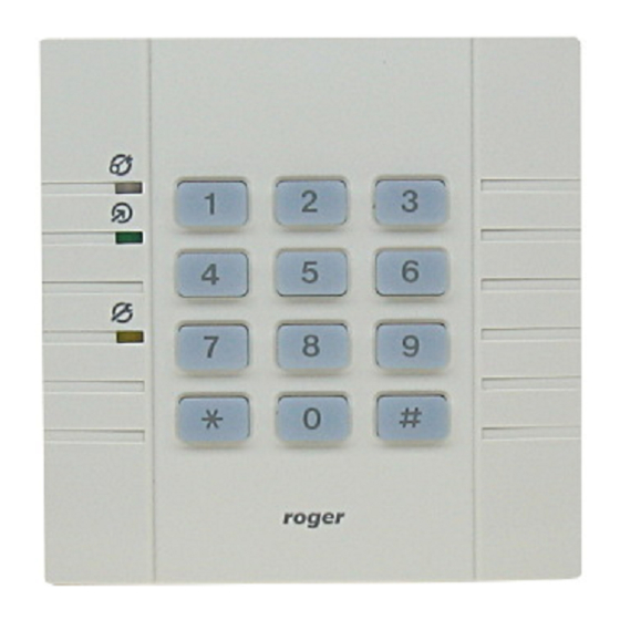
- Page 1 PR302EN.doc PR302 CCESS ONTROLLER WITH NTEGRATED & PIN R ROXIMITY EADER 119.0 IRMWARE VERSION Installation Manual...
-
Page 2: General Description
General Description The PR302 controller is dedicated for use in Access Control and Time & Attendance systems. It may be configured to perform both function simultaneously or exclusively. PR302 has a built-in proximity reader, 12 digit keypad and three LEDs. Controller offers three inputs, one relay output and two transistor outputs. - Page 3 ENTRY side of the controlled door. As a default an EXIT terminal has assigned address ID=1 where ENTRY terminal has assigned address ID=0. The PR302 and PR302LCD controllers offer one terminal build-in into theirs electronic circuit, this terminal is logically interpreted as an EXIT terminal ID=1, an ENTRY terminal ID=0 may be connected to controller’s Clock and Data lines.
- Page 4 Some brands of power supply are equipped with such a output line (e.g. PS20N from Roger). After input line is triggered controller generate [AC lost alarm ON] event, when line returns to normal condition controller generates [AC lost alarm OFF] event.
- Page 5 PR302EN.doc Selects Predefined T&A Mode – Input is dedicated to be connected to button which when pressed will turn controller to specified Momentary Type Selection T&A Mode. The T&A mode which will be set after input is triggered is declared by installer for each input line individually.
- Page 6 ON/OFF Mode of Controller PR302 controller may stay in ON or OFF mode, both modes are signalized on bi-color LED marked ON/OFF. The current mode (ON or OFF) of controller may be optionally signalized on dedicated output line (output option: Activated when controller in [ON] mode), when controller is switched from ON to OFF mode (or in reverse direction) output line will follow this changes.
- Page 7 PR302EN.doc automatically disarm adequate alarm zone. The access to premises/zone can be temporary blocked when controller stay in OFF mode, this can be achieved by option Access disabled in OFF mode. An ON/OFF mode of controller can be controlled in few listed below ways: •...
- Page 8 Operation with XM-8 module The PR302 may operate with one or two remote XM-8 I/O dedicated for lift access expanders. Both modules are connected to controller via Clock and Data lines. The first one (address ID=8) is assigned to control access to floor 1-8, where the second one (address ID=9) controls access to floors 9-16.
- Page 9 PR302EN.doc • by adequate Time Schedule (T&A Mode Schedule), • by manual command entered from controller's keypad, • by activation of input line. If option Terminals ID=0 and ID=1 have the same T&A Mode is active events registered on terminal ID=0 have the same T&A status a as events registered on terminal ID=1 (no matter if event was registered on terminal ID=1 or ID=0 they have assigned the same T&A status which is actually assigned for terminal ID=1).
-
Page 10: Installation
(<0.5m) to another reader or computer monitor, when an essential reading range reduction is observed try to relocate units. PR302 can not be mounted in external location, it hasn’t any protection against moisture, rain or cold, only indoor location are acceptable. -
Page 11: Memory Reset Procedure
Roger team constantly working on functionality enhancements so new firmware versions are released quite often (every new firmware version is published on www.roger.pl). Our customers are advised to register at web site so Roger will let inform when new versions are ready for download. - Page 12 PR302EN.doc Ordering information PR302 PR302 controller (RFID/PIN version) PR302-BK PR302 controller without keypad (RFID version only). Technical Specification 10...16 VDC (recommended linear type power supply Operating voltage range unit) Current consumption: avg. 80mA Tamper normally closed contact, 50mA rated, Reading range...
- Page 13 3. The supply voltage dropout between controller or terminal and power supply should not exceed 1.0V 4. Electric lock should be supplied from another supply source or using separate wires. 5. Controller and terminal must have the same supply minus. Typical connection diagram of PR302 access controller. PR_033UK.cdr...
- Page 14 POWER SUPPLY 12Vdc e.g. PS10/20 + 12V PR302/PR302LCD Access Controller DOOR TAMPER RS 485 IN 3 IN 2 IN 1 12 V SHLD POWER UT-2 Programming komputer PC Software RS 232 PC COMPUTER COM PORT Max 15 m Minimal connection structure for direct PR controllers programming from PC.
- Page 15 The additional relay selects gate (door) direction CLOCK DATA IO1 or IO2 output RELAY Note: The IO1(IO2) output should be configured as: “Activated when identification on terminal ID=0” Gate Control Panel Clockwise Anti clockwise TERMINAL ADDRESS ID=0 CLOCK DATA Rotary gate control via PR302/PR302LCD. cdr130EN...
- Page 16 XM-2 Installation and wiring diagram Power Supply PRxx2 Controller ( e.g. Ps20) PRTx2 Terminal AC Input TRANSFORMER Controller’s Supply Communication +ACC- Input Interface CLK DTA RESERVE 230VA BATTERY 12 V DOOR LOCK ADDRESS SELECTION REL 1 REL 2 NO-COM NC-COM The Door Lock should be wired using separate cables connected directly to power supply output IN1/IN2 ELECTRICAL...
- Page 17 R o g e r A c c e s s C o n t r o l S y s t e m T h e s t r u c t u r e o f R A C S v . 4 CPR32 Access Access...
- Page 18 R o g e r A c c e s s C o n t r o l S y s t e m An example of RACS system which incorporate 15 access controllers, CPR control panel and 3 power supplies. Note ! When system is supplied from more then one supply source, all minuses of all supplies...
- Page 19 SYSTEM 104 mm 16 mm 16 mm PR302 without keypad If PIN-codes not required keypad can be removed and replaced with plastic self-adhesive cover. The front and side view of PR302 controller and PRT32 terminal (scale 1 : 1). Cdr090EN...
- Page 20 Cdr110 Four steps to remove keypad and replace it by plastic self-adhesive front cover.
Need help?
Do you have a question about the PR302 and is the answer not in the manual?
Questions and answers