
Related Manuals for Campbell NR01


Summary of Contents for Campbell NR01
- Page 1 NR01 Four-Component Net Radiation Sensor Revision: 9/15 C o p y r i g h t © 2 0 0 8 - 2 0 1 5 C a m p b e l l S c i e n t i f i c ,...
- Page 3 Limited Warranty “Products manufactured by CSI are warranted by CSI to be free from defects in materials and workmanship under normal use and service for twelve months from the date of shipment unless otherwise specified in the corresponding product manual. (Product manuals are available for review online at www.campbellsci.com.) Products not manufactured by CSI, but that are resold by CSI, are warranted only to the limits extended by the original manufacturer.
- Page 4 SCIENTIFIC, INC., phone (435) 227-9000. After an application engineer determines the nature of the problem, an RMA number will be issued. Please write this number clearly on the outside of the shipping container. Campbell Scientific’s shipping address is: CAMPBELL SCIENTIFIC, INC.
- Page 5 • Periodically (at least yearly) check electrical ground connections. WHILE EVERY ATTEMPT IS MADE TO EMBODY THE HIGHEST DEGREE OF SAFETY IN ALL CAMPBELL SCIENTIFIC PRODUCTS, THE CUSTOMER ASSUMES ALL RISK FROM ANY INJURY RESULTING FROM IMPROPER INSTALLATION, USE, OR MAINTENANCE OF TRIPODS, TOWERS, OR ATTACHMENTS TO TRIPODS AND TOWERS SUCH AS SENSORS, CROSSARMS, ENCLOSURES, ANTENNAS, ETC.
-
Page 7: Table Of Contents
1. Introduction ..............1 2. Precautions ..............1 3. Initial Inspection ............1 4. Overview ..............2 5. Specifications ............. 3 6. Installation ..............7 NR01 Construction ................7 Mounting ....................7 Datalogger Wiring................8 6.3.1 Using a 4WPB100 ................ 9 6.3.2 Using the Datalogger’s Current Excitation Output ..... - Page 8 B. Cable Details............B-1 Figures 4-1. Atmospheric Radiation as a Function of Wavelength ......2 5-1. Dimensions of the NR01 in mm: (1) 2-Axis Leveling Assembly, (2) Mounting Arm ................3 6-1. The NR01 Four-Component Net Radiation Sensor ......7 6-2.
-
Page 9: Introduction
Care should be taken when opening the shipping package to not damage or cut the cable jacket. If damage to the cable is suspected, consult with a Campbell Scientific application engineer. Although the NR01 is rugged, it should be handled as a precision scientific • instrument. -
Page 10: Overview
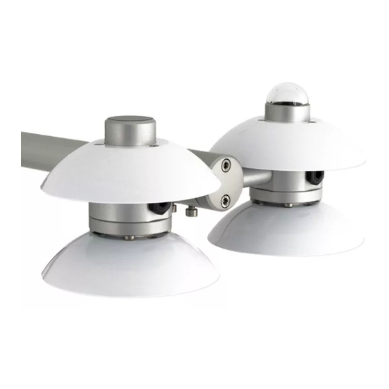
NR01 Four-Component Net Radiation Sensor Overview The NR01 is a four-component net-radiometer consisting of two pyranometers of type SR01, two pyrgeometers of type IR01, a heater, and a PT100 temperature sensor. The pyranometer measures solar radiation (short wave or SW) and the pyrgeometer measures far infrared (long wave or LW) radiation. -
Page 11: Specifications
From these also parameter like SW albedo, sky temperature, (ground) surface temperature and off course net radiation (net value of all SW and LW fluxes) can be calculated. The NR01 requires leveling; a two-axis leveling facility is incorporated in the design. See Section 6, Installation (p. 7) The NR01 is supplied with four separate instrument sensitivities. -
Page 12: General Specifications
Robust—only requiring limited maintenance • • Compatible with Campbell Scientific CRBasic dataloggers: CR6, CR1000, CR3000, CR5000, and CR9000(X). The CR1000 and CR9000(X) requires the 4WPB100 PRT Bridge Module to measure the internal RTD. -
Page 13: Pyranometer Specifications
NR01 Four-Component Net Radiation Sensor TABLE 5-2. Pyranometer Specifications Sensor Hukseflux’s thermopile pyranometer Overall classification according to Second class pyranometer ISO 9060 / WMO Response time for 95 % response 18 s Zero offset a (response to 200 < 15 W/m... -
Page 14: Pyrgeometer Specifications
NR01 Four-Component Net Radiation Sensor TABLE 5-3. Pyrgeometer Specifications Sensor IR01 pyrgeometer Overall classification Not applicable according to ISO / WMO Response time for 95 % 18 s response Window heating offset < 15 W/m (response to 1000 W/m thermal radiation) Zero offset b (response to 5 <... -
Page 15: Installation
A level is located under the radiation screens. Mounting The NR01 has a hole suitable for a 1-inch IPS pipe (33 mm diameter) for mounting the NR01 onto a CM204 or CM206 crossarm. The crossarm can be mounted to any pole with a 25-mm to 54-mm outer diameter. However, for most applications, Campbell Scientific recommends attaching the crossarm to a CM310-series pole so that the sensor is above vegetation. -
Page 16: Datalogger Wiring
Location Location of measurement should be representative of the total surrounding area, in particular in case the NR01 is used for environmental net radiation measurements. If possible, mount the sensor on a separate pole at least 25 ft away from main logger tower or tripod. -
Page 17: Using A 4Wpb100
NR01 Four-Component Net Radiation Sensor 6.3.1 Using a 4WPB100 The CR1000 and CR9000(X) require the 4WPB100 module (FIGURE 6-2) to interface the PT100 to the datalogger. Cable 1 is used to connect the pyranometer and pyrgeometer (TABLE and TABLE 6-3). Cable 2 connects the PT100 to the 4WPB100 and datalogger (TABLE 6-4). -
Page 18: Cable 1-To-Datalogger Connections When Using Single-Ended Measurements And The 4Wpb100
NR01 Four-Component Net Radiation Sensor TABLE 6-3. Cable 1-to-Datalogger Connections when using Single-Ended Measurements and the 4WPB100* Wire Label Color CR1000, CR9000(X) Pyranometer Up Sig Single-Ended Input ⏚ Pyranometer Up Ref Blue Pyranometer Down Sig White Single-Ended Input ⏚ Pyranometer Down Ref... -
Page 19: Using The Datalogger's Current Excitation Output
The sensor power can be controlled using one of the 12 V power switches built into Campbell dataloggers or using an external solid-state switch such as a PSW12/SW12. The heater current drain is approximately 140 mA from a 12 V battery. -
Page 20: Installation Of The Radiation Shields
6.6.1 Pyranometer/Pyrgeometer Measurements The NR01 outputs four voltages that typically range from 0 to 50 mV for the SR01 pyranometers, and ±5 mV for the IR01 pyrgeometer. These voltages are measured using either differential voltage measurements (VoltDiff in CRBasic) or single-ended measurements (VoltSE in CRBasic). -
Page 21: Calibration Factors
NR01 Four-Component Net Radiation Sensor 6.6.2 Calibration Factors Each NR01 is provided with a Certificate of Calibration by the manufacturer. This certificate shows the sensor serial number and sensitivity for each of the four component sensors. The individual calibration factors are unique to the... -
Page 22: Pyranometers
NR01 Four-Component Net Radiation Sensor The equation for the SW is as follows: albedo = SW / SW albedo The following equations assume the temperature is in Kelvin. NOTE Add 273.15 to equations 7-9 and 7-10 for temperature in degree Celsius. -
Page 23: Spectral Response Of The Pyranometer Compared To The Solar
7-11 pyrano, up pyrano, up In case of the NR01, the pyranometer is type SR01. This is a second-class pyranometer according to the WMO and ISO classification system (ISO 9060). The atmospheric solar radiation consists of two components—direct radiation (in a beam from the sun) and diffuse radiation from the sky. -
Page 24: Pyrgeometers
NR01 Four-Component Net Radiation Sensor 7.1.2 Pyrgeometers A pyrgeometer should measure the far infrared or LW radiation flux from a field of view of 180 degrees. The atmospheric LW radiation spectrum extends roughly from 4500 to 50000 nm. The pyrgeometer should cover that spectrum with a spectral sensitivity that is as flat as possible. -
Page 25: Main Measurement Errors In The Lw Signal
1). For example, equation 7-13 calculates, in Kelvin, the sky temperature: = (LW /5.67.10 7-13 The NR01’s pyrgeometers are type IR01. Pyrgeometers are not classified by the ISO or WMO. The atmospheric LW radiation essentially consists of two components: Low temperature radiation from the universe, filtered by the atmosphere. -
Page 26: Expected Measurement Results
NR01 Four-Component Net Radiation Sensor 7.1.3 Expected Measurement Results The average energy balance at the earth surface strongly depends on the: • Latitude (mostly for SW) • Local surface properties (SW and LW) • Local surface temperature (LW) TABLE summarizes the average global values. The average net radiation at the earth surface is positive, and the remaining energy is used for convective heat transport and evaporation. -
Page 27: Maintenance And Troubleshooting
-25 W/m Maintenance and Troubleshooting Maintenance The NR01 requires little maintenance. Dirt should be cleaned off the domes every few weeks. Usually errors in functionality appear as unreasonably large or small measured values. See TABLE for specific maintenance recommendations. -
Page 28: Troubleshooting
8.2.2 Problem Diagnosis TABLE contains information used to diagnosis problems whenever the sensor does not function properly. TABLE 8-2. Troubleshooting for the NR01 The sensor does Typically an error is due to either a short circuit or an not give any open connection. -
Page 29: Example Programs
Avg SR01 Up (short wave radiation) Avg SR01 Down (short wave radiation) Avg IR01 Up (long wave radiation) Avg IR01 Down (long wave radiation) Avg NR01 temperature (degrees C) Avg NR01 temperature (degrees K) Avg Net shortwave radiation Avg Net long wave radiation... - Page 30 Appendix A. Example Programs PT100 Temperature Sensor Connections to 4WPB100 and Datalogger Color Function 4WPB100 CR1000 Black Wire PT100 Excitation + ⏚ Blue PT100 Excitation – White PT100 Signal + Green PT100 Signal – 'CR1000 'Declare Variables and Units Public Batt_Volt Public SR01Up Public SR01Dn Public IR01Up...
- Page 31 'Default Datalogger Battery Voltage measurement Batt_Volt: Battery(Batt_Volt) 'NR01 Net Radiometer measurements SR01Up, SR01Dn, IR01Up, IR01Dn, NR01TC, NR01TK, 'NetRs, NetRl, Albedo, UpTot, DnTot, NetTot, IR01UpCo, and IR01DnCo 'For the CR1000, use autorange for the SR01 measurements due to the wide dynamic range...
-
Page 32: Cr3000 Program Using Differential Channels (No 4Wpb100
Avg SR01 Up (shortwave radiation) Avg SR01 Down (shortwave radiation) Avg IR01 Up (longwave radiation) Avg IR01 Down (longwave radiation) Avg NR01 temperature (degrees C) Avg NR01 temperature (degrees K) Avg Net shortwave radiation Avg Net longwave radiation Avg Albedo... - Page 33 'Default Datalogger Battery Voltage measurement Batt_Volt: Battery(Batt_Volt) 'NR01 Net Radiometer measurements SR01Up, SR01Dn, IR01Up, IR01Dn, NR01TC, NR01TK, 'NetRs, NetRl, Albedo, UpTot, DnTot, NetTot, IR01UpCo, and IR01DnCo 'Uses fixed ranges as they fall more in line with the range of sensor outputs, so no need to...
-
Page 34: Cr3000 Program That Controls Heater
A.3 CR3000 Program that Controls Heater This program applies power to the NR01 heater using the SW12V relay controller and the pulse width modulation instruction (PWM ()). Rather than using 0 °C as a set point for the heater, the program below uses the dewpoint value. - Page 35 '13H NR01 downwelling longwave radiation signal (brown) '13L NR01 downwelling longwave radiation signal reference (yellow) '14H NR01 upwelling longwave radiation signal (purple or pink) '14L NR01 upwelling longwave radiation signal reference (gray) 'CURRENT EXCITATION 'IX1 NR01 Pt100 current excitation (red)
- Page 36 Units panel_temp = C Units batt_volt = V Units t_hmp = C Units rh_hmp = percent Units e_hmp = kPa Units nr01 = W/m^2 Units albedo = unitless Units t_nr01 = K 'Net radiometer heater control variables. Public set_point_temperature Public duty_cycle...
- Page 37 Appendix A. Example Programs 'Find the HMP45C vapor pressure and saturation vapor pressure (kPa). VaporPressure (e_hmp,t_hmp,rh_hmp) SatVP (e_sat_hmp,t_hmp) 'Compute net radiation, albedo, downwelling and upwelling longwave radiation. t_nr01 = t_nr01/100 PRT (t_nr01,1,t_nr01,1,273.15) Rn = Rs_downwell-Rs_upwell+Rl_down_meas-Rl_up_meas albedo = Rs_upwell/Rs_downwell Rl_downwell = Rl_down_meas+(5.67e-8*t_nr01*t_nr01*t_nr01*t_nr01) Rl_upwell = Rl_up_meas+(5.67e-8*t_nr01*t_nr01*t_nr01*t_nr01) CallTable (scratch) If ( scratch.Output(1,1) ) Then...
- Page 38 Appendix A. Example Programs A-10...
-
Page 39: Cable Details
Appendix B. Cable Details TABLE provides the polarity and PCB04 connection for Cable 1 (solar), and TABLE provides the polarity and PCB04 connection for Cable 2 (PT100). TABLE shows the internal connections to the terminal blocks, which should only be required for servicing such as cable replacement. TABLE B-1. -
Page 40: Internal Electrical Diagram Of The Nr01 (For Servicing Purposes Only
Appendix B. Cable Details TABLE B-3. Internal Electrical Diagram of the NR01 (for servicing purposes only) PCB04 PCB04 PCB05 PCB05 Connection Terminal Connection Terminal Polarity Pyrgeometer – Pyrgeometer Pyrgeometer – DOWN Pyrgeometer DOWN Pyranometer Pyranometer – Pyranometer DOWN Pyranometer –... - Page 42 Santo Domingo, Heredia 40305 SOUTH AFRICA COSTA RICA • cleroux@csafrica.co.za • info@campbellsci.cc www.campbellsci.co.za www.campbellsci.cc Campbell Scientific Southeast Asia Co., Ltd. Campbell Scientific Ltd. 877/22 Nirvana@Work, Rama 9 Road Campbell Park Suan Luang Subdistrict, Suan Luang District 80 Hathern Road Bangkok 10250...
Need help?
Do you have a question about the NR01 and is the answer not in the manual?
Questions and answers