Table of Contents
Advertisement
Quick Links
Advertisement
Table of Contents

Related Manuals for Campbell SoilVUE 10


Summary of Contents for Campbell SoilVUE 10
- Page 1 Revision: 12/2020 Copyright © 2019 - 2020 Campbell Scientific CSL I.D - 1298...
- Page 3 Quotations for repairs can be given on request. It is the policy of Campbell Scientific to protect the health of its employees and provide a safe working environment, in support of this policy a “Declaration of Hazardous Material and Decontamination”...
- Page 5 About this manual Please note that this manual was originally produced by Campbell Scientific Inc. primarily for the North American market. Some spellings, weights and measures may reflect this origin. Some useful conversion factors: Area: 1 in (square inch) = 645 mm Mass: 1 oz.
- Page 7 • Periodically (at least yearly) check electrical ground connections. WHILE EVERY ATTEMPT IS MADE TO EMBODY THE HIGHEST DEGREE OF SAFETY IN ALL CAMPBELL SCIENTIFIC PRODUCTS, THE CUSTOMER ASSUMES ALL RISK FROM ANY INJURY RESULTING FROM IMPROPER INSTALLATION, USE, OR MAINTENANCE OF TRIPODS, TOWERS, OR ATTACHMENTS TO TRIPODS AND TOWERS...
-
Page 9: Table Of Contents
Table of contents 1. Introduction 2. Precautions 3. Initial Inspection 4. QuickStart 5. Overview 6. Specifications 7. Installation 7.1 Siting 7.2 Field installation 7.3 Wiring 7.4 SDI-12 programming 8. Operation 8.1 SDI-12 measurements 8.2 Measurements at fast scan rates 8.3 Measurement theory 9. -
Page 11: Introduction
Although the SoilVUE 10 is rugged, it should be handled as a precision instrument. Depth of the hole that the SoilVUE 10 is installed in needs to match the SoilVUE 10 length. Mark the installation tool to align with the length of the probe to ensure a proper depth is obtained. -
Page 12: Initial Inspection
External radio frequency (RF) sources can affect the probe operation. Therefore, the SoilVUE 10 should be located away from significant RF sources such as ac power lines and motors. 3. Initial Inspection Upon receipt of the SoilVUE 10, inspect the packaging and contents for damage. File any damage claims with the shipping company. - Page 13 3. In the Available Sensors and Devices box, type SoilVUE10 or locate the probe in the Sensors > Soil folder. Double-click SoilVUE10 Complete Soil Profiler. Type the correct SDI-12 Address; default address is 0. The Probe length defaults to 0.5 m. This is changed by clicking the Probe length box and selecting 1 m.
- Page 14 6. In Output Setup, type the scan rate, meaningful table names, and Data Output Storage Interval. CAUTION: The scan rate must be evenly divisible into fifteen minutes or one hour (depending on the Measure every selected in step 3). The 0.5 m probe can take one minute, and the 1 m probe can take one and a half minutes to complete measurements.
-
Page 15: Overview
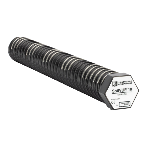
5. Overview The SoilVUE 10 uses time-domain reflectometry (TDR) to measure soil volumetric water content (VWC) and electrical conductivity (EC). The waveguides (measurement rods) are embedded in threads and centred on the measurement depths of 5, 10, 20, 30, 40, and 50 cm for the 0.5 m... -
Page 16: Specifications
The SoilVUE 10 should be installed in a hole made by a standard 5-cm (2-inch) hand auger tool. Auger the hole to the proper depth and screw the SoilVUE 10 into the hole (Field installation 8)). Water should be used to lubricate the sides of the hole to aid in installation and to ensure the probe is not damaged due to excessive force. -
Page 17: Installation
For more information on installation, watch a video at www.campbellsci.eu/videos/soilvue10 Proper installation of the SoilVUE 10 is critical. This includes selecting a monitoring site that is representative of the soil of interest, ensuring good contact between the waveguides and the... -
Page 18: Field Installation
The installation kit is not necessary to install the SoilVUE 10. A standard 5 cm (2-inch) hand auger may be used instead of the auger supplied in the kit. The SoilVUE 10 can then be inserted into the hole using a standard six-sided 2.25-inch socket. - Page 19 2. Use the auger assembly to create a hole with a 5 cm (2 inch) diameter that is approximately 5 cm (2 inch) deeper than the SoilVUE 10 length. The auger is narrow at the tip, so making the hole 5 cm (2 inch) deeper will ensure the sensor can be fully installed.
- Page 20 3. Insert the hex socket handle into the small holes in the hex socket (FIGURE 7-2 (p. 10)). FIGURE 7-2. Hex socket handle and hex socket CAUTION: Leave the plastic cap on the cable connection until the sensor is completely installed and ready to connect the cable.
-
Page 21: Wiring
When the top of the probe is flush with the soil surface, the top sensor is at 5 cm (2 inch) depth. 5. Connect the cable to the SoilVUE 10, and hand tighten the cable connector nut to ensure a water-tight seal. Do not over tighten. The cable nut should turn easily. If it does not, check to make sure it is correctly aligned. -
Page 22: Operation
Table 8-1 (p. 13). Because of the delays the M! command requires, Campbell Scientific recommends measurement scans of at least 10 seconds per sensor. For instance, the recommended scan rate for a 0.5 m probe with six sensors is at least 60 seconds. A C! command does not require the data logger to pause its operation until the values are ready. - Page 23 Table 8-1: SoilVUE 10 SDI-12 commands SDI-12 command Values returned or function Units (a is the SDI-12 address) 1. Volumetric Water Content, 5 cm 2. Volumetric Water Content, 10 cm 3. Volumetric Water Content, 20 cm 4. Volumetric Water Content, 30 cm 5.
- Page 24 Table 8-1: SoilVUE 10 SDI-12 commands SDI-12 command Values returned or function Units (a is the SDI-12 address) 1. Volumetric Water Content, 50 cm 2. Relative Permittivity, ɛ, 50 cm aM6! or aC6! 3. Temperature, 50 cm °C 4. Bulk Electrical Conductivity, 50 cm dS/m 1.
- Page 25 Table 8-1: SoilVUE 10 SDI-12 commands SDI-12 command Values returned or function Units (a is the SDI-12 address) 15. Temperature, 30 cm °C 16. Bulk Electrical Conductivity, 30 cm dS/m 17. Volumetric Water Content, 40 cm 18. Relative Permittivity, ɛ, 40 cm 19.
-
Page 26: Measurements At Fast Scan Rates
8.3 Measurement theory The SoilVUE 10 is a multiparameter soil profile probe that measures soil volumetric water content using a time-domain reflectometry (TDR) method. The probe consists of TDR circuitry connected to a series of six or nine helical waveguides that makeup part of the overall threaded design. -
Page 27: Maintenance And Troubleshooting
“Statement of Product Cleanliness and Decontamination” form. Refer to Assistance page at the end of this manual for more information. The SoilVUE 10 does not require periodic maintenance. For troubleshooting, Table 9-1 (p. 17) provides symptoms, possible causes, and solutions. -
Page 29: Appendix A. Importing Short Cut Code Into Crbasic Editor
Appendix A. Importing Short Cut code into CRBasic Editor Short Cut creates a .DEF file that contains wiring information and a program file that can be imported into the CRBasic Editor. By default, these files reside in the C:\campbellsci\SCWin folder. Import Short Cut program file and wiring information into CRBasic Editor: 1. -
Page 31: Appendix B. Sdi-12 Sensor Support
SDI-12, Serial Data Interface at 1200 baud, is a protocol developed to simplify sensor and data logger compatibility. Only three wires are necessary — serial data, ground, and 12 V. With unique addresses, multiple SDI-12 sensors can connect to a single SDI-12 terminal on a Campbell Scientific data logger. -
Page 32: Acknowledge Active Command (A!)
Table B-1: Campbell Scientific sensor SDI-12 command and response set Response Name Command aAb! Change Address b<CR><LF> Start Measurement atttn<CR><LF> aM1!...aM9! aMC! Start Measurement atttn <CR><LF> aMC1!...aMC9! and Request CRC Start Concurrent Measurement atttnn<CR><LF> aC1!...aC9! aCC! Start Concurrent Measurement atttnn<CR><LF> aCC1!...aCC9! and Request CRC a<values><CR><LF>... -
Page 33: Start Verification Command (Av!)
cccccccc 8-character vendor identification mmmmmm 6 characters specifying the sensor model 3 characters specifying the sensor version (operating system) Up to 13 optional characters used for a serial number or other specific xxx…xx sensor information that is not relevant for operation of the data logger Terminates the response <CR><LF>... -
Page 34: Start Measurement Commands (Am!)
B.7 Start measurement commands (aM!) A measurement is initiated with the M! command. The response to each command has the form atttn<CR><LF>, where a = sensor address ttt = time, in seconds, until measurement data is available. When the data is ready, the sensor notifies the data logger, and the data logger begins issuing D commands. -
Page 35: Sdi-12 Transparent Mode
Transparent mode is entered while the computer is communicating with the data logger through a terminal emulator program. It is accessed through Campbell Scientific data logger support software or other terminal emulator programs. Data logger keyboards and displays cannot be used. -
Page 36: Changing An Sdi-12 Address
SDI-12 sensor. The steps shown in Changing an SDI-12 address (p. 24) are used with most Campbell Scientific data loggers. B.10.1 Changing an SDI-12 address This example was done with a CR1000X, but the steps are only slightly different for CR6, CR3000, CR800-series, CR300-series, CR1000 data loggers. - Page 37 9. To query the sensor for its current SDI-12 address, type ?! and press Enter. The sensor responds with its SDI-12 address. If no characters are typed within 60 seconds, the mode is exited. In that case, simply type SDI12 again, press Enter, and type the correct control port number when prompted.
- Page 38 Campbell Scientific regional offices Australia France Thailand Location: Garbutt, QLD Australia Location: Vincennes, France Location: Bangkok, Thailand Phone: 61.7.4401.7700 Phone: 0033.0.1.56.45.15.20 Phone: 66.2.719.3399 Email: info@campbellsci.com.au Email: info@campbellsci.fr Email: info@campbellsci.asia Website: www.campbellsci.com.au Website: www.campbellsci.fr Website: www.campbellsci.asia Brazil Germany Location: São Paulo, SP Brazil...
Need help?
Do you have a question about the SoilVUE 10 and is the answer not in the manual?
Questions and answers