
Subscribe to Our Youtube Channel
Related Manuals for Campbell DustVue


Summary of Contents for Campbell DustVue
- Page 1 PRODUCT MANUAL DustVue In-Field Soiling Measurement for Operational and Site Assessment (IEC 61724-1 Compliant) Revision: 08/2023 2023 Copyright © Campbell Scientific, Inc.
-
Page 2: Table Of Contents
Table of contents 1. Introduction 2. Precautions 3. Initial inspection 4. QuickStart 4.1 Configuration 4.2 User entered values 4.2.1 Definitions of UserEntered and solar panel 4.3 View data 4.4 Modbus settings and data 5. Overview 6. Specifications 6.1 Back-of-module temperature measurements 6.2 Modbus TCP communications 6.3 System 6.4 Power requirements... -
Page 3: Introduction
The DustVue is designed to be the principle component of an independent soiling measurement station, or as an add-on peripheral to any new or existing meteorological station. The DustVue is delivered field ready and requires no programming. The DustVue will work with any photovoltaic (PV) panel up to 700 W. -
Page 4: Initial Inspection
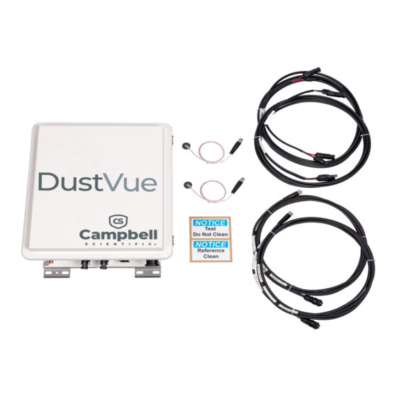
CR310 Certificate of Calibration 8 GB USB flash drive with Device Configuration Utility software Upon receipt of the DustVue, inspect the packaging and contents for damage. File damage claims with the shipping company. Immediately check package contents. Thoroughly check all packaging material for product components that may be concealed. - Page 5 5. Set time. Although set at the factory, confirm time settings are correct and if necessary, reset the clock at the time of deployment. a. In the Logger Control tab use the drop down next to Reference Clock Setting and select UTC (Greenwich Mean Time). Click Set Clock to apply the setting. DustVue...
-
Page 6: User Entered Values
4.2 User entered values UserEntered values will be applied at the factory prior to shipping if they are provided to Campbell Scientific when the DustVue is ordered. Confirm all UserEntered values are entered correctly at the time of deployment. CAUTION: Be sure to check the Longitude_UserEntered, TempCoefflscTest_UserEntered, TempCoefflscRef_ UserEntered, IscTeststc_UserEntered, and IscRefstc_UserEntered values. -
Page 7: Definitions Of Userentered And Solar Panel
Default = 500 W/m User editable field that defines the minimum number of stable data counts for (re)calculating soiling index. Also the Stable_Data_Count_UserEntered minimum number of stable data counts for performing an offset correction. Default = 20 DustVue... -
Page 8: View Data
Enter a value of 1 to save user entered/edited values and ApplyAndRestart restart the DustVue 4.3 View data The DustVue outputs data over Modbus TCP (see Modbus register map (p. 17). Live data is shown in the Public table. To verify the system is working as expected, review the Raw_Measurement_ Data and the Modbus_Register_Map values. -
Page 9: Modbus Settings And Data
4.4 Modbus settings and data The following table shows default Modbus settings for the DustVue. Any device querying information from the DustVue must have the same settings in order to receive the information. Table 4-2: Modbus configuration Parameter... -
Page 10: Overview
5. Overview The DustVue uses the comparison-of-short-circuit method for assessing solar module performance and losses due to soiling. Numerous studies have compared the advantages and disadvantages of the different methods used to calculate losses due to soiling. These studies DustVue... -
Page 11: Specifications
The DustVue can be directly integrated with on-site SCADA using Modbus TCP or it can be added to new or existing solar meteorological monitoring systems (bottom of Figure 5-1 [p. -
Page 12: Modbus Tcp Communications
Typical power requirements: Sleep: 1.5 mA Active 1 Hz scan with analog measurement: 5 mA USB power (USB): For programming and limited functionality 6.5 Compliance IEC 61724-1 (2021) compliant. View compliance documents at www.campbellsci.com/dustvue. DustVue... -
Page 13: Maintenance Button
Figure 7-1 (p. 11) shows the connector panel. WARNING: To prevent injury, completely cover the PV panels to limit output and current and voltage during installation. Do not short PV panel + and – wires. Figure 7-1. DustVue connector panel DustVue... -
Page 14: Operation
Descriptions of available values are shown in Variable description (p. 15) In accordance with IEC 61724-1 (2021), the DustVue calculates the daily soiling loss index during the hour before and the hour after solar noon. Only the values showing effective irradiance greater than 500 W/m are included to minimize the effects from the zenith angle of the sun, PV panel current dependence on irradiance level, and air mass density. -
Page 15: Offset Correction
3. Results will be available when the minimum number of data points has been met for calculating a good offset value. This is typically midnight if the offset was initiated in the morning, or midnight of the following day if the offset was initiated in the afternoon or evening. DustVue... -
Page 16: Maintenance
If the maintenance button is inadvertently pressed for more than 5 s and the offset correction is not needed, the process can be aborted by accessing the DustVue through the assigned IP address and using Device Configuration Utility to reset the Offset Correction variable to 0 before midnight. -
Page 17: Appendix A. Variable Description
Appendix A. Variable description Table A-1: Glossary of variable names Variable name Description RTU_Internal_Temp Panel temperature of DustVue, °C RTU_Voltage Battery voltage of DustVue, VDC Soiling_Loss_Index_Corrected Soiling loss index with offset correction applied, % Soiling_Loss_Index_Raw Soiling loss index without offset correction applied, %... - Page 18 %/°C, then enter published value/100) Published panel short-circuit current (Isc) of the test panel at IscTeststc_UserEntered Published panel short-circuit current (Isc) of the reference IscRefstc_UserEntered panel at STC Solar noon of site location, as determined by user-entered LocalSolarNoon site location data DustVue...
-
Page 19: Appendix B. Modbus Register Map
ModbusData(13) 40025 40026 reference module) ModbusData(14) Update_Offset (offset update triggered) 40027 40028 –1 User_Entered_UTC_Offset (hour offset ModbusData(15) 40029 40030 –12 from UTC time) ModbusData(16) User_Entered_Latitude 40031 40032 Degrees ModbusData(17) User_Entered_Longitude 40033 40034 Degrees ModbusData(18) User_Entered_Test_Temperature_Coeff 40035 40036 No Max DustVue... - Page 20 40047 40048 Volts ModbusData(25) RTU_Internal_Temperature 40048 40050 –40 °C ModbusData(26) LocalSolarNoon 40051 40052 12:00 13:00 ModbusData(27) CleanPanelWashed_Year 40053 40054 ModbusData(28) CleanPanelWashed_Month 40055 40056 ModbusData(29) CleanPanelWashed_Day 40057 40057 ModbusData(30) DirtyAndCleanWashed_Year 40059 40060 ModbusData(31) DirtyAndCleanWashed_Month 40061 40062 ModbusData(32) DirtyAndCleanWashed_Day 40063 40064 DustVue...
- Page 21 See Product Details on the Ordering Information pages at www.campbellsci.com . Other manufacturer's products, that are resold by Campbell Scientific, are warranted only to the limits extended by the original manufacturer. Refer to www.campbellsci.com/terms#warranty for more information.
- Page 22 To obtain a Returned Materials Authorization or Repair Reference number, contact your CAMPBELL SCIENTIFIC regional office. Please write the issued number clearly on the outside of the shipping container and ship as directed. For all returns, the customer must provide a “Statement of Product Cleanliness and Decontamination”...
- Page 23 Comply with all electrical codes. Electrical equipment and related grounding devices should be installed by a licensed and qualified electrician. Only use power sources approved for use in the country of installation to power Campbell Scientific devices. Elevated Work and Weather Exercise extreme caution when performing elevated work.
- Page 24 Periodically (at least yearly) check electrical ground connections. WHILE EVERY ATTEMPT IS MADE TO EMBODY THE HIGHEST DEGREE OF SAFETY IN ALL CAMPBELL SCIENTIFIC PRODUCTS, THE CUSTOMER ASSUMES ALL RISK FROM ANY INJURY RESULTING FROM IMPROPER INSTALLATION, USE, OR MAINTENANCE OF TRIPODS, TOWERS, OR ATTACHMENTS TO TRIPODS...
- Page 25 Campbell Scientific Regional Offices Australia France Thailand Location: Garbutt, QLD Australia Location: Montrouge, France Location: Bangkok, Thailand Phone: 61.7.4401.7700 Phone: 0033.0.1.56.45.15.20 Phone: 66.2.719.3399 Email: info@campbellsci.com.au Email: info@campbellsci.fr Email: info@campbellsci.asia Website: www.campbellsci.com.au Website: www.campbellsci.fr Website: www.campbellsci.asia Brazil Germany Location: São Paulo, SP Brazil...
Need help?
Do you have a question about the DustVue and is the answer not in the manual?
Questions and answers