
Related Manuals for ICOP Technology IBW-35


Summary of Contents for ICOP Technology IBW-35
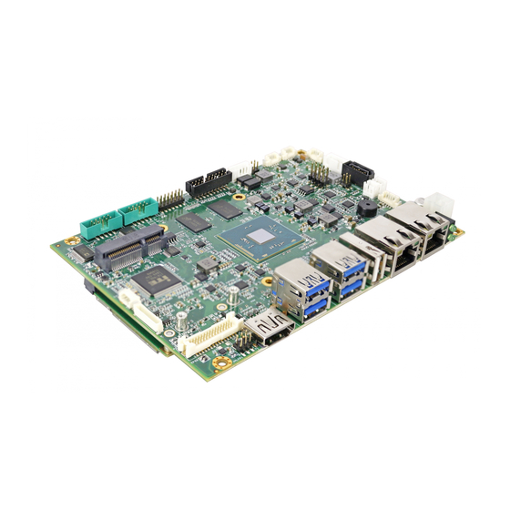
- Page 1 User Manual IBW-35 A 3.5” embedded solution on ® Intel Quad-core Processor (Braswell Family) Version 1.0 ICOP Technology Inc.
- Page 2 No part of this manual may be reproduced, copied, translated or transmitted, in whole or in part, in any form or by any means without the prior to written permission of ICOP Technology Inc.
- Page 3 IBW35 User Manual Revision History Revision Date Remark February 25, 2020 First version release ICOP Technology Inc.
-
Page 4: Table Of Contents
1.1 Overview ............................1 1.2 Block diagram ..........................1 1.3 Specifications ..........................2 1.4 Ordering Information ........................4 1.4.1 IBW-35 ............................ 4 1.4.2 Option Accessary ........................4 Hardware Information ..................5 2.1 Dimension ............................. 5 2.2 Board Outline ..........................6 2.3 Connector and Jumper Summary .................... - Page 5 JINV1: Power Selection for INV1 ....................16 JVLCD1: Power Selection for LCD Panel ..................17 LVDS1: LVDS ..........................17 INV1: LCD Backlight Control ....................... 18 Technical Support Directly from ICOP ..............15 User Manual Feedback ..................... 15 Warranty ........................16 ICOP Technology Inc.
-
Page 6: General Information
IBW35 supports 2x Gigabit LAN, 4x COM, 6x USB, I C, 16-bit GPIO, MiniPCIe, HDMI, LVDS, VGA, and 3 storage options, storage as SATA interface, mSATA interface, and Micro SD for development use. SIM card holder is also supported on IBW-35 for wireless long-distance communication. 1.2 Block diagram... -
Page 7: Specifications
Realtek ALC262 VD Micro SD x1 Disk Support SATA device x1 mSATA device COM x4 C x1 I/O Interface USB3.0 x4 USB2.0 x2 16-bit GPIO x1 *mSATA interface could be configured as a standard MiniPCIe interface through H/W modification ICOP Technology Inc. - Page 8 SIM card holder x1 Power 12V standard input from internal 4-pin power connector support for ATX mode Requirement Operating Temp. 0°C to +60°C Dimensions 102mm x 146mm Weight 120g Windows 10 O/S Support Windows 7 (64bits) Linux ICOP Technology Inc.
-
Page 9: Ordering Information
N3160) System Memory 4GB DDR3L 1600MHz Accessary CABLE-SATA-IBW-15CM x1 1.4.2 Optional Accessary CABLE-SET-IBW35 Cable set for IBW-35 (RS232 x4, GPIO x1, Audio x3) CABLE-ATX12V-10CM ATX12V 2x2 Pin to DC power jack cable CABLE-VGA-IBW35-15CM VGA cable for IBW-35 ICOP Technology Inc. -
Page 10: Hardware Information
IBW35 User Manual 2 Hardware Information 2.1 Dimension ICOP Technology Inc. -
Page 11: Board Outline
IBW35 User Manual 2.2 Board Outline TOP: BOTTOM: ICOP Technology Inc. -
Page 12: Connector And Jumper Summary
Box Header, 2.0mm, 10x2 USB(2.0) 1 Wafer, 1.25mm, 5x1 USB(2.0) 2 Type A USB2.0 Connector Power Input Wafer, 4.2mm, 2x2 JINV1 Power Selection for INV1 Pin Header, 2.0m, 2x2 JVLCD1 Power Selection for LCD Panel Pin Header, 2.0mm, 2x3 ICOP Technology Inc. - Page 13 IBW35 User Manual LVDS1 LVDS Wafer, 1.25mm, 15x2 INV1 LCD Backlight Control Wafer, 2.0mm, 5x1 LED2 Wireless LED LED-SMD LED3 SATA DOM LED LED-SMD ICOP Technology Inc.
-
Page 14: Pin Assignments & Jumper Settings
2.4 Pin Assignments & Jumper Settings J2: LPC Header Pin# Signal Name Pin# Signal Name LPC_CLKOUT L_FRAME_N VCC5 PLTRST_3P3_N LPC_AD3 LPC_AD2 VCC3 LPC_AD1 LCD_ADD LCD_SMB_CLK LPC_SMB_DAT J8: VGA Pin# Signal Name ROUT GOUT BOUT VGADDCSDA HSYNC_A VSYNC_A VGADDCCLK ICOP Technology Inc. -
Page 15: J10: Jumper Selection For At/Atx
J10: Jumper Selection for AT/ATX Pin 1&2 closed AT mode ATX mode Pin 1&2 open J11: Power for SATA HDD Pin# Signal Name VCC12 VCC5 J12: SATA DOM Pin# Signal Name SATA_TXP SATA_TXN SATA_RXN SATA_RXP ICOP Technology Inc. -
Page 16: J14: Sim Card Holder
IBW35 User Manual J14: SIM Card Holder Pin# Signal Name SIM-VCC SIM-RST SIM-CLK SIM-VPP SIM-IO J15: Line-in Pin# Signal Name LINE_IN_R LINE_IN_L J15: Line-out Pin# Signal Name LOUT_R LOUT_L ICOP Technology Inc. -
Page 17: J17: Mic-In
IBW35 User Manual J17: MIC-in Pin# Signal Name MIC_IN_R MIC_IN _L J18: I Pin# Signal Name I2C5_SDA_3P3 I2C5_SCL_3P3 VCC3 J23: Power Button Pin# Signal Name PWRBTN ICOP Technology Inc. -
Page 18: J24: Reset Button
IBW35 User Manual J24: Reset Button Pin# Signal Name RSTBTN J25: COM1 (RS232) Pin# Signal Name Pin# Signal Name DCD1 RXD1 TXD1 DTR1 DSR1 RTS1 CTS1 VCC5 ICOP Technology Inc. -
Page 19: J26: Com2 (Rs232)
User Manual J26: COM2 (RS232) Pin# Signal Name Pin# Signal Name DCD2 RXD2 TXD2 DTR2 DSR2 RTS2 CTS2 VCC5 J27: COM3 (RS232/422/485) Pin# Signal Name Pin# Signal Name DCD3/422TX-3 RXD3/422TX+3 /1RS485-3 /1RS485+3 TXD3/422RX+3 DTR3/422RX-3 DSR3 RTS3 CTS3 VCC5 ICOP Technology Inc. -
Page 20: J28: Com4 (Rs232/422/485)
DCD4/422TX-4 RXD4/422TX+4 /2RS485-4 /2RS485+4 TXD4/422RX+4 DTR4/422RX-4 DSR4 RTS4 CTS4 VCC5 J29: GPIO Pin# Signal Name Pin# Signal Name VCC5 GP80 GP70 GP81 GP71 GP82 GP72 GP83 GP73 GP84 GP74 GP85 GP75 GP86 GP76 GP87 GP77 VCC5 P_PERROR- ICOP Technology Inc. -
Page 21: J30: Usb(2.0) 1
J32: USB(2.0) 1 Pin# Signal Name VCC5 USB- USB+ J32: Power Input Pin# Signal Name Pin# Signal Name +12V +12V JINV1: Power Selection for INV1 Pin 1&2 closed +5VDC input support Pin 3&4 closed +12VDC input support ICOP Technology Inc. -
Page 22: Jvlcd1: Power Selection For Lcd Panel
Pin 5&6 closed +12VDC input support LVDS1: LVDS Pin# Signal Name Pin# Signal Name LVDS_A0+ LVDS_A0- LVDS_A1- LVDS_A2+ LVDS_A2+ LVDS_A2- LVDS_ACLK- LVDS_ACLK+ LVDS_A3- LVDS_A3+ LVDS_B0+ LVDS_B0- LVDS_B1- LVDS_B1+ LVDS_B2+ LVDS_B2- LVDS_B3+ LVDS_B3- DDC_SDA DDC_CLK LVDS_BCLK+ LVDS_BCLK- ICOP Technology Inc. -
Page 23: Inv1: Lcd Backlight Control
IBW35 User Manual INV1: LCD Backlight Control Pin# Signal Name INV_LVDS L_BKLT_EN LCD_BKLT_CTRL ICOP Technology Inc. -
Page 24: Technical Support Directly From Icop
—Any complement or technical situations you want ICOP more focusing on User Manual Feedback To make this user manual more complete, if you have any comments or feedbacks to this manual, please feel free to write to info@icop.com.tw or contact your ICOP sales representative. ICOP Technology Inc. -
Page 25: Warranty
Merchandise Authorization (RMA) number. Returned goods should always be accompanied by a clear problem description. Should you have questions about warranty and RMA service, please contact us directly. ICOP Technology Inc. Address: No. 15 Wugong 5th Road, Xinzhuang Dist. New Taipei City, Taiwan (R.O.C.) 24890...
Need help?
Do you have a question about the IBW-35 and is the answer not in the manual?
Questions and answers