
Subscribe to Our Youtube Channel
Related Manuals for Belden Grass Valley KMX-3921


Summary of Contents for Belden Grass Valley KMX-3921
- Page 1 KMX-3921 SCALABLE KALEIDO MULTIVIEWER FOR DENSITÉ 3+ Installation & Service Manual M3033-9903 AB 2018-05-30...
- Page 2 Copyright & Trademark Notice Copyright © 2018, Grass Valley Canada. All rights reserved. Belden, Belden Sending All The Right Signals, and the Belden logo are trademarks or registered trademarks of Belden Inc. or its affiliated companies in the United States and other jurisdictions.
- Page 3 KMX-3921 Installation & Service Manual Electrostatic Discharge (ESD) Protection Electrostatic discharge occurs when electronic components are improperly handled and can result in intermittent failure or complete damage adversely affecting an electrical circuit. When you remove and replace any card from a frame always follow ESD-prevention procedures: •...
- Page 4 Notices Certification and Compliance Safety of Laser Modules This equipment may incorporate modules containing Class 1 lasers. These modules are certified by the manufacturer to comply with: – IEC/EN 60825-1:2014 Safety of laser products Electromagnetic Compatibility This equipment has been tested for verification of compliance with FCC Code of Federal Regulations, Title 47, Part 15 (47 CFR 15), Subpart B, Class A, Digital Devices, Unintentional Radiators.
- Page 5 KMX-3921 Installation & Service Manual Environmental Compliance 有毒有害物质或元素 (Toxic or hazardous substances and elements) 铅 汞 镉 六价铬 多溴联苯 多溴二苯 部件名称 Part name (Pb) (Hg) (Cd) (Cr6) (PBB) (PBDE) 电缆及电缆组件 Cables and cable assemblies 电路模块 Circuit modules 组装风扇 Fan assemblies O: 表示该有毒有害物质在该部件所有均质材料中的含量均在...
- Page 6 Notices...
-
Page 7: Table Of Contents
Table of Contents Table of Contents 1 Overview ............11 Related Documentation . - Page 8 Table of Contents Multiviewer SFP Module Mosaic Output to a 4K Display Input Cable Connections....45 Landscape Multiviewer Display Orientation ........... . 46 Portrait Multiviewer Display Orientation.
- Page 9 KMX-3921 Installation & Service Manual XAdmin Access Control ................91 Enabling XAdmin Access Control .
- Page 10 Table of Contents Maintenance ..................127 Required Tools .
-
Page 11: Overview
Overview Welcome to the Kaleido family of multiviewers! This Installation & Service Manual is designed to help you get your KMX-3921 multiviewer up and running. The following chapters will guide you through the installation of a KMX-3921 system in its default configuration. -
Page 12: Introduction
Overview Introduction Introduction The KMX-3921 multiviewer can be installed in either a Densité 3+ FR1 frame or a Densité 3+ FR4 frame. The KMX-3921 cards are installed in the frame with a corresponding back panel that is installed at the rear of the frame. Each KMX-3921 card can display up to nine SD, HD, or 3G-SDI video sources in up to nine video windows across one or two high- resolution mosaic outputs. -
Page 13: Supported Frames And Multiviewer Scaling
KMX-3921 Installation & Service Manual KMX-3921 features (continued) Feature Description Seamless Kaleido multiviewers can be mixed and matched to create a seamless control across monitoring system across a facility. multiple Choice of control options such as the standalone Kaleido-RCP2 or RCP-200 multiviewers panels, integrated with router control systems and panels, iControl, and third-party control systems. -
Page 14: Current Limitations
Overview Current Limitations Frame Available Controller Supported Frame Slots Model Multiviewer Scaling (continued) Densité 3+ FR4 CPU-ETH3 Combine up to six KMX-3921 cards, to configure a -STD dual- or quad-mosaic output system in the standard following sizes: frame 1 card: 9 × 1 and 9 × 2 controller 2 cards: 18 ×... -
Page 15: Kmx-3921 Multiviewer Cards
KMX-3921 Installation & Service Manual KMX-3921 Multiviewer Cards The KMX-3921 is available in a number of models shown in the table below. KMX-3921 module selection Description Densité 3+ KMX-3921-9X1 9x1 Kaleido multiviewer card for (SD/HD/3G SDI). KMX-3921-9X2 9x2 Kaleido multiviewer card for Densité... -
Page 16: Kmx-3921 Rear Panels
Overview KMX-3921 Rear Panels KMX-3921 Rear Panels The KMX-3921 rear panels provide SFP slots for optional rear panel connection for up to four displays. Rear panels that support between two and six cards also serve to interconnect the KMX-3921 cards. These rear panels are available in a number of models shown in the table below. -
Page 17: Multiviewer Scaling
KMX-3921 Installation & Service Manual KMX-3921-54X4-3+HR Multiviewer Scaling The multiviewer is scaled by selecting an appropriate KMX-3921 rear panel model for your solution with the corresponding number of KMX-3921 cards to be used with that rear panel as shown below. KMX-3921-9X2-3+SR Rear Panel This configuration can be installed either in a Densité... - Page 18 Overview Multiviewer Scaling Controller Model, on page 22. Multiviewer Capacity Required Multiviewer Cards SFP Module Requirements 18 × 1 2 × KMX-3921-9X1 One single Tx SFP module is required to support this capacity when displays are directly connected to the multiviewer’s rear panel.
- Page 19 KMX-3921 Installation & Service Manual Controller Model, on page 22. Multiviewer Capacity Required Multiviewer Cards SFP Module Requirements 36 × 1 4 × KMX-3921-9X1 One single Tx SFP module is required to support this capacity when displays are directly connected to the multiviewer’s rear panel.
-
Page 20: Compatible Sfp Modules
Overview Compatible SFP Modules Compatible SFP Modules To connect display(s) to the multiviewer’s rear panel mosaic output, the appropriate SFP module(s) must be ordered. SFP module selection Description SFP-3G-2OUT-L Dual output HD/3G SDI long-reach coaxial SFP with DIN 1.0/2.3 connectors. SFP-HDMI-OUT Single output HDMI type D SFP with retention lock, cable not included (see below). -
Page 21: Multiviewer Sdi / Madi Input Combinations
KMX-3921 Installation & Service Manual Multiviewer SDI / MADI Input Combinations Certain multiviewer inputs can accept a MADI signal instead of an SDI input as detailed in the table below. For input specifications, see Video Inputs, on page 143 and Discrete Audio Inputs, on page 145. -
Page 22: How To Identify A Densité 3+ Fr4 Frame's Controller Model
Overview How to Identify a Densité 3+ FR4 Frame’s Controller Model How to Identify a Densité 3+ FR4 Frame’s Controller Model All Densité 3+ FR4 frames are equipped with a CPU-ETH3 frame controller. However, there are a number of different available CPU-ETH3 frame controller models that may limit the multiviewer capacity supported by the frame. - Page 23 KMX-3921 Installation & Service Manual 2 Navigate to Controller Information found under Status. 3 Identify the frame’s controller model found after Card Model. Card Model Description Corresponding Rear Panel basic The frame is currently equipped with a Densité CPU-ETH3-RP CPU-ETH3 basic frame controller. This Densité...
- Page 24 Overview How to Identify a Densité 3+ FR4 Frame’s Controller Model To find the frame’s controller model by visual inspection If the frame is unpowered, another way to know if your Densité 3+ FR4 frame is equipped with a CPU-ETH3-ADV advanced frame controller is to visually inspect the rear of the Densité...
-
Page 25: Kaleido Software Minimum Version Compatibility
KMX-3921 Installation & Service Manual Kaleido Software Minimum Version Compatibility A KMX-3921 multiviewer cannot be downgraded to a Kaleido Software version earlier than 10.00. When downgrading this multiviewer, certain other requirements and limitations may be in effect; see Upgrading the Multiviewer, on page 136 for more information. -
Page 26: Overview Of The Kmx-3921 System
Overview Overview of the KMX-3921 System Overview of the KMX-3921 System Between one to six KMX-3921 cards are interconnected through the rear panel according to your application’s sizing as shown below. Multiviewer Inputs Multiviewer Outputs KMX-3921 9 Inputs 1 Cards KMX-3921 18 Inputs 2 Cards... -
Page 27: Installation
Installation This chapter provides information about system requirements, items shipped with your KMX-3921 multiviewer and it will guide you through the installation of a KMX-3921 multiviewer. Getting Organized / Unpacking Make sure the following items have been shipped with your KMX-3921 order. If any of these are missing, contact your distributor or Grass Valley (see Grass Valley Technical Support, on... -
Page 28: Densité 3+ Fr1 Frame Physical Interface
Installation Densité 3+ FR1 Frame Physical Interface Densité 3+ FR1 Frame Physical Interface A single KMX-3921 card is installed in the Densité 3+ FR1 frame. When the frame door is closed, the status LEDs on each of the cards in the frame is visible through the door. Front of Densité... -
Page 29: Densité 3+ Fr4 Frame Physical Interface
KMX-3921 Installation & Service Manual Densité 3+ FR4 Frame Physical Interface The KMX-3921 cards are installed in up to six consecutive modular card slots in the Densité 3+ FR4 frame. When the frame door is closed, the status LEDs on each of the cards in the frame is visible through the door. -
Page 30: Installation Of The Kmx-3921 In A Densité 3+ Frame
Installation Installation of the KMX-3921 in a Densité 3+ Frame Installation of the KMX-3921 in a Densité 3+ Frame The KMX-3921 multiviewer can be installed in either a Densité 3+ FR1 frame or a Densité 3+ FR4 frame. The frame must be networked and powered, and configured for use. To avoid any network IP address conflict, see Avoiding Networked Equipment IP Address Conflicts, on page 47. -
Page 31: Installation Overview In A Densité 3+ Fr4 Frame
KMX-3921 Installation & Service Manual This KMX-3921 card accepts up to 9 SDI video inputs and can source up to 2 mosaic outputs through an SFP output module. The 9 input can be used either as a video input or as a MADI audio input. See Cabling Diagrams, on page 39 for how to connect MADI inputs. - Page 32 Installation Installation overview in a Densité 3+ FR4 Frame The 9 input can be used either as a video input or as a MADI audio input. See Cabling Diagrams, on page 39 for how to connect MADI inputs. See also Multiviewer SDI / MADI Input Combinations, on page 21.
- Page 33 KMX-3921 Installation & Service Manual Multiviewer with a KMX-3921-27X4-3+TR Rear Panel The three KMX-3921 cards are installed in three consecutive Densité 3+ FR4 Frame slots that the KMX-3921-27X4-3+TR rear panel occupies. Card Ejector 3 × KMX-3921 Modular Cards KMX-3921-27X4-3+TR Rear Panel SFP Output Modules Densité...
- Page 34 Installation Installation overview in a Densité 3+ FR4 Frame Identification Letter Inputs Mosaic Outputs Up to 9 video inputs. Input #9 of each card can accept either MADI or SDI signals input. Total for A, B, Up to 27 video inputs total. Up to 4 mosaic outputs &...
- Page 35 KMX-3921 Installation & Service Manual In the above diagram, the cards are identified with letters. The capacity of each KMX-3921 card is explained in the table below. Identification Letter Inputs Mosaic Outputs A & B Up to 9 video inputs per KMX-3921 card. Up to 2 mosaic outputs per KMX-3921 card.
-
Page 36: Where To Locate The Kmx-3921 Card(S) In The Frame
Installation Where to locate the KMX-3921 card(s) in the frame Six KMX-3921 Cards shown Assembled with a KMX-3921-54X4-3+HR Rear Panel in a Densité 3+ FR4 Frame equipped with either a CPU-ETH3-STD standard or CPU-ETH3-ADV advanced frame controller In the above diagram, the cards are identified with letters. The capacity of each KMX-3921 card is explained in the table below. -
Page 37: Installation Requirements
KMX-3921 Installation & Service Manual Installation requirements It is not necessary to switch off the frame’s power when installing or removing a card. Each card has connectors which plug into a mid-frame mother board for distribution of power and for connection to the controller card, and a second connector which for certain cards plug directly into the rear panel for mosaic SFP output connections to the display(s). - Page 38 Installation Install the SFP Module(s)
-
Page 39: Multiviewer Cabling
Multiviewer Cabling This chapter shows how to interconnect the multiviewer with its associated equipment. Cabling Diagrams The following diagrams show a typical cable connections to the Densité 3+ FR1 / Densité 3+ FR4 frame and to the multiviewer. To avoid any network IP address conflict, see Avoiding Networked Equipment IP Address Conflicts, on page 47. - Page 40 Multiviewer Cabling Cabling Diagrams Densité 3+ CPU-ETH3 Basic Frame Controller The Rear Panel Part Number is Densité CPU-ETH3-RP Optional MADI Audio Interface NETWORK SWITCH Cabling diagram for a KMX-3921 9 X 2 multiviewer installed in a Densité 3+ FR4 frame with a basic frame controller...
- Page 41 KMX-3921 Installation & Service Manual Densité 3+ CPU-ETH3-STD or CPU-ETH3-ADV Frame Controller The Rear Panel Part Number is either : Densité CPU-ETH3-RP Densité CPU-ETH3-RP-ADV NOTE: Do Not Connect the Network to the Multiviewer’s Rear Panel Optional MADI Audio Interface NETWORK SWITCH Cabling diagram for a KMX-3921 36 X 4 multiviewer installed in a Densité...
-
Page 42: Multiviewer Network Connections
Multiviewer Cabling Multiviewer Network Connections Multiviewer Network Connections The required network connections for the KMX-3921 multiviewer changes according to the frame in which it is installed and the frame’s controllers model. The KMX-3921 multiviewer can be installed in any one of the following frames. Supported Frame Frame Controller Model Description Network Connection Densité... - Page 43 KMX-3921 Installation & Service Manual KMX-3921 Room Configuration Multiviewer Capacity Rear Panel Connections Nomenclature in XEdit 9 × 1 Fiber Connection for a single Tx SFP Card - IN/OUT Head 1 (...) = module. SFP output 1 Card - IN/OUT Head 2 (...) = No Connection Fiber Connection for a double SFP output module.
- Page 44 Multiviewer Cabling Multiviewer SFP Module Mosaic Output to Display Input Cable Connections KMX-3921 Room Configuration Multiviewer Capacity Rear Panel Connections Nomenclature in XEdit 18 × 3 Fiber Connection for a single Tx SFP Card A - IN/OUT Head 1 (...) module with a double SFP output module.
-
Page 45: Multiviewer Sfp Module Mosaic Output To A 4K Display Input Cable Connections
KMX-3921 Installation & Service Manual Assign a multiviewer display to an SFP output as follows: in the Rooms tab of XEdit, drag the multiviewer’s card output onto a display. See XEdit Installation, on page 67 and the Kaleido Software User’s Manual for more information (see Related Documentation, on page 11). -
Page 46: Landscape Multiviewer Display Orientation
Multiviewer Cabling Landscape Multiviewer Display Orientation Landscape Multiviewer Display Orientation When the display’s orientation is landscape, connect the SDI to HDMI 2.0 Converter as shown below. KMX-3921-36X4-3+QR Rear Panel MULTIVIEWER 3G-SDI to HDMI 2.0 Converter OUTPUTS Cabling diagram for a KMX-3921 setup for a mosaic output with a quad-link 3G to HDMI 2.0 converter (partial view) Portrait Multiviewer Display Orientation When the display’s orientation is portrait, connect the SDI to HDMI 2.0 Converter as above, however the connections between the multiviewer and the SDI to HDMI 2.0 Converter are... -
Page 47: About Hdmi-Type Signal Connections
KMX-3921 Installation & Service Manual About HDMI-Type Signal Connections HDMI-type multiviewer outputs are compatible with HDMI cables and display devices with HDMI-compliant inputs. The performance of HDMI cables has been standardized for each generation of supported technology by using a version number. The multiviewer requires the minimum cable version as shown below. -
Page 48: To Make The Multiviewer Operational
Multiviewer Cabling To make the multiviewer operational 2 Insert the KMX-3921 card(s) into the Densité 3+ FR1 / Densité 3+ FR4 frame (see Installation of the KMX-3921 in a Densité 3+ Frame, on page 30) and verify that each card is securely seated in its slot. The multiviewer starts up. - Page 49 KMX-3921 Installation & Service Manual Factory-Default IP Addresses The KMX-3921 and its networked ancillary equipment is shipped with the following default network settings: Equipment System IP address Network mask Gateway KMX-3921 Multiviewer 192.168.3.30 255.255.255.0 0.0.0.0 RCP-200 10.0.3.200 255.255.255.0 0.0.0.0 Kaleido-RCP2 10.0.3.191 255.255.255.0 0.0.0.0...
- Page 50 Multiviewer Cabling To make the multiviewer operational...
-
Page 51: Frame Operation And Ip Network Setup
Frame Operation and IP Network Setup This chapter shows the multiviewer interfaces, explains the local operations that can be performed, and it explains how to implement IP network connectivity with the multiviewer. A KMX-3921 multiviewer system can be controlled in the following ways: •... -
Page 52: Card Interface And Troubleshooting
Frame Operation and IP Network Setup Card Interface and Troubleshooting Card Interface and Troubleshooting The front card edges of the KMX-3921 incorporate several operational elements shown below. Video Input LEDs USB Port Status LED Select button Select button Summary view of the interface of a KMX-3921 card The status LED shows the card’s current operating status. -
Page 53: Using The Frame Control Panel
KMX-3921 Installation & Service Manual The select button allows you to access and set basic configuration parameters. The use of the select button is described in Changing the Mosaic Output Resolution, on page 55 and Networking Essentials, on page 57. For more information about the USB port, seeTroubleshooting with the card's front edge connector, on page 139. -
Page 54: Navigating The Local Control Panel Menu
Frame Operation and IP Network Setup Navigating the Local Control Panel Menu CPU ETH3 ETH2 LINK DOWN FANs CTRL 3921 3921 3921 3921 3921 3921 3921 3921 3901 CPU-ETH3 local control panel - Top Menu Once a card has been selected, four virtual navigation buttons (SEL, ESC, ) allow [+], and [-] you to navigate through menus to view and configure the card’s parameters. -
Page 55: Local Control Panel Menu Structure
KMX-3921 Installation & Service Manual parameter was changed on the card but not submitted (SEL was not pressed or touched and the 30 second timeout occurs, the parameters will be confirmed as if the SEL button had been touched Local Control Panel Menu Structure Where applicable, default values are underlined. - Page 56 Frame Operation and IP Network Setup Changing the Mosaic Output Resolution The Status LED on the selected card flashes orange, and the associated local menu and navigation controls appear on the frame’s control panel touch display. Note: You can navigate the menu by using the four virtual buttons on the touch display: •...
-
Page 57: Enabling The Frame Controller's Automatic Restore Feature
KMX-3921 Installation & Service Manual Enabling the Frame Controller’s Automatic Restore Feature The frame’s ETH2 or ETH3 controller can backup a card’s configuration parameters and the card’s data base. When this feature is enabled, the card’s configuration will be preserved when the card is swapped-out with a new card of the same type. -
Page 58: Setting The Multiviewer's Ip Addresses
Frame Operation and IP Network Setup Setting the Multiviewer’s IP addresses • Configuring the Kaleido-RCP2, if available. Refer to Configuring the Kaleido-RCP2, on page 117. Setting the Multiviewer’s IP addresses For the KMX-3921 multiviewer to join a TCP/IP network, it must be configured with a system IP address, a network mask, a gateway, and a system name. - Page 59 KMX-3921 Installation & Service Manual To change the IP address of a KMX-3921 multiviewer using the local control panel 1 Press the icon representing the appropriate card on the Densité 3+ FR4 frame’s local control panel touch display or press the Select button on the front edge of the card you want to configure on the Densité...
-
Page 60: Network Considerations
Frame Operation and IP Network Setup Network Considerations DEFAULT GW EDIT appears on the control panel’s display. 9 Repeat step 3 step 5 to configure the gateway. 10 Once you have set the gateway, press the Select button on the front edge of the KMX-3921 card to exit the control menu. - Page 61 KMX-3921 Installation & Service Manual Port Used for Transport Notes 5432 Used by XEdit for export operations 7600 Used for troubleshooting the REST API (remote control) 13000 Online connection 13100 Used for calibration data from XEdit 5120 RCP2 Used to listen for Kaleido Multiviewer discovery packets 10000 Kaleido-RCP2 protocol...
- Page 62 Frame Operation and IP Network Setup TCP/UDP Port Usage Port Used for Transport Notes 7572 On multicast 230.8.8.8 for “keep-alive” (heartbeat) 7571 For “keep-alive” (heartbeat) From iControl to multiviewer Port Used for Transport Notes 4160 Java Jini Responsible for discovery and communications between devices/services on a network.
- Page 63 KMX-3921 Installation & Service Manual b.Configurable. From peripheral devices to multiviewer The following ports must be open on peripheral devices (e.g., router controllers): Port Transport Notes 2000 Used to control the multiviewer’s internal router via the SAM (Snell/Pro- Bel) SW-P-02 protocol. 4381 Used to control the multiviewer’s internal router via the Nevion (Network) protocol.
-
Page 64: Network Considerations For A Multiviewer Cluster
Frame Operation and IP Network Setup Network Considerations for a Multiviewer Cluster Between multiviewer and NTP server The following ports, used for communications to/from Network Time Protocol servers, are open by default on all Kaleido Multiviewer systems: Port Used for Transport Notes Used for Network Time Protocol synchronization. -
Page 65: System Configuration
System Configuration This chapter shows how to configure the multiviewer. System Requirements for a Client PC A client PC or laptop meeting the following requirements is required to access the XAdmin Web client, and the other Kaleido Software client applications. Operating system Microsoft Windows 10, Windows 8.1, Windows 8, or Windows 7. - Page 66 System Configuration Multiviewer Model Representation in XEdit and XAdmin In XEdit or XAdmin Select To Represent a Multiviewer with a Capacity KMX-3921-36x4 36 × 4, 36 × 3, 36 × 2, or 36 × 1 system KMX-3921-54x4 54 × 4, 54 × 3, 54 × 2, or 54 × 1 system...
-
Page 67: Xedit Installation
KMX-3921 Installation & Service Manual XEdit Installation Installing the Kaleido Software Client Applications In addition to the XAdmin Web client, which does not require installation, the Kaleido Software includes the following client applications: • XEdit is a client application used to create layouts for the monitor wall, and to configure your multiviewer system, from your PC. - Page 68 System Configuration Installing XEdit from your Multiviewer’s Home Page The multiviewer’s home page appears. 2 Click the XEdit button. The browser prompts you to save an executable file to your hard drive ( Kaleido- ). This file is an online installer, which will download XEdit and windows32-online.exe other companion elements from your multiviewer, and install them.
- Page 69 KMX-3921 Installation & Service Manual • If you have Windows 7, or Windows 10, shortcuts ( ) are added to your desktop and to the Start menu (under All Programs). • If you have Windows 8.1, or Windows 8, XEdit will appear on your desktop, in the Apps view with all the other applications on your PC (Windows 8.1), or in your Start screen (Windows 8).
- Page 70 System Configuration Installing XEdit from your Multiviewer’s Home Page • Click OK to continue, and then open XEdit again, by using the shortcut on your desktop, in your Apps view (Windows 8.1) or Start screen (Windows 8), or from the Start menu (Windows 7, Windows 10).
-
Page 71: Uninstalling Xedit
KMX-3921 Installation & Service Manual Uninstalling XEdit With recent versions of XEdit, an uninstall program is available from the Windows Start menu. If you installed XEdit from your multiviewer’s home page, see Uninstalling XEdit (Dynamic Version 7.20 or Later), on page 71. If you have been using XEdit versions earlier than 7.20 you may want to uninstall them, by clearing the Java cache, on your PC or laptop. -
Page 72: Installing Router Control
System Configuration Installing Router Control Uninstalling XEdit (Version 7.11 or Earlier) To uninstall XEdit (version 7.11 or earlier) 1 Close all Java applications you may have open. 2 On the Start menu, click Control Panels, and then click Java (32-bit). Java Control Panel opens. - Page 73 KMX-3921 Installation & Service Manual • If you have Windows 7, or Windows 10, shortcuts ( ) are added to your desktop and to the Start menu (under All Programs). • If you have Windows 8.1, or Windows 8, Router Control will appear on your desktop, in the Apps view with all other installed applications on your PC (Windows 8.1), or in your Start screen (Windows 8).
- Page 74 System Configuration Installing Router Control The Matrix View application window opens. On the Help menu, click Help to access the online documentation, or refer to the iControl Router User Guide. See Related Documentation, on page 11. Notes • Once it has been installed from the multiviewer, Router Control remains on your PC or laptop, and can be launched from the shortcut that was added to your desktop, Apps view, Start screen (see...
-
Page 75: Uninstalling Router Control
KMX-3921 Installation & Service Manual Uninstalling Router Control To uninstall Router Control 1 Close all Router Control windows you may have open. 2 Locate the Uninstall Router Control shortcut. • If you have Windows 7, or Windows 10: Open the Start menu, click All Programs, scroll to the Grass Valley folder, and then expand the Kaleido folder. - Page 76 System Configuration Installing Signal Path Viewer Some browsers may allow you to run the file directly. Depending on your browser’s security features, warnings may appear, which you may safely dismiss. 3 Unless your browser let you run the file (and you chose to do so), navigate to the location were you saved the installer file and open it.
-
Page 77: Uninstalling Signal Path Viewer
KMX-3921 Installation & Service Manual The application automatically connects to your multiviewer. Notes • Once it has been installed from the multiviewer, Signal Path Viewer remains on your PC or laptop, and can be launched from the shortcut that was added to your desktop, Apps view, Start screen (see page 76), or from the Start menu. -
Page 78: Opening Xadmin
System Configuration Opening XAdmin • If you have Windows 7, or Windows 10: Open the Start menu, click All Programs, scroll to the Grass Valley folder, and then expand the Kaleido folder. • If you have Windows 8.1, or Windows 8: Switch to the App view or your Start screen. -
Page 79: Ways To Access Xadmin
KMX-3921 Installation & Service Manual The composition of a Kaleido Software / XEdit version numbering is explained in the following table. Kaleido Software / XEdit Version Reference Description Version M.mp M is the major revision number m is the minor revision number p is the patch revision number When you connect to a multiviewer, the multiviewer’s Kaleido Software major and minor version must match the XEdit major and minor version installed on your PC. -
Page 80: Opening Xadmin From A Browser
System Configuration Opening XAdmin from a Browser your Multiviewer's Security Credentials with your Browser on page 83). Internet Explorer users may also need to enable compatibility view (see Enabling the Compatibility View in Internet Explorer on page 91). Opening XAdmin from a Browser To open XAdmin from a browser 1 Open a Web browser window and enter the multiviewer’s IP address in the address bar. - Page 81 KMX-3921 Installation & Service Manual Your default Web browser opens. 3 If you see a security warning, or a certificate error message, then refer to Registering your Multiviewer's Security Credentials with your Browser, on page 83. 4 If the “Log in to XAdmin” page appears, type the password, and then click Log in. 5 Internet Explorer users: If a blank page appears, then refer to Enabling the Compatibility View in Internet...
-
Page 82: Opening Xadmin From Icontrol Or Icontrol Solo
System Configuration Opening XAdmin from iControl or iControl Solo Opening XAdmin from iControl or iControl Solo To open XAdmin from iControl or iControl Solo 1 Open iControl Solo (or iControl Navigator, if you have an iControl application server), and locate the control panel for the multiviewer you want to monitor, based on the slot number, and the Densité... -
Page 83: Registering Your Multiviewer's Security Credentials With Your Browser
KMX-3921 Installation & Service Manual 6 If the “Log in to XAdmin” page appears, type the password, and then click Log in. 7 Internet Explorer users: If a blank page appears, then refer to Enabling the Compatibility View in Internet Explorer, on page 91. - Page 84 System Configuration Registering your Multiviewer's Security Credentials with your Browser The message expands. 2 Click Add Exception. 3 In Add Security Exception, click Confirm Security Exception. Your multiviewer's home page appears. You will now be able to access your multiviewer's client applications without seeing the warning. This will remain effective until the multiviewer's IP address is changed, in which case you will need follow the procedure again.
- Page 85 KMX-3921 Installation & Service Manual Suppressing certificate error in Internet Explorer or Chrome The first time you try to access XAdmin in Internet Explorer or Chrome, the browser may prompt you to confirm the multiviewer’s security credentials. Internet Explorer’s security warning...
- Page 86 System Configuration Registering your Multiviewer's Security Credentials with your Browser Chrome’s security warning Clicking Continue to this website (not recommended) (Internet Explorer), or Proceed anyway (Chrome) will let you access XAdmin but the browser’s address bar will keep indicating that the multiviewer’s identity is not verified. To suppress this warning, you need to perform the following, in Internet Explorer, even if your preferred browser is Chrome.
- Page 87 KMX-3921 Installation & Service Manual Special notes for Internet Explorer users (continued) • You must have administrator status to accept the certificate error. If your user account does not have administrator status, then close your browser and, before you open it again, right-click the Internet Explorer icon, and then click Run as administrator: 2 Click Certificate error.
- Page 88 System Configuration Registering your Multiviewer's Security Credentials with your Browser 5 In Certificate Import Wizard, click Next. 6 In Certificate Import Wizard, click Place all certificates in the following store, and then click Browse.
- Page 89 KMX-3921 Installation & Service Manual 7 In Select Certificate Store, select Trusted Root Certification Authorities, and then click 8 Back in Certificate Import Wizard, click Next.
- Page 90 System Configuration Registering your Multiviewer's Security Credentials with your Browser 9 Click Finish. A security warning appears. 10 Click Yes. 11 Certificate Import Wizard reports that the import was successful. 12 Click OK to continue, and then click OK to close the Certificate window. 13 Close all Internet Explorer (and Chrome, if any) windows, and then open your browser again.
-
Page 91: Enabling The Compatibility View In Internet Explorer
KMX-3921 Installation & Service Manual You should now be able to access XAdmin, from your multiviewer home page without ever seeing the security warning again, unless the multiviewer’s IP address is changed, in which case you will want to repeat this procedure. Enabling the Compatibility View in Internet Explorer When you try to access XAdmin, from your multiviewer’s home page, in Internet Explorer 8, 9, or 10, you may... - Page 92 System Configuration Enabling XAdmin Access Control The Access Control page appears. 3 Type the password you want to enforce in both the New password and the Confirm boxes. The password must contain between 6 and 20 alphanumeric characters or symbols. 4 Click Save.
-
Page 93: Changing The Xadmin Password
KMX-3921 Installation & Service Manual The Log in to XAdmin page appears. Other XAdmin sessions open against the same multiviewer are also redirected to the login page. 8 Type the password, and then click Log in. The XAdmin Status and Options page appears. 9 Click Log out, when you are ready to close your session. -
Page 94: Disabling Xadmin Access Control
System Configuration Disabling XAdmin Access Control The password must contain between 6 and 20 alphanumeric characters or symbols. 4 Click Save. A confirmation message appears. 5 Click OK to close the message window. The Apply settings button becomes available. 6 Click Apply settings. XAdmin must upload the password to the multiviewer, for the password change to take effect. -
Page 95: Closing A Password-Protected Xadmin Session
KMX-3921 Installation & Service Manual The Access Control page appears. 3 Click Disable access control. A confirmation message appears. 4 Click OK to close the message window, and then click Apply settings. A progress indicator appears momentarily, followed by a confirmation message. 5 Click OK. -
Page 96: Opening Signal Path Viewer
System Configuration Opening Signal Path Viewer The login page appears. Only authorized users have access to XAdmin for this multiviewer. Opening Signal Path Viewer To open Signal Path Viewer • Double-click the Signal Path Viewer shortcut on your desktop. The application automatically connects to your multiviewer, and the Signal Path Viewer panel appears. - Page 97 KMX-3921 Installation & Service Manual The System Configuration page appears, showing the current system name, IP settings, as well as the date and time settings. 3 Optionally, type a descriptive name for your system to make it readily identifiable. If there are more than one multiviewer in the same network environment, it is important to assign each a unique system name, so that you can tell them apart (for example, when using a remote control panel such as the Kaleido-RCP2 or RCP-200...
-
Page 98: Remote Control Using Icontrol
System Configuration Remote Control Using iControl 6 Click OK. The Apply settings button becomes available. 7 Click Apply settings. The Kaleido Multiviewer system must be restarted for changes to the network configuration to take effect. A message appears prompting you to reboot the system immediately. - Page 99 KMX-3921 Installation & Service Manual Status icon area Operating Click to hide control or show the area navigation area Navigation area Service control panel for a KMX-3921 card The KMX-3921 panel’s status icon has the following icons. Status Icon Description Green Manual Card Remote card control activated.
-
Page 100: Output Configuration Settings Panel
System Configuration Output Configuration Settings Panel • Click a button to access the associated features. • Click the left side border (identified by a small arrow icon) to show or hide this area. The operating control area contains the main operating controls for managing the KMX-3921 multiviewer’s feature set. -
Page 101: Input Status Panel
KMX-3921 Installation & Service Manual The following table lists the mosaic output formats supported at the SFP outputs. KMX-3921 mosaic output resolutions Resolution Refresh rates (Hz) • 1920 × 1080i 50.00, 59.94 • 1920 × 1080p • 2160p Square Division Quad Split (SDQS) over quad-link 50.00, 59.94 •... -
Page 102: Network Settings Panel
System Configuration Network Settings Panel Network Settings Panel KMX-3921 cards are shipped with default network settings, which you must replace with values suitable for your network environment. You may need to consult your network administrator to get the correct values. Enter the appropriate IP address, mask, and gateway information to configure a KMX-3921 card so that it can work with your Ethernet network. -
Page 103: Factory Panel
KMX-3921 Installation & Service Manual Factory Panel Use this panel to revert a card’s configuration settings back to their factory-default state. Set the checkbox for the configuration types you want to reset to their factory-default state and click Load Factory. Configuration Type Checkbox Description... - Page 104 System Configuration Factory Panel 3 Click the Factory button, in the control panel’s navigation area. Note: KMX-3921 The Factory tab is currently available for a multiviewer’s card A, and card B only. For more information about the location of card A and B in the frame, see Installation of the KMX-3921 in a Densité...
- Page 105 KMX-3921 Installation & Service Manual Select... To... Card Alarms Reset all status LED alarm contributions from this card, to their default configuration. KMX-3921 Network Settings Revert the system IP address, network mask, and gateway settings to their default values. Use this for card A only. After you reset the network settings for card A, card B will automatically detect the changes, and reboot to match the new settings.
-
Page 106: Alarm Configuration Panel
System Configuration Alarm Configuration Panel Alarm Configuration Panel This panel allows alarm reporting to be configured. The panel opens in a new window when the button is clicked, and can be resized if needed. - Page 107 KMX-3921 Installation & Service Manual The panel is organized into the following columns. Alarm Column Description Status/Name This contains an expandable tree listing all the alarms reported by this card. • Each alarm name includes an icon that shows its current status. •...
- Page 108 System Configuration Alarm Configuration Panel Icon Label / Color Description Major (orange icon) The alarm is of major importance Critical (red icon) The alarm is of critical importance Passthrough (light The alarm exists but has no effect (used for text and composite alarms) orange icon) Shortcut: If you click in one of the Set All boxes beside a section heading, you will open a pulldown that lets you assign a level to all alarms in that section of the column...
- Page 109 KMX-3921 Installation & Service Manual Copy to other cards Click this button to open a panel that allows the alarm configuration set for this card to be copied into another KMX-3921 card. Select one or more destination cards from the list in the window by clicking in the checkboxes, or all of them by clicking in the All checkbox Get alarm keys Click this button to open a save dialog where you can save a file containing a list of all...
-
Page 110: Information Panel
System Configuration Information Panel Information Panel When a KMX-3921 card is included in an iControl environment, certain information about the card may be made available to the iControl system. In the boxes with a white background, you can type labels and comments that will make this card easier to identify in a complex setup. - Page 111 KMX-3921 Installation & Service Manual Three buttons give access to additional information and controls: Button Description Details Reports the firmware version, service version, and panel version for this card. Output card Details window KMX-3921 Advanced Shows the Long ID for this card.
-
Page 112: Genlocking The Multiviewer
System Configuration Genlocking the Multiviewer Genlocking the Multiviewer A multiviewer must be referenced for any of the following reasons: • the multiviewer must be genlocked with other plant equipment • if minimal processing delay is required for your monitoring purposes Otherwise, referencing the multiviewer is optional. -
Page 113: Using A Ref-1801 Card's Ltc Time Code Input
KMX-3921 Installation & Service Manual • reference input 2 must be disabled. • the reference source must be a blackburst or tri-level sync signal. • In the Densité REF-1801 HD/SD Frame Reference Module configuration, the URS generation mode must be set to Normal (either from the card’s REFERENCE menu or, in iControl, from the Mode tab on the control panel for this card). -
Page 114: Configuring The Rcp-200
System Configuration Configuring the RCP-200 Configuring the RCP-200 The RCP-200 is shipped with an IP address of 10.0.3.200. On installation, you should consult your system administrator and replace this address with an appropriate address for your local network configuration (see Configuring the RCP-200’s IP settings on page 114). -
Page 115: Logging On To The Rcp-200
KMX-3921 Installation & Service Manual To specify a lookup server for the RCP-200 1 Press the CONFIG button, located between the two screens on the front of the RCP-200. 2 Touch the COMM category on the right-hand screen. 3 Touch the DISCOVERY tab on the right-hand screen. 4 Use the four control knobs in the ADD TO LIST area to dial in the IP address of the multiviewer you want to operate. -
Page 116: Correlating Monitor Wall Destinations And Kx Router Logical Routers For The Rcp-200
System Configuration Correlating Monitor Wall Destinations and KX Router Logical Routers for the RCP-200 appeared before the room name you selected in step 4 In the list on the left-hand screen, touch the KX Router logical router associated with the same multiviewer (you can see the multiviewer name, its IP address, and the size of that particular KX Router). -
Page 117: Configuring The Kaleido-Rcp2
KMX-3921 Installation & Service Manual To correlate a monitor wall destination in a layout and the corresponding KX Router logical router 1 In the list on the left-hand screen, touch the KX Router logical router associated with the multiviewer whose name was indicated in the message prompting to select a router (you can see the multiviewer name, its IP address, and the size of that particular KX Router). -
Page 118: Assigning A Static Ip Address To The Kaleido-Rcp2
System Configuration Assigning a static IP address to the Kaleido-RCP2 Assigning a static IP address to the Kaleido-RCP2 To assign a static IP address to the Kaleido-RCP2 1 Press and hold the ENTER button until the ESC button lights up, to display the configuration menu. -
Page 119: Logging On To The Kaleido-Rcp2
KMX-3921 Installation & Service Manual To configure a unicast IP address on the Kaleido-RCP2 1 Press and hold the ENTER button until the ESC button lights up, to display the configuration menu. 2 Select ETHERNET OPTIONS on the LCD display, and then press ENTER. 3 Select Unicast host IP, and then press ENTER. -
Page 120: Available Hardware And Software Options
System Configuration Available Hardware and Software Options Available Hardware and Software Options You can purchase various software and hardware options to expand your multiviewer’s capabilities that are not part of the basic offer. Software options are enabled by entering a software key that has been sent to you once you have purchased the option. -
Page 121: Enabling Options
KMX-3921 Installation & Service Manual KMX-3921 output options Option Part Number Feature Notes Additional KMX-3921-OPT-OP2 Additional head One additional head output option key is needed per card. Head output enable license. Activation • If this option is not enabled on In a multi-card system, all cards, the system supports if a card does not have... - Page 122 System Configuration Enabling Options The XAdmin Status and Options page appears. 3 Click the arrow button at the end of the heading row that corresponds to the module for which you want to enable an option. 4 Locate the entry for the option you want to enable. For example, to activate the Extraction of CC, Subtitling and XDS metadata option (CC/XDS Option) for an input card, you would need to locate the appropriate card in XAdmin’s Status and Options page, expand it, and then locate the KXI-16-CC/XDS...
-
Page 123: Maintenance & Troubleshooting
Maintenance & Troubleshooting This chapter shows you the various maintenance operations and corrective actions that maybe required to be performed during system commissioning and over the multiviewer’s lifetime. System Verification Verifying the KMX-3921 Multiviewer Status You can check internal system statuses through the Web-based XAdmin application. For more information how the multiviewer model is represented in XAdmin, see Frame Configuration... - Page 124 Maintenance & Troubleshooting Verifying the KMX-3921 Multiviewer Status , on page 30 the KMX-3921 in a Densité 3+ Frame • The module status indicator shows whether the card (or module) is running normally (green) or in safe mode (red). • The signal status indicators reveals the presence of a valid input signal at the corresponding connector.
-
Page 125: Verifying The Kaleido-Rcp2
KMX-3921 Installation & Service Manual For more information about Kaleido Software options, see Available Hardware and Software Options, on page 120. 5 Check the main system statuses of the multiviewer to make sure that there are no errors or alerts related to system temperature, power supply status, fan operation, or other card fault conditions. -
Page 126: Customizing Layouts, Logical Sources, And Other Kaleido-Ip Elements
Maintenance & Troubleshooting Customizing Layouts, Logical Sources, and other Kaleido-IP Elements 2 Right-click anywhere on the monitor wall, point to Monitor wall (if you clicked a monitor), and then click Load layout on the menu. Monitor wall shortcut menu A layout browser appears on the displays associated with the current room. 3 Select the layout you want to load from the list of available layouts for this room, and then click OK. -
Page 127: Maintenance
KMX-3921 Installation & Service Manual Maintenance Required Tools Use a field-supplied Phillips #2 screwdriver to remove and install rear panels. Field Replaceable Units The following components are field replaceable units. The repair procedure is to swap in a new (known good) component to restore system operation. Description Grass Valley Part Number KMX-3921 Multiviewer Cards... -
Page 128: About Swapping Kmx-3921 Cards Into A Multiviewer
Maintenance & Troubleshooting About Swapping KMX-3921 Cards into a Multiviewer • The door can be removed completely by slipping the ends of the guides off the posts on the door assembly. Note that you must tilt the door on an angle so the guide can move freely. -
Page 129: Replacing Cards
KMX-3921 Installation & Service Manual through the Densité Upgrade Manager (launched from iControl Navigator, or iControl Solo). Information Panel, on page 110. Replacing Cards All cards and rear panels can be installed with the frame power on. Each card has connectors which plug into a mid-frame mother board for distribution of power and for connection to the controller card, and a second connector which for certain cards plug directly into the rear panel for mosaic output connections to the display(s). - Page 130 Maintenance & Troubleshooting Cooling Fan Replacement Critical temperature and fan alarms are reported through the following mechanisms: • The alarm status in XAdmin are called XXXX fan failure where XXXX identifies the specific fan. For example, FSM 0 fan failure. •...
- Page 131 KMX-3921 Installation & Service Manual inspect the card’s fan assembly: remove any accumulated dust and dirt from the card with compressed air and remove any obstruction to the fan’s ability to freely rotate. Reinsert the card into the frame and restore system operation to see if the fan alarm becomes inactive.
-
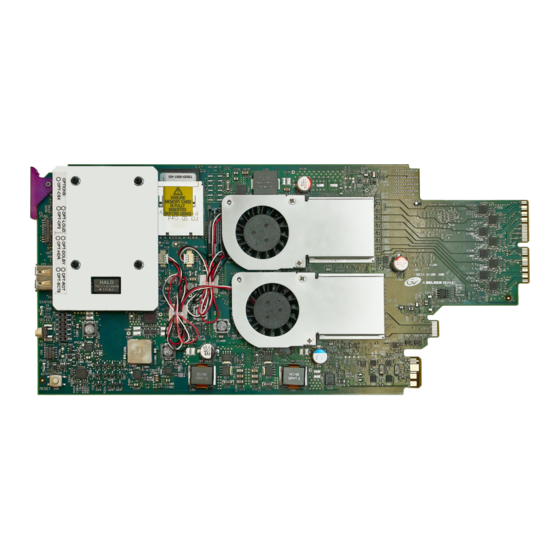
Page 132: Replacing Kmx-3921 Card Fans
Maintenance & Troubleshooting Replacing KMX-3921 Card Fans Replacing KMX-3921 Card Fans The location of the fans on the card are shown below. The location of the card’s part number and serial number is also shown. Note: Some cards may be equipped with only one fan. DPS Fan / Heatsink Power... - Page 133 KMX-3921 Installation & Service Manual Required Tools The following field-supplied material is required: • Compressed air to remove dust from the card. • Flashlight to perform a visual inspection to confirm fan rotation. • Phillips screwdrivers: • #1 jeweler’s screwdriver with a miniature shaft to remove the fan from the fan cover assembly and install the replacement fan back onto the fan cover assembly.
- Page 134 Maintenance & Troubleshooting Replacing KMX-3921 Card Fans are routed through wire holders, remove the wires from the holders first, before disconnecting. Fan Power Connector Plug Fan Power Connector Jack 4 Free up the fan cover assembly by removing the 2 screws in the middle. Once the 2 screws are removed, remove the fan cover assembly.
-
Page 135: Generating A System Snapshot
KMX-3921 Installation & Service Manual 5 Flip the fan cover over, and remove the last screw holding the fan with the #1 Phillips screwdriver. 6 Remove any accumulated dust from the card with compressed air. 7 Replace the fan with the new one, and replace all screws, in the reverse order. 8 Route the fan’s power wires through the wire holders, and make the connection to the card’s fan power connector. -
Page 136: Upgrading The Multiviewer
Maintenance & Troubleshooting Upgrading the Multiviewer The XAdmin Status and Options page appears. 2 Click the Help & support link in the navigation pane. The Technical Support page appears. Click here ... or here 3 Click system snapshot. The system snapshot generation may take a few moments, after which your browser prompts you to save the resulting compressed folder to your hard drive. -
Page 137: Pre-Upgrade Checklist
KMX-3921 Installation & Service Manual Pre-upgrade Checklist IMPORTANT Back up your system database Before upgrading the multiviewer system, make sure you have a backup of the current system database so that you can return to the previous Kaleido Software version if necessary. Refer to Creating a Backup in the Kaleido Software User’s Manual, for details. - Page 138 Maintenance & Troubleshooting Installing a Kaleido Software Upgrade Manager, so that they are all upgraded simultaneously and only one multiviewer reboot will be required. 1 Locate the KMX-3921 card(s) that belong to the multiviewer system you are upgrading. KMX-3921 If you have more than one multiviewer system in theDensité...
-
Page 139: Troubleshooting
KMX-3921 Installation & Service Manual Troubleshooting Troubleshooting with the card's front edge USB connector A USB mouse can be directly connected to the multiviewer card for troubleshooting purposes (as opposed to connecting the mouse to a Kaleido-RCP2, for instance) with the following conditions. -
Page 140: Troubleshooting Common Issues
Maintenance & Troubleshooting Troubleshooting Common Issues Troubleshooting Common Issues Troubleshooting consists of using fault-isolation techniques to narrow down the probable cause to a specific multiviewer component. Schedule these maintenance operations during off hours when the system is not in use if possible as troubleshooting can cause outage. Use the following troubleshooting table to diagnose common issues and take corrective actions to restore operation. - Page 141 KMX-3921 Installation & Service Manual Symptom Probable cause Test Corrective action Occasional frame Loss of Genlock signal System will switch over to Make sure that the external repeats. its internal frame rate. See reference is connected to the the reference source multiviewer.
- Page 142 Maintenance & Troubleshooting Troubleshooting Common Issues In an attempt to restore multiviewer operation and to perform fault isolation procedures, you can normal swap the position of a power supply around in the multiviewer frame to see if multiviewer operation can be restored. If the frame has an empty power supply slot (for example, for a redundant power supply unit (PSU)), you can remove the PSU from the frame and insert it into the other power supply slot.
-
Page 143: Specifications
> 15 dB up to 270 MHz Alignment jitter (100 kHz) < 0.2 UI Timing jitter (10 Hz) < 1 UI Cable length 250 m (820 ft) (Belden 1694A) 150 m (492 ft) (Belden 1855A) HD-SDI inputs Signal SMPTE ST 292-1 (1.485, 1.485/1.001 Gbps) Formats 720p29.97, 720p30, 720p50, 720p59.94... - Page 144 Timing jitter (10 Hz) < 1 UI Cable length 100 m (328 ft) (Belden 1694A) 45 m (148 ft) (Belden 1855A) a. The Kaleido Software does not distinguish between 1080PsF25 and 1080i50, between 1080PsF29.97 and 1080i59.94, between 720p29.97 and 720p30, and between 1080p29.97 and 1080p30. On the monitor wall and in XAdmin’s Status and Options page, 1080PsF25 is reported as 1080i50,...
-
Page 145: Discrete Audio Inputs
AES10-2008 Sampling frequency 48 kHz nominal, 64 channels, synchronous with video reference signal Cable length 300 m (975 ft) (Belden 8281 or Belden 1694A) Connector Coaxial via DIN 1.0/2.3, 75 Ω See also Multiviewer SDI / MADI Input Combinations, on page 21. -
Page 146: Mosaic Outputs
Specifications Mosaic Outputs Mosaic Outputs Mosaic Outputs - General Parameter Description Delay Referenced: • 16.7 ms @ 59.94 Hz • 20 ms @ 50 Hz Free running: • 33 ms @ 59.94 Hz maximum • 40 ms @ 50 Hz maximum Formats •... -
Page 147: Electrical
KMX-3921 Installation & Service Manual Fiber SFP (optional) Parameter Description Number of outputs Up to 2 per SFP module Formats 1080p59.94, 1080p50, 1080i59.95, 1080i50 For more SFP fiber options refer to http://www.grassvalley.com/products/sfp_optical_plug- in_cartridges. See also Grass Valley’s DXF-300 Optical AV Media Extender. -
Page 148: Physical
Specifications Physical Physical Environment Parameters Value Full specification temperature 0–40°C (32–104°F) (ambient) range Maximum storage humidity 90% RH non-condensing Maximum functional humidity 65% RH non-condensing Each optional SFP module typically weighs 75 grams maximum. Refer to the SFP module’s datasheet for more information. KMX-3921 Weight (without SFP Module) Multiviewer Capacity Multiviewer Cards KMX-3921 rear panel Total weight... -
Page 149: Multiviewer Integration With Other Systems And Equipment
KMX-3921 Installation & Service Manual Multiviewer Integration with other Systems and Equipment A number of configurable services are available to establish communications between the multiviewer and a wide variety of devices. Note:This multiviewer does not have an RS-232 serial port for use with other systems and equipment. -
Page 150: Drivers For Controlling Tally Interface Devices From The Multiviewer
Specifications Drivers for Controlling Tally Interface Devices from the Multiviewer Text database Company Protocol download Routers/Controllers Nevion (Network Network Modular (Ethernet) VikinX Modular Electronics) PESA USP (Unsolicited Status Cheetah, Tiger, Jaguar, Protocol) Cougar, Ocelot, Bobcat, TDM3000, PERC2000 system controller Grass Valley (SAM / General Switcher Protocol Snell / Pro-Bel) (SW-P-02) -
Page 151: Drivers For Timers
KMX-3921 Installation & Service Manual UMD controllers Company Device/System Image Video TSI-1000 Tally System Interface (requires option from Image Video) UMD Controller (TCP/IP or UDP/IP) IP Limitation: only one screen index can be received per unicast port. Automation systems Company Device/System Sundance Digital Fastbreak NXT Automation (requires option from Sundance... - Page 152 Specifications Built-in Communications Protocols...
-
Page 153: Appendix A Installing The Sfp Output Module
Installing the SFP Output Module Introduction Installing and removing the SFP output interface cartridge requires special care. This annex describes the process. Rear panels incorporate one or two SFP interface(s). The interface consists of two parts: • A socket on the rear panel into which an SFP interface module is plugged •... -
Page 154: Connecting The Fiber Optic Cables
Installing the SFP Output Module Connecting the fiber optic cables 2 Position the SFP module so that the recessed slot is lined up with the tab side of the socket. 3 Slide the module straight into the socket, and push gently until it clicks into position. Connecting the fiber optic cables 1 Remove the dust plug from the SFP module if present 2 Verify that the exposed end of the optical fiber in the LC connector is clean... -
Page 155: Removing The Sfp Module
KMX-3921 Installation & Service Manual Removing the SFP module 1 Move the bale clasp lever to the open position. Bale Clasp 2 Grasp the SFP module between your thumb and forefinger, and pull it straight out of the slot. • Do NOT pull on the bale clasp lever to remove the module, as it is easily damaged. •... -
Page 156: Contact Us
Contact Us Grass Valley Technical Support For technical assistance, contact our international support center, at 1-800-547-8949 (US and Canada) or +1-530-478-4148. To obtain a local phone number for the support center nearest you, consult the Contact Us section of Grass Valley’s website (www.grassvalley.com). An online form for e-mail contact is also available from the website.
Need help?
Do you have a question about the Grass Valley KMX-3921 and is the answer not in the manual?
Questions and answers