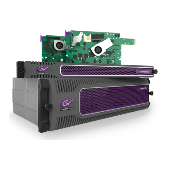
Belden Grass Valley Kaleido-Modular-X Hardware Description & Installation Manual
High picture count, ultra-flexible and scalable multiviewer
Hide thumbs
Also See for Grass Valley Kaleido-Modular-X:
- Installation & service manual (230 pages) ,
- Hardware description & installation manual (96 pages)

Subscribe to Our Youtube Channel
Related Manuals for Belden Grass Valley Kaleido-Modular-X


Summary of Contents for Belden Grass Valley Kaleido-Modular-X
- Page 1 KALEIDO-MODULAR-X HIGH PICTURE COUNT, ULTRA-FLEXIBLE AND SCALABLE MULTIVIEWER Hardware Description & Installation Manual M933-9802-107 2015-06-01...
- Page 2 Copyright & Trademark Notice Copyright © 2013–2015, Grass Valley USA, LLC. All rights reserved. Belden, Belden Sending All The Right Signals, and the Belden logo are trademarks or registered trademarks of Belden Inc. or its affiliated companies in the United States and other jurisdictions.
- Page 3 Electrostatic Discharge (ESD) Protection Electrostatic discharge occurs when electronic components are improperly handled and can result in intermittent failure or complete damage adversely affecting an electrical circuit. When you remove and replace any card from a frame always follow ESD-prevention procedures: •...
- Page 4 Notices Certification and Compliance Electromagnetic Compatibility This equipment has been tested for verification of compliance with FCC Part 15, Subpart B requirements for class A digital devices. Note: This equipment has been tested and found to comply with the limits for a Class A digital device, pursuant to Part 15 of the FCC rules.
- Page 5 X: 表示该有毒有害物质至少在该部件的某一均质材料中的含量超出 SJ/T 11363-2006 规定的限量要求。 X: Indicates that this toxic or hazardous substance contained in at least one of the homogeneous materials for this part is above the limit requirement in SJ/T11363-2006. 技术条款解释:此声明所依据之数据由 Grass Valley 环境管理部门向我们的部件供 应商获取。Grass Valley 公司相信此信息的正确性,但由于数据来源于公司外部,我 们无法保证它的完整和准确。所有这些特性可能在未获通知的情况下更改。 Technical explanations: This statement is based on the information provided by our suppliers of components and collected through our Grass Valley’s environmental management system.
-
Page 7: Table Of Contents
Table of Contents 1 Installation..........1 Introduction. - Page 8 Table of Contents 3 Specifications ......... 49 Kaleido-Modular-X Input Cards .
-
Page 9: Installation
Installation The Kaleido-Modular-X offers a flexible and scalable multiviewer solution for TV production optimized for the space, power and weight considerations found in studios and outside broadcast trucks. Introduction The Kaleido-Modular-X supports up to 64 video inputs, and up to four multiviewer outputs. Features Kaleido-Modular-X features Space-efficient... -
Page 10: Available Options
Installation Available Options Kaleido-Modular-X features (continued) Seamless Kaleido multiviewers can be mixed and matched to create a seamless control across monitoring system across a facility. multiple Choice of control options such as the standalone Kaleido-RCP2 or RCP-200 multiviewers panels, integrated with router control systems and panels, iControl, and third-party control systems. - Page 11 Kaleido-Modular-X Hardware Description & Installation Manual Kaleido-Modular-X configuration with 16 inputs and 2 outputs Kaleido-Modular-X configuration with 32 inputs and 4 outputs Kaleido-Modular-X input and output modules can be housed in the same physical Densité frame, or in multiple frames, allowing expansion beyond the number of slots available within a single frame.
- Page 12 Installation Overview of the Kaleido-Modular-X System Input module parts Description KMX-3901-IN-8-D 8 input HD/SD-SDI and 3 Gbps input module with dual FlexBridge outputs. KMX-3901-IN-8-D-3TRP Triple rear connector panel with bypass relay. KMX-3901-IN-16-D 16 input HD/SD-SDI and 3 Gbps input module with dual FlexBridge outputs.
-
Page 13: Physical Interface
Kaleido-Modular-X Hardware Description & Installation Manual Kaleido-Modular-X functional block diagram: KMX-3901-OUT output modules (KMX-390-OUT-D, and KMX-3901-OUT-S) Physical Interface Frame interface When the frame door is closed, the status LED on each of the cards in the frame is visible via a light pipe in the door. - Page 14 Installation Physical Interface 3901-OUT Output Card Interface, on page 37, for more information. SDI LEDs 1–8 SDI LEDs 9–16 Boot status 1 Status LED Boot status 2 (not used) Select button Power LED ABT LED REF LED Input card, left side Input card, right side Summary view of the interface on the left side, and on the right side of a KMX-3901-IN input card Output card, right side (or...
-
Page 15: Mechanical Installation
Kaleido-Modular-X Hardware Description & Installation Manual Mechanical Installation Unpacking Make sure the following items have been shipped with your Kaleido-Modular-X order. If any of these are missing, contact your distributor or Grass Valley (see Contact Us, on page 59). • 1–4 KMX-3901-IN input cards with matching rear modules, as per order (see Input module parts, on page 4) - Page 16 Installation Unpacking Note: In line with our commitment to environmental preservation, only the Quick Start Guide for your multiviewer model, and some ancillary documents (e.g. welcome letters, warranty cards) are distributed in printed form. All manuals and the Release Notes are available on the DVD that shipped with your multiviewer.
-
Page 17: Installation In The Densité Frame
Kaleido-Modular-X Hardware Description & Installation Manual Installation in the Densité Frame The KMX-3901-IN input cards, the KMX-3901-OUT output cards and their associated rear connector panels must be installed in a Densité 3 frame. Output cards and their rear panel may also be installed in a Densité 3+ FR1 frame. It is not necessary to switch off the frame’s power when installing or removing a card. -
Page 18: Signalling
Installation Signalling Signalling Output Cards The KMX-3901-OUT cards are output modules that can be installed in a Densité 3, Densité 3+ FR1, or Densité 3 mini frame, to be part of a Kaleido-Modular-X multiviewer system. Within a Kaleido-Modular-X system an output card can be designated as either Output A, or Output B. - Page 19 Kaleido-Modular-X Hardware Description & Installation Manual KMX-3901-OUT-D-3DRP rear panel The following table lists the function of each connector associated with the output heads. Connector label Connector Head 1 Head 2 type Function FLEXBRIDGE IN 1 FLEXBRIDGE IN 2 DIN 1.0/2.3 Connection carrying a 3G SDI signal, which contains the mosaic from the input cards (without graphical elements, i.e., no...
- Page 20 Installation Output Cards RJ-45 DE-9 male DE-9 female Pinout of an RS-422 Pinout of straight adapter (Grass Pinout of RS-422 port’s RJ-45 connector Valley part no. 1737-3000-102) connector on SMPTE on the multiviewer slave device Standard wiring between multiviewer and devices wired to SMPTE “slave” specification (e.g. most routers, Ross Synergy switchers, Nevion ETH-CON) RJ-45 DE-9 male DE-9 female...
- Page 21 Kaleido-Modular-X Hardware Description & Installation Manual KMX-3901-OUT-D-3+SRP rear panel Notes • The single rear connector panel KMX-3901-OUT-D-3+SRP does not have a serial port. To support a serial device, your Kaleido-Modular-X system must have at least one output card with a double rear connector panel (KMX- 3901-OUT-D-3DRP).
-
Page 22: Input Cards
Installation Input Cards Output card, right side (or bottom, if in a 1RU frame) Other side: ETH com LED (future use) CPU 0 LED (not used) CPU 1 LED SD card access LED Heartbeat LED USB connector Status LED Select button Power LED Input Cards The KMX-3901-IN cards are input modules... - Page 23 Kaleido-Modular-X Hardware Description & Installation Manual KMX-3901-IN-8-D-3TRP rear panel KMX-3901-IN-16-D-3QRP rear panel...
- Page 24 Installation Input Cards KMX-3901-IN-16-Q-3PRP rear panel Connector label Connector type Function 3G/HD/SD IN 1 to DIN 1.0/2.3 SD-SDI, HD-SDI, or 3G-SDI video inputs 1 to 16 3G/HD/SD IN 16 ABT/MADI IN DIN 1.0/2.3 Multiplexed audio from an external device (Audio Bridge Terminal) LTC IN DIN 1.0/2.3...
- Page 25 Kaleido-Modular-X Hardware Description & Installation Manual Connector label Connector type Function FLEXBRIDGE OUT B1, DIN 1.0/2.3 Connections carrying the 3G SDI signals, which FLEXBRIDGE OUT B2 contains the mosaic (without graphical elements, i.e., no audio meters, no UMDs, etc.) resulting from any upstream input cards and the current input card, for two heads of the system.
- Page 26 Installation Input Cards KMX-3901-IN-M3-Q-3PRP rear panel Connector label Connector type Function M3 IN SD-SDI, HD-SDI, or 3G-SDI video inputs 1 to 16 from NVISION router output module. See NV8500 M3 Backplane Connections below to determine the correct mapping between router outputs and multiviewer inputs, when using the M3 cable.
- Page 27 Kaleido-Modular-X Hardware Description & Installation Manual Connector label Connector type Function FLEXBRIDGE IN B1, DIN 1.0/2.3 Connections carrying the 3G SDI signals, which FLEXBRIDGE IN B2 contains the mosaic (without graphical elements, i.e., no audio meters, no UMDs, etc.) from an upstream input card, for two heads of the system.
-
Page 28: 4K Uhd Prescaler
Installation 4K UHD Prescaler Refer to the NV8500 Series User’s Guide (part no. UG0034) for more information on the M3 output card and backplane module. 4K UHD Prescaler On the KMX-3901-IN-16Q configured as a 4K UHD prescaler, the input connectors 3G/HD/SD IN 3, 4, 7, 8, 11, 12, 15, and 16 are not used. -
Page 29: Gpi-1501 General Purpose Interface I/O Module
Kaleido-Modular-X Hardware Description & Installation Manual Prescaled signal B output 4K UHD signal A inputs 4K UHD signal B inputs Prescaled signal A output GPI-1501 General Purpose Interface I/O Module A GPI-1501 card supports 20 GPI inputs, and 8 configurable GPI input/output terminals. The associated rear panel holds a DB-44 connector, through which all signal inputs and outputs are routed. -
Page 30: Maintenance
Installation Maintenance DB-44 connector For ease of connection, you may use the GPI-1501-TBA terminal block adapter with integral 44-pin connector. Refer to the GPI-1501 Guide to Installation and Operation (available on the Kaleido-X DVD that shipped with your system, and from the Documentation Library section of Grass Valley’s website), for more information. -
Page 31: Replacing Cards
Kaleido-Modular-X Hardware Description & Installation Manual Densité 3+ FR1 frame with open door Opening the front door To open the door • Turn both thumbscrews counterclockwise until they release, and then pull the door away from the front of the frame. Removing the front door To remove the door •... - Page 32 Installation Replacing Cards Replacing rear connector panels To replace a rear connector panel in a Densité 3+ FR1 frame 1 If cards are already installed in the housing frame whose rear panel is being changed, remove them (see Removing a card, on page 24).
- Page 33 Kaleido-Modular-X Hardware Description & Installation Manual 2 Tilt the swivel handle, on the front of the card you wish to remove, to lever the connectors apart, and then use the handle to pull the card straight out of the slot. 3 Close the front door of the frame (see Closing the front door, on page 23).
-
Page 34: 4K Uhd Prescaler Configuration And Upgrade
Installation 4K UHD Prescaler Configuration and Upgrade 4K UHD Prescaler Configuration and Upgrade Converting a KMX-3901-IN-16-Q Input Card to a 4K UHD Prescaler To configure a KMX-3901-IN-16-Q input card as a 4K UHD prescaler 1 Press the Select button on the front edge of the KMX-3901-IN-16-Q input card you wish to configure. -
Page 35: Replacing The Cpu-Eth2 Controller Card
Kaleido-Modular-X Hardware Description & Installation Manual The Status LED on the selected card flashes orange, and the associated control menu appears on the LCD display of the Densité frame’s local control panel. 2 On the local control panel, press the [–] button. CONFIG appears on the LCD display. -
Page 36: Replacing A Gpi-1501 Card
Installation Replacing a GPI-1501 Card • Hook your finger through the opening at the top of the card. In a Densité 3+ FR1 frame, the controller card is located on the upper left-hand side of the frame, above the left-hand power supply. •... -
Page 37: Replacing Frame Ventilation Fans
Kaleido-Modular-X Hardware Description & Installation Manual To install or change a power supply module in a Densité 3 frame 1 Open the front door of the frame (see Opening the front door, on page 23). 2 Remove the controller card, to provide access to the power supply slots (see Replacing the CPU-ETH2 Controller Card, on page 27). - Page 38 Installation Replacing Frame Ventilation Fans Grass Valley uses two different fan units for this product. While they are electrically equivalent, they have slightly different dimensions. The fan is installed with two screws located on opposite corners. The mounting plate has two sets of corner holes —...
-
Page 39: Replacing The Air Filter
Kaleido-Modular-X Hardware Description & Installation Manual The two ventilator fans are mounted at different angles, as shown in the above figure. 3 Align the circuit board on the fan assembly with the notches in the edge of the rear-panel opening (see arrows in figure at right) to ensure the correct alignment. -
Page 41: Operation
Operation The Kaleido-Modular-X can be controlled in different ways: • In the housing frame, you can monitor card operating status of your Kaleido-Modular-X input and output cards by looking at the card-edge LEDs (see Interface, on page 34), and use the Densité CPU-ETH2 local control panel and its buttons to navigate menus and adjust parameter values (see Using the Densité... -
Page 42: Led Interface
Operation LED Interface LED Interface KMX-3901-IN Input Card Interface SDI LEDs 1–8 SDI LEDs 9–16 Boot status 1 Status LED Boot status 2 (not used) Select button Power LED ABT LED REF LED Input card, left side Input card, right side Summary view of the interface on the left side, and on the right side of a KMX-3901-IN input card Input card Status LED The Status LED is located on the front edge of a Kaleido-Modular-X card, immediately... - Page 43 Kaleido-Modular-X Hardware Description & Installation Manual status menu reports that an update is in progress, then you know that you should not interrupt this process (by reseating the card, for example). Input card power LED Monitors the status of the 1.8V and 3.3V power supplies on board the Kaleido-Modular-X card.
-
Page 44: 4K Uhd Prescaler Card Interface
Operation 4K UHD Prescaler Card Interface Boot status LED 2 This LED is always red, and currently not relevant. Input card FlexBridge input LEDs Kaleido-Modular-X input cards have 2 or 4 LEDs (depending on card model) monitoring the status of the FlexBridge inputs located on their rear connector panel. Flexbridge input LEDS on quintuple rear panel (layout is similar on the other rear panels) Meaning... -
Page 45: Kmx-3901-Out Output Card Interface
Kaleido-Modular-X Hardware Description & Installation Manual KMX-3901-OUT Output Card Interface Output card, right side (or bottom, if in a 1RU frame) Other side: ETH com LED (future use) CPU 0 LED (not used) CPU 1 LED SD card access LED Heartbeat LED USB connector Status LED... - Page 46 Operation KMX-3901-OUT Output Card Interface Output card power LED Monitors the status of the power supplies on board the Kaleido-Modular-X card. Meaning Green Failure of an on-board PSU, or there was a glitch on the 3.3V PSU (in which case reseating the card may resolve the problem). In the first case, reseating the card will not resolve the problem.
-
Page 47: Using The Densité Frame Control Panel
Kaleido-Modular-X Hardware Description & Installation Manual Flexbridge input Flexbridge input LEDs 1 and 2, on LEDs 1 and 2, on double rear panel single rear panel Meaning Green HD-SDI or 3G-SDI signal detected No SDI signal detected SFP LEDs Kaleido-Modular-X output cards have 2 or 4 SFP LEDs (depending on rear model) located on their rear connector panel. -
Page 48: Navigating The Local Control Panel Menu
Operation Navigating the Local Control Panel Menu Densité CPU-ETH2 local control panel The panel is assigned to operate any card in the frame by pressing the Select button on the front edge of that card. The Status LED on the selected card will then be blinking orange. Press the CONTROLLER button on the control panel to select the controller card itself. - Page 49 Kaleido-Modular-X Hardware Description & Installation Manual KMX-3901-OUT output card local menu (continued) HEAD2 {List of resolutions;* = current}** {LINK STATE}** FANS {CPU FAN STATUS}** {FPGA FAN STATUS}** NETWORK SETTINGS FRAME IP ADDRESS EDIT ###.###.###.### NETMASK EDIT ###.###.###.### DEFAULT GW EDIT ###.###.###.### LINK MODE EDIT Auto-negotiate...
-
Page 50: Remote Control Using Icontrol
Operation Remote Control Using iControl Kaleido-Modular-X 4K UHD prescaler local menu STATUS CARD STATUS {CARD STATUS}** OFF INPUT STATUS 1 {FORMAT}** 2 {FORMAT}** 3 {FORMAT}** 16 {FORMAT}** REF STATUS {EXTERNAL | URS | FREE RUN | FLEXBRIDGE}** CONFIG 4K UHD PRESCALER ENABLE DISABLE SFP CONFIG*** SFP OUT 1... - Page 51 Kaleido-Modular-X Hardware Description & Installation Manual Service control panel for a Kaleido-Modular-X input card Info Panel on page 46 for more information. In the KMX-OUT control panel window, there are three main areas: the status icon area, the navigation area, and the operating control area. Status icon area Operating...
-
Page 52: Output Settings Panel
Operation Output Settings Panel • A green control status icon indicates that the card is available for remote control from the service control panel in iControl. • A yellow icon indicates that someone is controlling the card from the control panel on the housing frame (see Using the Densité... -
Page 53: Network Settings Panel
Kaleido-Modular-X Hardware Description & Installation Manual The following table lists some (but not all) output formats supported at the HDMI connections. You can customize your own timing rates for resolutions ranging from 1024 × 768 pixels up to 1920 × 1200 pixels (all progressive scan), by using XEdit. Kaleido-Modular-X HDMI output resolutions Resolution Format name... -
Page 54: Info Panel
Operation Info Panel Click Apply to set these values into the card, or Cancel to leave the original values unchanged. Notes • These settings apply to the rear-panel Ethernet port of the Kaleido- Modular-X output cards; not to the Ethernet ports at the back of the Densité... - Page 55 Kaleido-Modular-X Hardware Description & Installation Manual Label Type a label to identify this Kaleido-Modular-X card when it appears in iControl applications. This label appears in the service panel’s title bar, in iControl Solo, and in the iControl Navigator views Short label Type the shorter label that iControl uses in some cases (8 characters). Source ID Type a descriptive name for this Kaleido-Modular-X card.
- Page 56 Operation Info Panel Three buttons give access to additional information and controls: Details Reports the firmware version, service version, and panel version for this card. Output card Details window Advanced Shows the Long ID for this Kaleido-Modular-X card. The Long ID is the address of this card in the iControl network.
-
Page 57: Specifications
> 15 dB up to 270 MHz Alignment jitter (100 kHz) < 0.2 UI Timing jitter (10 Hz) < 1 UI Cable length 250 m (820 ft) (Belden 1694A) 150 m (492 ft) (Belden 1855A) HD-SDI inputs Signal SMPTE ST 292-1 (1.485, 1.485/1.001 Gbps) Formats 720p29.97, 720p30, 720p50, 720p59.94... -
Page 58: Discrete Audio Inputs
Timing jitter (10 Hz) < 1 UI Cable length 100 m (328 ft) (Belden 1694A) 45 m (148 ft) (Belden 1855A) a. The Kaleido-X software does not distinguish between 1080PsF25 and 1080i50, between 1080PsF29.97 and 1080i59.94, between 720p29.97 and 720p30, and between 1080p29.97 and 1080p30. -
Page 59: Flexbridge Inputs/Outputs
Kaleido-Modular-X Hardware Description & Installation Manual ABT/MADI audio inputs (continued) Cable length 250 m (820 ft) (Belden 1694A) 150 m (492 ft) (Belden 1855A) Connector DIN 1.0/2.3 FlexBridge Inputs/Outputs The KMX-3901-IN-8-D, and KMX-3901-IN-16-D support 2 FlexBridge inputs, and 2 FlexBridge outputs. The KMX-3901-IN-16-Q cards support 4 FlexBridge inputs, and 4 FlexBridge outputs. -
Page 60: Electrical
Specifications Electrical LTC Inputs The KMX-3901-IN cards support one unbalanced LTC input for clock synchronization, or for monitoring a time code source from a timer, VTR, etc. LTC Inputs Signal SMPTE ST 309-1999, SMPTE ST 12-1995 (EBU-3259-E) Level 500 mVp-p to 10 Vp-p Ω... - Page 61 > 10 dB up to 3 GHz Alignment jitter (100 kHz) < 0.3 UI Timing jitter (10 Hz) < 2 UI Cable length 100 m (328 ft) (Belden 1694A) 45 m (148 ft) (Belden 1855A) Connector DIN 1.0/2.3 Video outputs Signal SMPTE ST 424 (2.97, 2.97/1.001 Gbps)
-
Page 62: Kaleido-Modular-X Output Cards
> 15 dB up to 1.5 GHz Alignment jitter (100 kHz) < 0.2 UI Timing jitter (10 Hz) < 2.5 UI Cable length 100 m (328 ft) (Belden 1694A) 45 m (148 ft) (Belden 1855A) Connectors DIN 1.0/2.3 Quantization 8 bits... -
Page 63: Analog Audio Outputs
> 10 dB up to 3 GHz Alignment jitter (100 kHz) < 0.3 UI Timing jitter (10 Hz) < 2 UI Cable length 100 m (328 ft) (Belden 1694A) 45 m (148 ft) (Belden 1855A) Connectors DIN 1.0/2.3 Quantization 8 bits... -
Page 64: Communication
Specifications Communication Communication Ethernet Signal 10/100 BASE-T Standard IEEE 802.3 Connector RJ-45 Serial port Signal RS-422 (SMPTE ST 207, EBU-3245), RS-485 Connector RJ-45 a. Not available on the single rear connector panel Standard USB version 2.0 Peripherals supported Mouse, keyboard, memory stick Connector USB type A Electrical... -
Page 65: Gpi-1501 Gpi I/O Module
Kaleido-Modular-X Hardware Description & Installation Manual GPI-1501 GPI I/O module This card supports 20 GPI inputs, and 8 configurable GPI inputs/outputs. GPI input (up to 20) Description Contact closure to GND Pull-up voltage 2.3 Volts Source current 2 mA when input shorted Low-level activation 0.8 Volts max Over voltage... -
Page 67: Contact Us
Contact Us Grass Valley Technical Support For technical assistance, contact our international support center, at 1-800-547-8949 (US and Canada) or +1 530 478 4148. To obtain a local phone number for the support center nearest you, please consult the Contact Us section of Grass Valley’s website ( www.grassvalley.com An online form for e-mail contact is also available from the website.
Need help?
Do you have a question about the Grass Valley Kaleido-Modular-X and is the answer not in the manual?
Questions and answers