Table of Contents
Advertisement
Quick Links
Advertisement
Table of Contents
Troubleshooting

Related Manuals for Vollrath Stoelting E111I


Summary of Contents for Vollrath Stoelting E111I
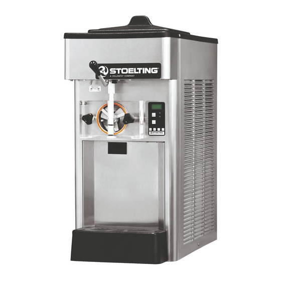
- Page 1 Model E111I / F111I SERVICE MANUAL Manual No. 513663 Nov. 2010...
- Page 3 This manual provides basic information about the machine. Instructions and suggestions are given covering its operation and care. The illustrations and specifi cations are not binding in detail. We reserve the right to make changes to the machine without notice, and without incurring any obligation to modify or pro- vide new parts for machines built prior to date of change.
- Page 4 A Few Words About Safety Safety Information Safety Alert Symbol: Read and understand the entire manual before This symbol Indicates danger, warning or caution. operating or maintaining Stoelting equipment. Attention is required in order to avoid serious per- sonal injury. The message that follows the symbol This manual provides the operator with information contains important information about safety.
-
Page 5: Table Of Contents
TABLE OF CONTENTS Section Description Page Description and Specifications Description ....................1 Specifications ..................... 2 Modes of Normal Operation ................ 3 Mix Level Indicators ..................5 Hopper Refrigeration ................... 5 Motor Profile Cutout Compensation ............5 Installation Instructions Safety Precautions ..................7 Shipment and Transit ................. - Page 6 Section Description Page Refrigeration System Refrigeration System .................. 25 Refrigerant Recovery and Evacuation ............25 Refrigerant Charging ................... 26 Compressor ....................27 Condenser ....................28 Evaporator ....................28 Valves ......................28 Thermostatic Expansion Valve (TXV) ..............28 Check Valve ......................29 High Pressure Cutout ..................
-
Page 7: Description And Specifications
SECTION 1 DESCRIPTION AND SPECIFICATIONS 1.1 DESCRIPTION The Stoelting E111 & F111 counter machines are gravity fed. The machines are equipped with fully automatic con- trols to provide a uniform product. The machines are designed to operate with almost any type of commercial soft serve or non-dairy mix available, including ice milk, ice cream, yogurt, and frozen dietary desserts. -
Page 8: Specifications
SPECIFICATIONS Model E111I Model F111I Dimensions Machine with crate Machine with crate width 15'' (38,1 cm) 19-1/2'' (49,5 cm) 15'' (38,1 cm) 19-1/2'' (49,5 cm) height 35-3/4'' (90,8 cm) 43'' (109,2 cm) 35-3/4'' (90,8 cm) 43'' (109,2 cm) depth 28-3/4'' (73,0 cm) 33-1/2'' (85,1 cm) 28-3/4'' (73,0 cm) 33-1/2'' (85,1 cm) -
Page 9: Modes Of Normal Operation
1.3 MODES OF NORMAL OPERATION Following are details of the operational modes of the IntelliTec control. NOTE: The preset amounts, times, and temperatures listed below are references to actual settings on the IntelliTec control. Refer to Table 1-1 on page 7 for details on each setting. - Page 10 The "Standby Mode" maintains product quality during slow times, while minimizing reactivation time. This mode lasts for a preset time (Stb Time). Once this time has been reached without user interruption, the control moves into the "Sleep 1 Mode". Refer to Figure 1-4 for a graphical representation of the "Standby Mode".
-
Page 11: Mix Level Indicators
H. Clean Mode A. Serve and Standby Mode When the CLEAN button is pressed, freezing cylinder In the event of a temperature sensor failure on a freezing refrigeration stops, the drive motor starts and will run for cylinder, the IntelliTec control will function in two modes, 20 minutes, and a 5 minute countdown timer is displayed. - Page 12 IntelliTec Control Setting Specifications Basic Menu DISPLAY E111 F111 MODE DEFINITION CutOut Serve Amp draw setting for cut out Cut In T 18°F 21°F Serve Temperature setting for cut in Cycles Serve Freezing cycles before going into Standby Mode Stir On 15 sec 15 sec Serve...
-
Page 13: Installation Instructions
SECTION 2 INSTALLATION INSTRUCTIONS 2.1 SAFETY PRECAUTIONS If danger, warning or caution labels are needed, indicate the part number, type of label, location of label, and quantity Do not attempt to operate the machine until the safety required along with your address and mail to: precautions and operating instructions in this manual are read completely and are thoroughly understood. -
Page 14: Shipment And Transit
2.2 SHIPMENT AND TRANSIT Place the OFF-ON switch in the OFF position. The machine has been assembled, operated and inspected Connect the power cord to the proper power at the factory. Upon arrival at the final destination, the supply. Check the nameplate on your machine for complete machine must be checked for any damage which proper supply. -
Page 15: Initial Setup And Operation
SECTION 3 INITIAL SETUP AND OPERATION 3.1 OPERATOR’S SAFETY PRECAUTIONS 3.2 OPERATING CONTROLS AND INDICATORS SAFE OPERATION IS NO ACCIDENT; observe these rules: Before operating the machine, it is required that the operator know the function of each operating control. Refer Know the machine. - Page 16 Main Freezer Power OFF-ON Switch Dispense Rate Adjustor The Main Freezer Power OFF-ON switch is a two The dispense rate adjuster limits the opening of the position toggle switch used to supply power to the spigot. To adjust product dispense rate, turn the control circuit.
-
Page 17: Important Information Regarding Cleaning And Sanitizing
3.3 IMPORTANT INFORMATION REGARDING SANITIZING CLEANING AND SANITIZING • Kills bacteria. Soft serve and shake machines require special consider- • Can be effective on clean surfaces only. ation when it comes to food safety and proper cleaning and NOTE sanitizing. Using a SANITIZER on an unclean surface will not The following information specifically covers issues for guarantee a clean and safe frozen dessert machine. -
Page 18: Disassembly Of Parts
MACHINE DAMAGE – Strong acids will attack Inspection for worn or broken parts should be made each metal and rubber causing premature wear of parts. time the machine is disassembled. All worn or broken parts The use of a delimer needs to be closely monitored should be replaced to ensure safety to both the operator and to avoid damage to machine surfaces and parts. -
Page 19: Cleaning Disassembled Parts
3.5 CLEANING DISASSEMBLED PARTS Disassembled parts require complete cleaning, sanitizing and air drying before assembling. Local and state health codes will dictate the procedure required. Some state health codes require a four sink process (pre-wash, wash, rinse, sanitize, air dry), while others require a three sink process (without the pre-wash step). -
Page 20: Assembling The Machine
Remove the drip tray by pulling from the front panel. Clean and replace the drip tray. 3.8 ASSEMBLING MACHINE To assemble the machine parts, refer to the following steps: NOTE Petrol Gel sanitary lubricant or equivalent must be used when lubrication of parts is specified. NOTE The United States Department of Agriculture and the Food and Drug Administration require that lubri-... -
Page 21: Sanitizing
3.9 SANITIZING Sanitizing must be done after the machine is cleaned and just before the hopper is filled with mix. Sanitizing the night before is not effective. However, you should always clean the machine and parts after each use. THE UNITED STATES DEPARTMENT OF AGRICULTURE AND THE FOOD AND DRUG ADMINISTRATION RE- QUIRE THAT ALL CLEANING AND SANITIZING SOLU- TIONS USED WITH FOOD PROCESSING EQUIPMENT... -
Page 22: Normal Freeze Down And Operation
Press the SET button. A cursor will start blinking Press the SET button to save the value. The LCD under the far right digit. will read “CutOut Set -- OK”. Change the value to 8.0. Press the left arrow (⇐) Press the SEL button. -
Page 23: Mix Information
Place the Main Freezer Power OFF-ON switch in the ON position. Press the PUSH TO FREEZE button. NOTE After the drive motor starts, there is a 3-second de- lay before the compressor starts. When the product is at 75% consistency, the display will read “SERVE”. -
Page 25: Maintenance And Adjustments
SECTION 4 MAINTENANCE AND ADJUSTMENTS MACHINE ADJUSTMENT LOCKING THE CONTROL PANEL This section is intended to provide maintenance person- The IntelliTec control has a tamper proof mode to prevent nel with a general understanding of the machine adjust- unauthorized use. When set, all buttons on the control ments. -
Page 27: Readings
Modifying Control Settings Aux. Temp (°F) To change the value of a system function, locate the This reading provides the ambient temperature function on the IntelliTec Settings Menu and follow the around the IntelliTec control. steps below. Supply V (VAC) IMPORTANT: A calculated input voltage is recorded. -
Page 28: Adjustments
Up Time (hours) Cut In T (°F) This value is a record of the total time the machine After the consistency value has been determined, has been in service. If power is interrupted, the the Cut In T value can be adjusted. The Cut In T timer will stop until power is restored. -
Page 29: Drive Belt Tension Adjustment
Off Time (sec) DRIVE BELT TENSION ADJUSTMENT Increasing this value will increase the time between To check belt tension, refer to Figure 4-3 and follow the freezing cycles in "Standby Mode" and result in an steps below: increase of product temperature in the barrel. Stb Time (sec) WARNING This setting determines the total amount of time in... -
Page 30: Condenser Cleaning
CONDENSER CLEANING 4.11 EXTENDED STORAGE The air-cooled condenser is a copper tube and aluminum fin Refer to the following steps for storage of the machine over type. Condensing is totally dependent upon airflow. A any long period of shutdown time: plugged condenser filter, condenser, or restrictions in the Clean thoroughly with warm detergent all parts louvered panel will restrict airflow. -
Page 31: Refrigeration System
SECTION 5 REFRIGERATION SYSTEM 5.1 REFRIGERATION SYSTEM NOTE For qualified service personnel only. Anybody work- The E111 & F111 refrigeration systems have two functions: ing with refrigerants must be certified as a Techni- Medium-Temperature - Maintaining product cian TYPE I as required by 40 CFR 82 Subpart F temperature in the hopper. -
Page 32: Refrigerant Charging
NOTE A. REFRIGERANT RECOVERY If evacuation is not completed after 20 minutes, press Disconnect the machine from electrical supply the Push To Freeze button again. This will keep the before removing any panels for servicing. solenoid valves open. Remove all panels. If the system will not maintain a standing vacuum Connect the recovery unit to the suction and test with the vacuum pump off (gauge increases... -
Page 33: Compressor
5.4 COMPRESSOR B. COMPRESSOR REMOVAL Disconnect the machine from electrical supply The E111 & F111 have hermetic reciprocating compressors before removing any panels for servicing. (Refer to Figure 5-2). Details of the compressors’ starting components are in Section 6. WARNING Hazardous voltage The Main Freezer Power switch must be placed in the OFF position when disassembling for servic-... -
Page 34: Condenser
Leave the suction and discharge ports open to prevent pressure buildup. Braze the suction and discharge line to the compressor. Connect the wires to the compressor terminals. Replace the drier per the instructions in Section 5.9. Evacuate the system per the instructions in Section Recharge the system per the instructions in Section 5.3. -
Page 35: Check Valve
TXV REMOVAL B. CHECK VALVE Disconnect the machine from the electrical supply The refrigeration system has 2 magnetic check valves before removing any panels for servicing. (Refer to Figure 5-4). Each valve is positioned in the suction line and prevents backflow of refrigerant into an evaporator. Remove the side panel. -
Page 36: Hot Gas Bypass
HIGH PRESSURE CUTOUT REMOVAL HOT GAS BYPASS ADJUSTMENT Remove the front panel. NOTE Recover refrigerant charge per instructions in Before adjusting the hot gas bypass, check the EPR Section 5.2. valve and adjust if necessary. Leave the suction and discharge ports open to Turn the Main Power OFF/ON switch to the OFF prevent pressure buildup during removal. -
Page 37: Evaporator Pressure Regulator (Epr)
Remove the heat sink from the hot gas bypass. Remove the heat sink from the hot gas bypass. Replace the filter drier. Refer to Section 5.8 for Replace the filter drier. Refer to Section 5.8 for details. details. Evacuate and recharge system per instructions in Evacuate and recharge system per instructions in Section 5.2. -
Page 38: Solenoid
Remove the clamps from the water lines at the valve. Remove the two screws holding the water valve to the frame and remove the valve. WATER VALVE REPLACEMENT To replace the water valve, perform the following proce- dures: Position the water valve and attach to the frame Figure 5-10 Suction Line Solenoid using the two screws. -
Page 39: Filter Drier
Remove insulation around valve and attached FILTER DRIER REMOVAL refrigeration lines. Apply heat sinks (wet cloth) to the insulated WARNING refrigerant lines near the valve. Hazardous voltage The Main Freezer Power switch must be placed in CAUTION the OFF position when disassembling for servic- ing. - Page 40 Leave a port open to prevent pressure buildup during capillary tube removal. Remove foam insulation from the capillary tube at the evaporator inlet. Unsweat the capillary tube and remove. CAPILLARY TUBE REPLACEMENT Position the capillary tube in the refrigeration system. Apply a heat sink (wet cloth) to the capillary tube.
-
Page 41: Electrical And Mechanical Control Systems
SECTION 6 ELECTRICAL AND MECHANICAL CONTROL SYSTEMS NOTE The wiring diagram is available in Section 8. INTELLITEC CONTROLLER Understanding the modes of operation and individual con- trol settings will make servicing the control straight forward. COMPONENTS OF CONTROLLER The IntelliTec control consists of three main components; the control board (Figure 6-1), the membrane switch (Figure 6-2), and the display panel module (Figure 6-3). -
Page 42: Drive Motor
A. CONTACTOR TESTS The following tests will show if a contactor is working properly. Remove the header panel and visually check the IntelliTec control board. Check for a signal going to contactor. When the spigot is opened or the Push To Freeze button is Tension pressed, the DRV LED on the control board will Adjustment... -
Page 43: Capacitors
CAPACITORS Measure the capacitance across the terminals. The results should be as follows: The compressor start and run contactors are mounted behind the right side panel. The start and run capacitors for Rating the drive motors are mounted directly onto the motor body. Part Drive Motor (#522858) -
Page 44: Condenser Fan Motor (Air Cooled Models Only)
C. GEARBOX INSTALLATION SPIGOT SWITCH Place the gear box in position from the rear of the The spigot switch is a normally closed, held open switch. machine. Fasten the bolts through the gear box to When a spigot is pulled, the spigot switch sends a signal the rear of the barrel. -
Page 45: Temperature Control Sensor
Replace the dispense rate adjuster knob and tighten. Replace the header panel and secure with the two Phillips head screws. TEMPERATURE CONTROL SENSOR The temperature control sensor is a thermistor used to sense the temperature of the suction line. As the suction line temperature increases, the internal resistance of the thermistor will decrease. -
Page 47: Troubleshooting Error Codes
SECTION 7 TROUBLESHOOTING 7.1 ERROR CODES from a restriction preventing mix from entering the freezing cylinder. Check the mix in the hopper. If When the machine experiences a problem, one of the the level mix is low, add mix. If there is a possibility following error codes will be displayed on the control panel. - Page 48 Error Code 5 - Freezing Cylinder Sensor Error Code 6 - Hopper Sensor (single hopper machines) The Freezing Cylinder Sensor Error (E5) indicates The Hopper Sensor Error (E6) indicates a failure of a failure of the barrel sensor or an extreme out of the hopper sensor or an extreme out of range range condition (<...
- Page 49 Error Code 10 - Auxiliary Sensor An Auxiliary Temperature Sensor Error (R10) occurs if the temperature sensor on the control board fails. Turn the Main Freezer Power Off-On switch Off and back On. Error Code 11 - Low Temperature The Low Temperature Error (E11) occurs when the temperature of the gas refrigerant at the barrel sensor falls below -20°F.
-
Page 50: Troubleshooting - Machine
7.3 TROUBLESHOOTING - MACHINE PROBLEM POSSIBLE CAUSE REMEDY 1. Power to machine is off. 1. Supply power to machine. 2. Blown fuse or tripped circuit. 2. Replace or reset. 3. Freeze-up (auger will not turn). 3. Turn Main Freezer Power OFF for 15 minutes, Machine does not then restart. -
Page 51: Replacement Parts
SECTION 8 REPLACEMENT PARTS AUGER & FRONT DOOR PARTS 666786 381804 694255 624678-5 3170644 3159696 624598-5 E111 - 4157952 F111 - 4157968 149003 625133 2177698 482019 Quantity Part Description E111 F111 149003 Bushing - Front Auger Support 381804 Auger Flight 482019 Knob - Front Door (Black) 624598-5... -
Page 52: Hopper Cover & Trays
HOPPER COVER & TRAYS 314452 744606 744284 624677-5 2149238 744283-SV 232734 Quantity Part Description E111 F111 232734 Cap - Rosette 314452 Cover - Hopper 624677-5 O-Ring - Mix Inlet - Black (5 Pack) 744283-SV Tray - Drip 744284 Insert - Drip Tray 744606 Tray - Drain (Black Plastic) 2149238... -
Page 53: Left Side
LEFT SIDE 2183248 2183422 762978 272065 763423 763589 762329 762455 458003 763482 231078 430165 763128 430172 763422 231095 763433 Quantity Part Description E111 F111 114068 Hook - Condenser Filter Fastening 231078 Capacitor - Run (#522858 Motor) 231095 Capacitor - Start (#522858 Motor) 231108-SV... -
Page 54: Machine Front
MACHINE FRONT 521686-115 521686-230 744142 284071 332541 718532 482004 162077 719025-SV 522291 282043-SV 282046 342004 232091 3158185 490716 Quantity Part Description E111 F111 162077 Blade - Fan (Air-Cooled Condenser) 215061 Plug - Bumper (Drip Tray) 229116 Cable - Phone (Control Board To Display Board) 232091 Cap - Protective (Gray) - #490716... -
Page 55: Machine Back
MACHINE BACK 618151 618534 231026 231027 295017 295019 230631 230634 614233 152293 152307 598245 522858-SV 598072 Quantity Part Description E111 F111 152293 Belt - Gripnotch (AX37) (Each) (60 Hz) 152307 Belt - Gripnotch (AX38) (Each) (60 Hz) 152323 Belt - Gripnotch (AX39) (Each) (50 Hz) 230631 Capacitor - Start (#282043... -
Page 56: Decals & Miscellaneous
DECALS & MISCELLANEOUS Quantity Part Description E111 F111 208135 Brush - 4" X 8" X 16" (Barrel) 208380 Brush - 1/4" X 3" X 14" 208401 Brush - 1" X 3" X 10" 208467 Brush - 3/8" X 1" X 5" 236040 Card - Cleaning Instruction 324105... -
Page 57: Wiring Diagram
WIRING DIAGRAMS... - Page 61 DOMESTIC WARRANTY (Including Mexico) SOFT SERVE / SHAKE EQUIPMENT 1. Scope: PW Stoelting, L.L.C. (“Stoelting”) warrants to the first user (the “Buyer”) that the freezing cylinders, hoppers, compressors, drive motors, speed reducers, and augers of Stoelting soft serve / shake equipment will be free from defects in materials and workmanship under normal use and proper maintenance appearing within five (5) years, and that all other components of such equipment manufactured by Stoelting will be free from defects in material and workmanship under normal use...
Need help?
Do you have a question about the Stoelting E111I and is the answer not in the manual?
Questions and answers