
Subscribe to Our Youtube Channel
Related Manuals for Vollrath STOELTING Flavor Burst STL-80BLD


Summary of Contents for Vollrath STOELTING Flavor Burst STL-80BLD
- Page 1 A VOLLRATH® DIVISION Flavor Burst® Soft Serve System Blended Integrated Operator’s Manual Manual No. 513847...
- Page 3 Flavor Burst Stoelting Ready ® ® 8-Flavor Integrated Soft Serve “Blend” System Model STL-80BLD-INT Equipment, Maintenance and Operations Manual For questions, support, and ordering parts, contact Stoelting Company’s White Glove Service. Phone: 1-800-319-9549 Warranty & Installation Form An installation form is provided with every STL-80BLD-INT system, located inside the unit with this manual.
-
Page 4: Table Of Contents
TABLE OF CONTENTS FCC Conformity Statement..…...………………………………………….………………...3 Introduction……………………………...………………………………………….………….4 Guidelines For The Best Blend......…...…………..………………………4 Safety Precautions……………………………..…………….………..……..….…………..4 Environmental Notices………………...………………………………………….………….5 Parts Identification/Function……...……………………….……..…..……….……..….…..7 Daily Opening Procedures……..………………………….…….…..…….………..……...22 Sanitizing the Blending System………………………….….………………..…...…22 Assembling the Blending Assembly………………...…..………………………...…23 Installing the Blending System…………………………….…….……….……...…...24 Other items to check during opening procedures………….…………………….…25 Daily Closing Procedures………………………………………….……………….………26 Removing the Blending System………………………………..……………...…...26 Disassembling the Blending Assembly………………..……………………….……27... - Page 5 TABLE OF CONTENTS (continued) Equipment Setup……………………………………………………...…..……….……..….48 Mounting the Freezer to the Stoelting Cart............48 Installing the Touch Panel and Mounting Bracket………………………...…..…49 Draw Switch Options……………………………………….………..…………...…51 Installing the Draw Switch Extension…………….………...……………...…51 Installing the Draw Handle Switch…………………….……...…………...…52 Sanitizing the Blending System…………………………..…………...…………...…52 Assembling the Blending Assembly…………..……………………..……...…...…53 Installing the Spout Adapter…………………………….……..…………………...…53 Installing the Blending System and Suspension Bracket………………………..54 Mounting the Tube / Cable Casing Assemblies……………………...………..…56...
-
Page 6: Fcc Conformity Statement
FCC Conformity Statement: This device complies with Part 15 of the FCC Rules. Operation is subject to the following two conditions: (1) this device may not cause harmful interference, and (2) this device must accept any interference received, including interference that may cause undesired operation. Changes or modifications not expressly approved by the party responsible for compliance could void the user's authority to operate the equipment. -
Page 7: Introduction
GUIDELINES FOR THE BEST BLEND INTRODUCTION Congratulations on your purchase of the Flavor The Blend system mixes concentrated syrup Burst Stoelting-Ready flavoring system. As a with base product in a very small area, and in a food and beverage provider, your customers very short amount of time. -
Page 8: Environmental Notices
DO NOT put objects or fingers in the NOISE LEVEL: Airborne noise emission door spout. Failure to follow this instruction may does not exceed 70 dB(A) when measured at a result in contaminated product or personal distance of 1.0 meter from the surface of the machine and at a height of 1.6 meters from the injury from blade contact. - Page 9 PAGE INTENTIONALLY LEFT BLANK...
-
Page 10: Parts Identification/Function
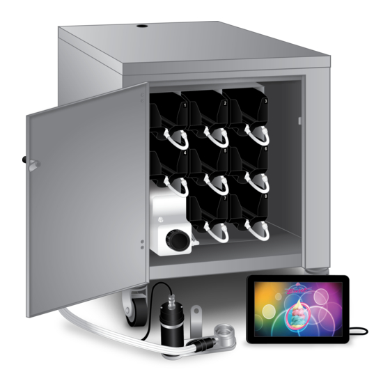
PARTS IDENTIFICATION/FUNCTIONS General System Overview (See Figure 1) ITEM PART NO. DESCRIPTION QTY. FUNCTION TOUCH PANEL ASSEMBLY WITH STOEELE906A Flavor Burst unit command center. BRACKET STOEINJ424STL-BLD FLAVOR BLEND ASSEMBLY Blends syrups into the product. Conceals and protects the Touch Panel STOEMIS3026S TOUCH PANEL CABLE CASING cable, as well as attaches it to the freezer. - Page 11 General System Overview Figure 1...
- Page 12 Integrated Cabinet (See Figure 2) ITEM PART NO. DESCRIPTION QTY. FUNCTION Connects and secures the side and interior STOECAB357 PANEL STABILIZER BRACKET panels of the internal cabinet. STOECAB304L LEFT SIDE CABINET PANEL Holds left side syrup rails. STOECAB304R RIGHT SIDE CABINET PANEL Holds right side syrup rails.
- Page 13 Integrated Cabinet (Continued) Figure 2...
- Page 14 Blending Assembly and Related Parts (See Figure 3) ITEM PART NO. DESCRIPTION QTY. FUNCTION FLAVOR BLEND ASSEMBLY STOEINJ424STL-BLD WITH SYRUP LINES, Transports and blends syrup into product. ADAPTER, & BRACKET STOEINJ422C BLENDING HEAD ASSEMBLY Connects flavor line to inject syrups into product. SMALLER SYRUP PORT O- STOERUB652-RSS 1 ea.
- Page 15 Blending Assembly and Related Parts (Continued) ITEM PART NO. DESCRIPTION QTY. FUNCTION STAINLESS 9-TUBE CASING Protects and holds the cables and 9-Tube STOEMIS3196 ASSEMBLY Assembly in place on the freezer side panel. STAINLESS 9-TUBE CASING Covers and protects the cables and tubes of the 14A STOEMIS3190 1 ea.
- Page 16 Syrup Pump and Related Parts (See Figure 4) ITEM PART NO. DESCRIPTION QTY. FUNCTION SOFT SERVE SYRUP PUMP Pumps syrup from flavor bags to flavor lines. STOESYR307 PERISTALTIC SYRUP PUMP 1 ea. Pumps syrup from flavor bags to flavor lines. STOETUB806 1/8”...
- Page 17 Syrup Pump and Related Parts Figure 4...
- Page 18 Sanitizer Pump and Related Parts (See Figure 5) ITEM PART NO. DESCRIPTION QTY. FUNCTION Connects with flavor line to flush with STOEMIS3028-80M FLUSH TUBE ASSEMBLY sanitizer solution. Connects to the syrup line and sanitizer tank to STOEFIX1051 1/4” ID HOSE BARB ELBOW 2 ea.
- Page 19 Sanitizer Pump and Related Parts Figure 5...
- Page 20 Electronic Parts and Connections (See Figure 6) ITEM PART NO. DESCRIPTION QTY. FUNCTION FLAVOR 10 COLOR TOUCH STOEELE906 Control system for the unit. PANEL TOUCH PANEL MOUNTING STOEMIS 3214 Secures the Touch Panel to the freezer. BRACKET ASSEMBLY STOEMIS3214A TOUCH PANEL MOUNTING PLATE 1 ea. Attaches the Touch Panel to the anchor bracket. STOEMIS3214B MOUNTING ANCHOR BRACKET 1 ea.
- Page 21 Electronic Parts and Connections (Continued) Figure 6...
- Page 22 Spare Parts Kit (See Figure 7) ITEM PART NO. DESCRIPTION QTY. FUNCTION SPARE PARTS KIT – SOFT Houses extra spare parts and wear STOESPR5800STL-BLD SERVE BLEND items. Rotates product for even syrup STOEINJ321C GEAR CARTRIDGE distribution. Provides sealed cavity and prevents STOERUB601 9-POS DUCKBILL CHECK VALVE syrup leakage.
- Page 23 Spare Parts Kit Figure 7...
- Page 24 PAGE INTENTIONALLY LEFT BLANK...
-
Page 25: Daily Opening Procedures
3. Remove each part from the sanitizer DAILY OPENING PROCEDURES solution. Place the items on a sanitary tray to air dry. NOTE: YOUR HANDS SHOULD BE CLEANED AND SANITIZED BEFORE YOU PERFORM THE FOLLOWING PROCEDURES. NOTE: THE FOLLOWING PROCEDURES REQUIRE APPROVED, SERVICEABLE AND SANITIZED TOOLS AND BRUSHES. -
Page 26: Assembling The Blending Assembly
6. The following do not need to be sanitized on 2. Install the Blending Head onto the Gear Box a daily basis as part of the daily opening and rotate off-center to secure. procedures. However, inspect these areas and if necessary, clean according to instructions in the SCHEDULED MAINTENANCE section: ... -
Page 27: Installing The Blending System
Installing the Blending System 4. Connect the Drive Motor cable to the Motor. 1. Install the spout adapter assembly, complete with o-rings, onto the freezer spout. Push up on the adapter with your palm until it snaps on. Ensure it is evenly and fully installed. -
Page 28: Other Items To Check During Opening Procedures
Other items to check during opening procedures These steps do not necessarily need to be performed as part of the daily opening procedures. The following is a list of areas to check on the Flavor Burst ® system during opening procedures. These areas should be checked and adjusted if necessary. -
Page 29: Daily Closing Procedures
2. Rotate the 9-Tube Assembly coupler until it DAILY CLOSING PROCEDURES unlocks and is able to slide out of the Blending Head syrup line opening. NOTE: YOUR HANDS SHOULD BE CLEANED AND SANITIZED BEFORE YOU PERFORM THE FOLLOWING PROCEDURES. NOTE: THE FOLLOWING PROCEDURES REQUIRE APPROVED, SERVICEABLE AND SANITIZED TOOLS AND BRUSHES. -
Page 30: Disassembling The Blending Assembly
5. Remove the Blending Assembly from the Disassembling the Blending Assembly Suspension bracket. 1. Rotate the Drive Motor to unlock and remove the Motor from the Gear Box. NOTE: DO NOT ATTEMPT TO REMOVE THE SPOUT ADAPTER WITH THE ASSEMBLY ATTACHED! USING THE ASSEMBLY OR GEAR BOX AS LEVERAGE MAY BREAK THE 2. -
Page 31: Sanitizing The Blending System
Sanitizing the Blending System 5. When the Gear Box and nut have soaked for at least 5 minutes, brush and clean all 1. Prepare detergent water by mixing several exposed surfaces and openings with drops of Dawn dish soap with a gallon of detergent water and rinse thoroughly with ®... - Page 32 8. Remove each part from the sanitizer 12. Clean, rinse and dry the surfaces of the solution. Place the items on a sanitary tray Drive Motor and exposed surfaces of the to air dry. cabinet using detergent water, warm water (108°F / 42°C), and single service towels.
-
Page 33: Replacing The Syrup Flavors
3. Disconnect the syrup line connector from REPLACING THE SYRUP FLAVORS the syrup bag. NOTE: BE SURE TO PLACE A CONTAINER UNDER THE BLENDING HEAD TO CATCH THE PRODUCT AND SANITIZER SOLUTION. NOTE: YOUR HANDS SHOULD BE CLEANED AND SANITIZED BEFORE YOU PERFORM THE FOLLOWING PROCEDURE. - Page 34 7. Press the flavor of the line to be flushed and 11. Lifting up with the bag fitment, press the follow the instructions outlined on the Touch center pin of the bag fitment valve and Panel screen to flush the syrup line. gently press on the bag to release any excess air.
- Page 35 15. Once the flushing process has completed, 19. Repeat Steps 3-18 for any additional flavors disconnect Pump Flush nozzle from the that are being changed out. syrup bag connector. Return the Pump Flush Adapter to its place in the cabinet. 20.
- Page 36 PAGE INTENTIONALLY LEFT BLANK...
-
Page 37: Scheduled Maintenance
CIP - Phase 1: Prep SCHEDULED MAINTENANCE 1. Disconnect the sanitizer line from the The following procedures are performed less sanitizer tank and remove the tank from the frequently than daily or as needed. cabinet. NOTE: YOUR HANDS SHOULD BE CLEANED AND SANITIZED BEFORE YOU PERFORM THE FOLLOWING PROCEDURES. - Page 38 4. Reinstall the cap and tighten sufficiently. 9. Place the end of the 9-Tube Assembly into a container to catch the expelled syrup and sanitizer solution during the rest of the Clean-In-Place procedure. 5. Return the tank to the cabinet and connect it to the sanitizer line.
-
Page 39: Cip - Phase 2: Flush
CIP - Phase 2: Flush 15. Touch the flavor of the line that will be flushed and follow the instructions outlined NOTE: THE FOLLOWING CLEAN-IN-PLACE on the Touch Panel screen to flush the PROCEDURE SHOULD BE COMPLETED syrup line. CONSECUTIVELY, BEGINNING WITH SYRUP LINE #1 UNTIL ALL EIGHT SYRUP LINES HAVE BEEN FLUSHED. -
Page 40: Cip - Phase 3: Clean
CIP – Phase 3: Clean 21. Clean the exposed surfaces of the bag fitment and the syrup bag connector with 18. Brush and clean the Gear Box, nut, warm-hot detergent water. Brush the bag Blending Head, Gear Cartridge, spout fitment with the medium brush and the adapter, o-rings, syrup line manifold, Connector with the small brush. -
Page 41: Cip - Phase 4: Reassemble
CIP - Phase 4: Reassemble 27. Push the coupler nut into the coupler body and rotate the coupler body until motion stops to secure. 24. Reconnect the syrup lines and bags of syrup by pressing the syrup bag connector onto the bag valve. 28. -
Page 42: Refilling The Sanitizer Tank
Refilling the Sanitizer Tank 4. Mix one packet (0.50 oz) of Flo-San® with two gallons of warm water (108°F / 42°C) For day-to-day operations, use Flo-San® until dissolved. Pour the sanitizer solution sanitizer mixed according to the manufacturer’s into the tank. instructions in the sanitizer tank. -
Page 43: Priming The Syrup System
Priming the Syrup System 6. When all the syrup lines with replaced flavors have been primed, go to “Flushing Priming the syrups is necessary when first Functions” in the Maintenance Menu and installing the flavors, after the Clean-In-Place press FLUSH SPOUT to clean the spout. procedure, when an individual flavor or multiple flavors remain idle for more than 72 hours, and when changing flavors. -
Page 44: Miscellaneous Cleaning Procedures
3. Brush and clean all exposed surfaces of the 7. Apply food-grade lube to the two syrup port Blending Head with detergent water. Use a o-rings and then place them into their small brush to ensure that the syrup orifices respective places inside the syrup port. -
Page 45: Cleaning The Blending Assembly Suspension Bracket
Cleaning the Blending Assembly 5. Clean the bracket parts using detergent Suspension Bracket water and brush if necessary, then rinse thoroughly with warm water (108°F / 42°C). The Blending Assembly suspension bracket is installed behind the freezer door. Therefore, it is only removed to be sanitized when the freezer barrel is empty. -
Page 46: Area Under The Cabinet
9. Reinstall the freezer door. Inside of the Cabinet 1. If necessary, disconnect the syrup bag 10. Install and tighten the freezer door knobs. connectors from the bags and remove the syrup trays for better access. 2. Using warm detergent water and single service towels, clean any exposed surface inside the cabinet. -
Page 47: 9-Tube Assembly Syrup Lines
9-Tube Assembly Syrup Lines Touch Panel and Mounting Bracket 1. If it is necessary, follow instructions in ‘Phase 1’ and ‘Phase 3’ of the Clean-In- NOTE: DO NOT GET WATER NEAR THE Place procedure to clean and sanitize the CABLE CONNECTIONS OR SPEAKER coupler body, syrup line manifold, and the HOLES ON THE TOUCH PANEL. -
Page 48: Winterizing The Unit
Winterizing the Unit 5. Empty the sanitizer tank and return the tank to the unit. ® If you will not be using your Flavor Burst system during the off-season or other extended periods of time, you should winterize the STL-80BLD-INT system as a precautionary practice to avoid damage or undesirable syrup build-up in the unit. - Page 49 9. Scroll down to the Maintenance Functions 12. Repeat Steps 10 and 11 for the second line, section and touch the key named “Flushing then the third, and so on until all the lines Functions”. have been cleared of sanitizer solution. 13.
- Page 50 PAGE INTENTIONALLY LEFT BLANK...
-
Page 51: Equipment Setup
EQUIPMENT SETUP Mounting the Freezer to the Stoelting Cart The STL-80SS-INT model is designed to NOTE: YOUR HANDS SHOULD BE CLEANED integrate with the Stoelting mobile cart AND SANITIZED BEFORE YOU PERFORM (2209555). Before installing the Flavor Burst THE FOLLOWING PROCEDURES. system, first mount the freezer to the cart by NOTE: INSPECT ALL WEAR ITEMS AND referring to the cart instructions and set up the... -
Page 52: Installing The Touch Panel And Mounting Bracket
Installing the Touch Panel and Mounting 3. Use the ampule provided to prime the Bracket cleaned area before mounting the Touch Panel mounting bracket. The Touch Panel is the control unit for the Flavor Burst ® system. Normal operating functions are performed using the Touch Panel and the freezer draw handle. - Page 53 6. Install the Touch Panel mounting plate to 9. Place the anchor bracket within the arms of the back of the Touch Panel using the the Touch Panel plate so that the flat end of screws provided. Use the small lock the anchor bracket extends away from the washers in between the plate and screws.
-
Page 54: Draw Switch Options
12. To position the Touch Panel closer or Draw Switch Options further from the freezer operator, loosen the base plate hand knobs and slide the When the draw spout is activated, the switch assembly forward or backward. Ensure the relays the signal to the Flavor Burst ®... -
Page 55: Installing The Draw Handle Switch
Installing the Draw Handle Switch Sanitizing the Blending System If the Blending Assembly is already assembled, The draw handle switch is used when an disassemble it before proceeding. integrated switch is not present in the freezer, the integrated freezer switch malfunctions, or 1. -
Page 56: Assembling The Blending Assembly
Assembling the Blending Assembly Installing the Spout Adapter 1. Place the Gear Cartridge into the Gear Box Every STL-80BLD-INT system ships with an so that the gear teeth line up with the gear adapter that attaches to the spout of the inside the Gear Box. -
Page 57: Installing The Blending System And Suspension Bracket
Installing the Blending System and 1. Determine how the Blending Assembly will Suspension Bracket be positioned on the freezer. When possible, follow the recommended position outlined above. 2. Ensure the freezer barrel is empty before The suspension bracket helps stabilize the proceeding. - Page 58 5. Install the bracket back onto the freezer 9. Place the Blending Assembly onto the door post. The bracket should be installed suspension bracket, so that the Gear Box on the post closest to where the Drive Motor post slides into the bracket opening. Install of the assembly will be.
-
Page 59: Mounting The Tube / Cable Casing Assemblies
12. Ensure that the Gear Box of the Blending Mounting the Tube / Cable Casing Assembly is level horizontally and the Drive Assemblies Motor is straight vertically as it rests on the bracket. Install the thumb nut and tighten to The STL-80BLD-INT includes two tube / cable secure the assembly’s position. - Page 60 3. The casing assembly contains very power 7. Determine where the plastic casing will be magnets to attach to the side of the freezer. installed. Typically, it is installed along the Simply place the assembly in line with the side of the freezer, at the front corner, and Blending Assembly with the hinged surface just above the metal casing assembly.
-
Page 61: Installing The Integrated Cabinet Inside The Stoelting Cart
10. Remove the protective tape from the plastic Installing the Integrated Cabinet Inside the cable casing, and apply the casing to the Stoelting Cart cleaned area, with the small hole level with the bottom of the overhang. The STL-80BLD-INT integrated cabinet is designed to be installed inside the Stoelting mobile cart (2209555). - Page 62 4. Behind the freezer, locate the large hole in 7. Connect the end of the Drive Motor cable to the top of the cart. Feed the 9-Tube the port on the electronics board labeled Assembly tubes, the Touch Panel ethernet “BANK C”...
-
Page 63: Power Connection And Power Up
11. Align the coupler pins of the Lead with the 14. Ensure any excess tubing and cables are coupler pins of the 9-Tube Assembly and tucked inside the cabinet and neatly out of connect the assemblies. the way. 12. Slide the coupler casing over the connection 15. -
Page 64: Filling The Sanitizer Tank
2. Connect the power cord to the port on the Filling the Sanitizer Tank back panel. For day-to-day operations, use Flo-San® sanitizer mixed according to the manufacturer’s instructions in the sanitizer tank. The tank system delivers solution to specific areas of the ®... -
Page 65: Installing Flavors And Priming Syrup Lines
5. Mix one packet (0.50 oz) of Flo-San® with Installing Flavors and Priming Syrup Lines two gallons of warm water (108°F / 42°C) until dissolved. Pour the sanitizer solution Each flavor for the STL-80BLD-INT system is into the tank. stored inside a numbered syrup tray within the system cabinet. - Page 66 5. Select a numbered tray to correspond with 9. At this time, you may wish to change the the flavor you have chosen. Touch Panel menu flavor names to coordinate with the new flavors installed. This may be done now or later in the 6.
-
Page 67: Color Touch Panel Overview
COLOR TOUCH PANEL OVERVIEW Quick Reference Guide for Color Touch Panel Setup Nearly all instructions involving the Touch Panel, setup and operational, are outlined on The STL-80BLD-INT Touch Panel has a the Touch Panel itself. This section of the maintenance menu section where all of your manual gives only basic steps on how to settings are located. -
Page 68: Testing The Stl-80Bld-Int System
Testing the STL-80BLD-INT System 2. MANUAL DRAW: Hold a container under the spout to catch flavor product. Pull the Once the system is enabled to dispense flavors, draw handle down to dispense product. If test each flavor to ensure they all dispense you have the timed servings enabled, draw properly and that the Blending Assembly the serving until the system sounds a beep... - Page 69 3. Evaluate your serving for both appearance 5. If the white cap option is enabled, see if and taste. Look and taste the serving to syrup product has cleared the Blending ensure the syrup level is acceptable. Draw Head. Make sure there is not too much servings of the other flavors to evaluate unflavored product at the top of your their syrup dispensing levels.
- Page 70 7. Make any other adjustments to settings in the Maintenance Menu settings as needed. 8. If a syrup line fails to operate when tested, select that flavor on the Touch Panel and draw the serving again to verify the syrup pump is malfunctioning.
-
Page 71: Directory Of Cleaning Procedures
DIRECTORY OF CLEANING PROCEDURES The various cleaning and sanitizing procedures for the STL-80BLD-INT are arranged in this manual according to when and how often the procedures need to be done. Use the following directory as a quick reference to all the cleaning procedures within this operations manual. DAILY OPENING PROCEDURES - page 22 ... -
Page 72: Parts Replacement Schedule
PARTS REPLACEMENT SCHEDULE The following schedule has been prepared as a reference for maintaining the wear items used with the STL-80BLD-INT system. Many factors affect the useful life of wear items including climate, store hours, store traffic, sales volumes, etc. Therefore, each operator must determine an appropriate schedule for his or her unique operation. -
Page 73: Recommended Maintenance Items Replacement Schedule
RECOMMENDED MAINTENANCE ITEMS REPLACEMENT SCHEDULE The following maintenance tools are recommended utensils for the STL-80BLD-INT system cleaning procedures. These items are not included with the system but are available for purchase through www.PartsTown.com. Suitable alternatives for these maintenance items may be available. Contact White Glove Service for more information. -
Page 74: Ordering/Service Information
ORDERING/SERVICE INFORMATION Service Requests and Ordering: For all your service needs, call Stoelting Company's White Glove Service Network: Phone: 1-800-319-9549 Distributed by: Stoelting Foodservice Equipment 502 Highway 67 Kiel, WI 53042-1600 U.S.A www.stoeltingfoodservice.com Manufactured by: Flavor Burst Company 499 Commerce Drive Danville, IN 46122 U.S.A.
Need help?
Do you have a question about the STOELTING Flavor Burst STL-80BLD and is the answer not in the manual?
Questions and answers