
Related Manuals for Vollrath Stoelting E131-I2


Summary of Contents for Vollrath Stoelting E131-I2
- Page 1 A VOLLRATH® DIVISION Model E131-I2 / F131-I2 OPERATORS MANUAL Manual No. 513674 Rev.5...
- Page 3 Stoelting White Glove Service. For warranty information, visit stoeltingfoodservice.com Stoelting Foodservice Equipment White Glove Service Network 502 Highway 67 Phone: 888.319.9549 Kiel, WI 53042-1600 A VOLLRATH® DIVISION U.S.A. © 2021 Stoelting stoeltingfoodservice.com...
- Page 4 A Few Words About Safety Safety Information Safety Alert Symbol: Read and understand the entire manual before This symbol Indicates danger, warning or caution. operating or maintaining Stoelting equipment. Attention is required in order to avoid serious personal injury. The message that follows the symbol contains This manual provides the operator with information important information about safety.
-
Page 5: Table Of Contents
Table of Contents Section Description Page Section 1 - Description and Specifications Description........................1 Machine Models ......................1 Specifications ........................2 Section 2 - Installation Instructions Safety Precautions ......................3 Shipment and Transit ....................3 Machine Installation.......................3 IntelliTec2™ Setup ......................4 Section 3 - Initial Set-Up & Installation Operator’s Safety Precautions ..................7 Operating Controls and Indicators ................7 Emptying the Freezing Cylinder.................8... -
Page 7: Section 1 - Description And Specifications
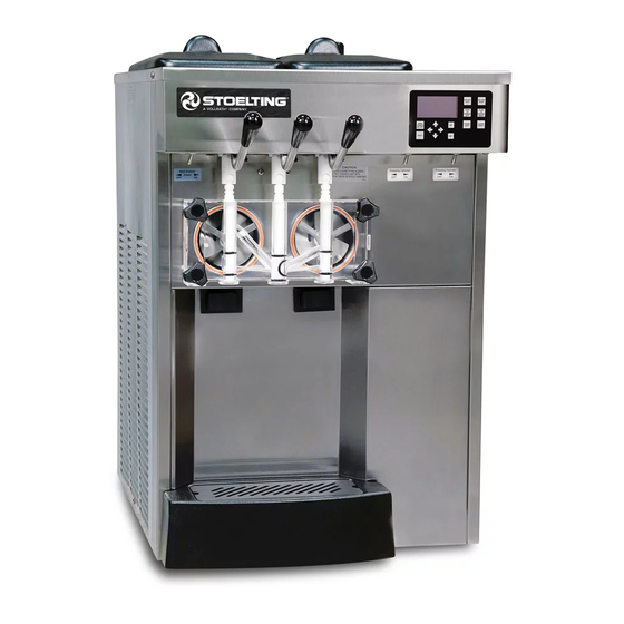
Section 1 - Description and Specifications DESCRIPTION The Stoelting E131-I2 and F131-I2 counter-top machines are gravity fed. The machines are equipped with the IntelliTec2™ control which provides a uniform product. The machines are designed to operate with almost any type of commercial soft serve or non-dairy mixes available, including: ice milk, ice cream, yogurt, and frozen dietary desserts. -
Page 8: Specifications
SPECIFICATIONS Model E131-I2 Dimensions Machine with crate width 22’’ (55,9 cm) 28’’ (71,1 cm) height 34-3/4’’ (88,3 cm) 40-1/4’’ (102,2 cm) depth 28-1/2’’ (72,4 cm) 35-1/4’’ (89,5 cm) Weight 370 lbs (167,8 kg) 450 lbs (204,1 kg) Electrical 1 Phase, 208-240 VAC, 60Hz 3 Phase, 208-240 VAC, 60Hz running amps connection type... -
Page 9: Section 2 - Installation Instructions
Section 2 - Installation Instructions SAFETY PRECAUTIONS A. TOOLS NEEDED • Level Do not attempt to operate the machine until the safety precautions and operating instructions in this manual are • Screwdrivers and wrenches read completely and are thoroughly understood. •... -
Page 10: Intellitec2™ Setup
In air cooled machines correct ventilation is required. 2.4 INTELLITEC2™ SETUP The right side of the machine is the air intake and Disassemble, clean, lubricate and assemble the left side is the discharge. Both sides must have 3” machine following the steps in Section 3. Train store clearance. - Page 11 After the password is accepted, use the arrows to C. SETTING TIME AND DATE move the cursor to the Modify Settings option and Press the right arrow button. press the SEL button. Then move the cursor to the Move the cursor to the Modify Settings option and User Preferences and press the SEL button.
- Page 12 Adjust the product consistency by increasing or decreasing the Consist Offset settings. These settings are under the Modify Settings - Basic Settings menu. Adjust the settings as follows: • If the product is too soft, increase the CutIn Consist Offset. •...
-
Page 13: Section 3 - Initial Set-Up & Installation
Section 3 - Initial Set-Up & Installation OPERATOR’S SAFETY PRECAUTIONS 3.2 OPERATING CONTROLS AND INDICATORS SAFE OPERATION IS NO ACCIDENT; observe these rules: Before operating the machine, it is required that the op- erator know the function of each operating control. Refer Know the machine. -
Page 14: Emptying The Freezing Cylinder
Press the Clean button. After about 5 minutes open the spigot to drain the mix. Press the Clean button to stop the auger. Fill the hopper with 2 gallons (8 liters) of cool tap water. Optional: Use detergent solution instead of tap water to make cleaning the parts easier after disassembly. -
Page 15: Cleaning Disassembled Parts
Remove all o-rings from parts by first wiping off the 3.5 CLEANING DISASSEMBLED PARTS lubricant using a clean towel. Then squeeze the Disassembled parts require complete cleaning, sanitizing o-ring upward to form a loop. Roll the o-ring out of and air drying before assembling. Local and state health the groove. -
Page 16: Sanitizing
NOTICE Install the remaining plastic flights, push the auger into the freezing cylinder and rotate slowly until the The United States Department of Agriculture and auger engages the drive shaft. the Food and Drug Administration require that lubri- cants used on food processing equipment be certi- Apply a thin layer of sanitary lubricant to the inside fied for this use. -
Page 17: Freeze Down And Operation
When sanitizing the machine, refer to local sanitary regula- • Adjustable Carburetor: install with the bend on the tions for applicable codes and recommended sanitizing regulator towards the right. Install the insert and products and procedures. The frequency of sanitizing turn it to the proper flow rate position depending must comply with local health regulations. -
Page 18: Mix Information
The machine dispenses product at a reasonable draw rate. If the machine is overdrawn, the result is a soft product or a product that will not dispense at all. If this occurs, allow the machine to run for approximately 30 seconds before dispensing more product. -
Page 19: Section 4 - Maintenance And Adjustments
Section 4 - Maintenance and Adjustments 4.2 PREVENTATIVE MAINTENANCE This section is intended to provide maintenance personnel with a general understanding of the machine adjustments. It is recommended that a preventative maintenance It is recommended that any adjustments be made by a schedule be followed to keep the machine clean and qualified person. - Page 20 For water-cooled machines that are left in unheated buildings, or buildings subject to freezing, the water must be shut off and disconnected. a. Disconnect the water inlet fitting. The fitting is located at the rear of the machine. b. Press the PUSH TO FREEZE button to run the compressor for 2 - 3 minutes which opens water valve (temporarily place the front door on the machine for the compressor to run).
-
Page 21: Section 5 - Troubleshooting
Section 5 - Troubleshooting ERROR CODES Error Code 3 - Run Time The Run Time Error (E3) occurs when the compressor When the machine experiences a problem, one of the runs continuously for an extended period. This error is following error codes is displayed on the control panel. generally caused by very low mix levels in the hopper or Each error code directs you to the system location of the from product breakdown. - Page 22 Error Code 6 - Hopper Sensor (single hopper machines) Error Code 11 - Prime Error The Hopper Sensor Error (E6) does not occur on this The Prime Error (E11) does not occur on the machine. machine. Error Code 12 - Left Hopper Sensor Error Code 7 - Drive Motor The Left Hopper Sensor Error (E12) indicates a failure of If the control panel displays a Drive Motor Error (E7), the...
-
Page 23: Troubleshooting Machine
5.3 TROUBLESHOOTING MACHINE PROBLEM POSSIBLE CAUSE REMEDY Power to machine is off. Supply power to machine. Machine does not 2 Freeze-up (auger will not turn). 2 Turn machine off for 15 minutes, then restart. run. 3 Front door not in place. 3 Assemble front door in place. - Page 24 Operators Manual #513674 E131-I2 & F131-I2 Model Machines...
-
Page 25: Section 6 - Replacement Parts
Section 6 - Replacement Parts DECALS & LUBRICATION Quantity Part Description E131-I2 F131-I2 C-1000-26C Decal - Made In USA 208135 Brush - 4” x 8” x 16” (Barrel) 208380 Brush - 1/4” x 3” x 14” 208401 Brush - 1” x 3” x 10” 208467 Brush - 3/8”... -
Page 26: Auger & Door
6.2 AUGER & DOOR 381804 381804 666786 666786 482019 482019 694255 694255 149003 149003 2177428 2177428 625133 625133 624678 624678 E131 - 4157952-SV E131 - 4157952-SV F131 - 4157968-SV F131 - 4157968-SV 3170644 3170644 2187811 2187811 2187812 2187812 624614 624614 624598 624598 624664... -
Page 27: Trays & Hopper Cover
6.3 TRAYS & HOPPER COVER 2206054 2149243-01 624677 744262 744271 744260-SV Quantity Part Description E131-I2 F131-I2 417006 Insert - Drip Tray (Vinyl Coated Metal) (YG2 Only) 624677-5 O-Ring - Carburetor Assembly & Spigot Extension - Black (5 Pack) 744260-SV Tray - Drip 744262 Tray - Drain (Black Plastic) (16 1/4”...
Need help?
Do you have a question about the Stoelting E131-I2 and is the answer not in the manual?
Questions and answers
Why is my ice cream not freezing
The Vollrath E131-I2 ice cream machine may not be freezing due to the following reasons:
1. No mix in hopper – Add mix to the hopper.
2. Mix inlet regulator is plugged – Clean the mix inlet regulator.
3. Drive motor overload tripped.
4. Refrigeration problem – Check the system or contact service.
5. Auger is assembled incorrectly – Remove mix, clean, reassemble, sanitize, and freeze down.
6. CutOut Consistency setting is too low – Adjust the CutOut Consistency.
This answer is automatically generated