Table of Contents
Advertisement
Advertisement
Table of Contents
Troubleshooting

Related Manuals for Vollrath Stoelting F231


Summary of Contents for Vollrath Stoelting F231
- Page 1 Model F231 SERVICE MANUAL Manual No. 513659 Rev.2...
- Page 3 This manual provides basic information about the machine. Instructions and suggestions are given covering its operation and care. The illustrations and specifi cations are not binding in detail. We reserve the right to make changes to the machine without notice, and without incurring any obligation to modify or pro- vide new parts for machines built prior to date of change.
- Page 4 A Few Words About Safety Safety Information Safety Alert Symbol: Read and understand the entire manual before This symbol Indicates danger, warning or caution. operating or maintaining Stoelting equipment. Attention is required in order to avoid serious per- sonal injury. The message that follows the symbol This manual provides the operator with information contains important information about safety.
- Page 5 INTELLITEC2™ FIRMWARE VERSION UPDATE LOG The list below shows the history of the fi rmware versions in the IntelliTec2™ control. The information in this manual refers to Version 20.39. VERSION 20.52 Released on 8/22/11 • Motor Calibration screen now returns to the current status screen after pressing the left arrow. •...
- Page 6 VERSION 17.19 Released on 9/8/10 Note: They are few initial machines with 15.19 (8/23/10) where cutout consistency was 70, then pulleys were changed. Two machines with 16.19 had 60 as cutout limit, then some minor internal reset timers were changed and 17.19 released on 9/8/10 •...
-
Page 7: Table Of Contents
TABLE OF CONTENTS Section Description Page Description and Specifi cations Description ....................1 Specifi cations ..................... 2 Installation Instructions Safety Precautions ..................5 Shipment and Transit .................. 5 Machine Installation ..................5 Installing Permanent Wiring ................ 5 Initial Startup of IntelliTec2™ ..............6 Initial Set-Up and Operation Operator’s Safety Precautions .............. - Page 8 Section Description Page Refrigeration System Refrigeration System .................. 27 Refrigerant Recovery and Evacuation ............27 Refrigerant Charging .................. 28 Compressor ....................29 Condenser ....................30 Valves ......................30 Thermostatic Expansion Valve (TXV) ..............30 Automatic Expansion Valve (AXV) ............... 31 Check Valve ......................
-
Page 9: Description
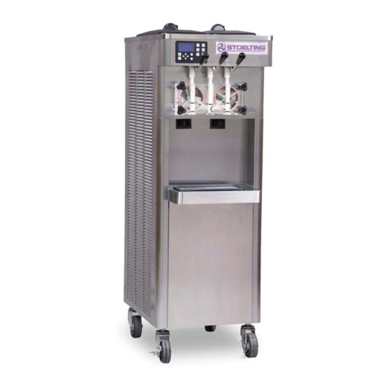
SECTION 1 INTRODUCTION 1.1 DESCRIPTION The Stoelting F231 fl oor machine is gravity fed. The machine is equipped with the IntelliTec2™ control which provides a uniform product. The F231 is designed to operate with almost any type of commercial soft serve or non-dairy mixes available, including: ice milk, ice cream, yogurt, and frozen dietary desserts. -
Page 10: Specifications
SPECIFICATIONS Figure 1-2 Dimension Specifi cations (variations on spigot handles and casters available) Model F231 Dimensions Machine as shipped width 19-1/4’’ (48,9 cm) 32’’ (81,3 cm) height 58-1/4’’ (148,0 cm) 60’’ (152,4 cm) depth 28’’ (71,1 cm) 39’’ (99,1 cm) 400 lbs (181,4 kg) 470 lbs (213,1 kg) Weight... - Page 11 Menu Display F231 Enable Control Consistency/Consistency Basic CutOut Consist Offset CutIn Consist Offset CutIn Temp 19.5 °F CutOut Temperature 19 °F Cycles In Serve Mode Standby On Time 10 sec Advanced Standby Off Time 360 sec Standby Time 120 min Stir On 15 sec Stir Off...
- Page 12 Service Manual #513659 Model F231...
-
Page 13: Installation Instructions
SECTION 2 INSTALLATION INSTRUCTIONS Uncrate the machine. 2.1 SAFETY PRECAUTIONS Install the four casters. Turn the threaded end Do not attempt to operate the machine until the safety into the machine until no threads are showing. To precautions and operating instructions in this manual are level, turn out casters no more than 1/4”... -
Page 14: Initial Startup Of Intellitec2
The screen will change and show “File Found” for 2.5 INITIAL STARTUP OF INTELLITEC2™ a quick second while it updates the information. Before completing the following procedures, follow the After updating the contact information, the screen steps in Section 3 to disassemble, clean, lubricate and will show the Service Contact Information page. - Page 15 Press the left arrow button to go back to the Current Status screen. Then press the right arrow to go to the Main Menu. NOTE If you press the left arrow from the Current Status screen it will ask for the password. Press the right arrow, SET, then the SEL button.
- Page 16 Service Manual #513659 Model F231...
-
Page 17: Initial Set-Up And Operation
SECTION 3 INITIAL SET-UP AND OPERATION 3.1 OPERATOR’S SAFETY PRECAUTIONS 3.2 OPERATING CONTROLS AND INDICATORS SAFE OPERATION IS NO ACCIDENT; observe these Before operating the machine, it is required that the op- rules: erator know the function of each operating control. Refer to Figure 3-1 for the location of the operating controls on Know the machine. -
Page 18: Disassembly Of Machine Parts
3.3 DISASSEMBLY OF MACHINE PARTS Before using the machine for the fi rst time, complete machine disassembly, cleaning and sanitizing proce- dures need to be followed. Routine cleaning intervals and procedures must comply with the local and state health codes. Inspection for worn or broken parts should be made at every disassembly of the machine. -
Page 19: Cleaning Disassembled Parts
B. DISASSEMBLY OF FRONT DOOR 3.4 CLEANING DISASSEMBLED PARTS Turn the machine off by pressing the Main Freezer Disassembled machine parts require complete cleaning, Power Off/On button on the IntelliTec2™ control. sanitizing and air drying before assembling. Local and state health codes will dictate the procedure required. -
Page 20: Assembling The Machine
Using sanitizing solution and the large barrel Lubricate the hex drive end of the auger with a brush provided, sanitize the freezing cylinder by small amount of spline lubricant. A small container dipping the brush in the sanitizing solution and of spline lubricant is shipped with the machine. -
Page 21: Freeze Down And Operation
Prepare 2 gallons of Stera-Sheen sanitizing When the product is at 75% consistency, the solution following the manufacturer’s instructions. display will read “SERVE”. Open the spigot to dispense product. Install the mix inlet regulator into the hopper. The machine dispenses product at a reasonable Pour the sanitizing solution into the hopper. -
Page 22: Mix Information
3.11 MIX INFORMATION Mix can vary considerably from one manufacturer to another. Differences in the amount of butterfat content and quantity and quality of other ingredients have a direct bearing on the fi nished frozen product. A change in machine performance that cannot be explained by a technical problem may be related to the mix. -
Page 23: Maintenance And Adjustments
SECTION 4 MAINTENANCE AND ADJUSTMENTS This section is intended to provide maintenance personnel The Current Status screen gives an overview of the with a general understanding of the machine adjustments. machine's operation. It shows the mode of the freezing It is recommended that any adjustments in this section cylinders and the storage refrigeration. -
Page 24: Performance Screens
D. Fine Consistency Adjustment B. Performance (2 of 2) Fine Consistency Adjustment Performance (2 of 2) Cylinder Right Cylinder Right Changing the fine consistency change the firmness of the Ambient Temp -000.0°F product. Storage Temp -000.0°F Consistency CutIn Limit Number of Cycles Consistency CutOut Limit _ Fine Consistency Error Status... - Page 25 Cylinder can be changed by pressing the SEL button. D. Advanced Settings (2 of 2) The Enable Control setting determines the cutin and cutout style. The options are Consistency-Consistency, Advanced Settings (2 of 2) Temperature-Consistency or Temperature-Temperature. Cylinder Right Setting the control to Consistency-Consistency enables _ Sleep 2 CutIn -00.0°F Serve 2 Mode (instead of Serve 1 Mode).
-
Page 26: Utilities Screens
F. Storage Settings (2 of 2) H. Time and Date Storage Settings (2 of 2) Time and Date _ Storage Max On 00 min Time 00:00:00 AM _ Storage Recovery 0 min Date 00/00/00 _ Storage Too Warm 00.0°F Daylight Savings _ Storage Too Warm 000 min Clock Type... - Page 27 The Product Selection screen changes CutIn Consis- E. Clean Options tency and CutOut Consistency to a predetermined value depending on the product type. Clean Options B. Adjust LCD Contrast Clean History Log Clean Warning Adjust LCD Contrast Clean Lockout 0123456789 ABCDEFGHIJKLMNOPQRSTUVWXYZ Press to change...
- Page 28 F. Testing and Manual Operation Test Monitoring (1 of 3) Testing and Manual Operation Cylinder Right Select below for testing CRC Errors Dis/IO 0/6791 Motor Voltage 0.0 V _ Left Output Control Motor Current 0.000 _ Right Output Control I/V Phase Angle 0.0°...
-
Page 29: Errors & Statistics Screens
I. Clear Log Data K. Restore Unit Confi guration Reset Unit Configuration Clear Log Data This will reset the unit type This will clear the error log and motor types. and the statistics. Are you sure Are you sure you want to do that you want to do that _ No _ No... - Page 30 B. Machine Statistics (2 of 10) E. Machine Statistics (5 of 10) Machine Statistics (5 of 10) Machine Statistics (2 of 10) Cylinder Right Cylinder Right Estimated Serve Amount 0000 gal Total Low Mix Run 0000 hr Last 24hrs 0000 gal Last 24hrs 0000 min Last 7days...
-
Page 31: Updating Firmware
H. Machine Statistics (8 of 10) K. Error History Error History 25 of 25 Machine Statistics (8 of 10) Type Cylinder Sensor Cylinder Right Date 00/00/00 00:00:00 AM Pump Run Time 0000 hr Cylinder Right Pump Cycles 0000 _ Status At Time of Error Last Pump Reset 00/00/00 _ Help... -
Page 32: Drive Belt Tension Adjustment
Connect the USB fl ash drive to the port on the Go to the Motor Zero Load Calibration option and machine. Depending on the model, the USB port press the SEL button. will be located: NOTE 1. On the side of the machine. Remove the plug. Calibration must be done with water or liquid mix 2. -
Page 33: Condenser Cleaning
Remove the back panel. 4.11 PREVENTATIVE MAINTENANCE Use a Burroughs Belt Tension Gauge to set the It is recommended that a preventative maintenance tension for the drive belt. Set the belt tension to schedule be followed to keep the machine clean and 40-45 lbs. - Page 34 Service Manual #513659 Model F231...
-
Page 35: Refrigeration System
SECTION 5 REFRIGERATION SYSTEM 5.1 REFRIGERATION SYSTEM NOTE The F231 refrigeration systems have two functions: For qualifi ed service personnel only. Anybody work- ing with refrigerants must be certifi ed as a Techni- Medium-Temperature - Maintaining mix cian TYPE I as required by 40 CFR 82 Subpart F temperature in the hopper. -
Page 36: Refrigerant Charging
Evacuate the system until the gauge reads 300 A. REFRIGERANT RECOVERY microns of mercury (300μ Hg) for 5 continuous Disconnect the machine from electrical supply minutes. before removing any panels for servicing. If the system will not maintain a standing vacuum Remove all panels. -
Page 37: Compressor
To check if windings are shorted to ground, connect 5.4 COMPRESSOR one ohmmeter lead to a bare metal part on the The F231 has a hermetic reciprocating compressor (Refer compressor (such as any copper line leading to to Figure 5-2). or from the compressor) and check terminals C, R, and S. -
Page 38: Condenser
Remove all tubing plugs from the replacement TXV TESTING & ADJUSTMENT compressor. NOTE NOTE The bulb has an indent which must be positioned The compressor plugs protect the compressor from against the tubing. Good contact between the moisture in the air. Do not remove the plugs until bulb and the suction line is necessary for proper you are ready to install. -
Page 39: Automatic Expansion Valve (Axv)
Immediately before the refrigeration cycle ends, TXV REPLACEMENT the gauge should read the following: To replace the TXV, perform the following procedures: OT2 Models: 22-24 psig Position the TXV, with a heat sink, into the system. YG2 Models: 23-25 psig With the suction and discharge ports open, braze the TXV into the system. -
Page 40: Check Valve
High pressure cutout should trip when pressure C. CHECK VALVE reaches 445 psig ±9. The machine has 3 magnetic check valves (Refer to Figure 5-6). Each valve is positioned in the suction line HIGH PRESSURE CUTOUT REMOVAL and prevents backfl ow of refrigerant into the evapora- Remove the left side panel. -
Page 41: Evaporator Pressure Regulator (Epr)
HOT GAS BYPASS ADJUSTMENT F. EVAPORATOR PRESSURE REGULATOR (EPR) Adjustment to the hot gas bypass must be made when the There is one EPR in the refrigeration system (Refer to hopper refrigeration is the only part of the system running. Figure 5-9). -
Page 42: Water Valve (Water Cooled Models Only)
G. WATER VALVE (WATER COOLED MODELS ONLY) WATER VALVE REPLACEMENT The water valve monitors refrigerant pressure and opens To replace the water valve, perform the following proce- on an increase of pressure. The opening point pressure dures: is the refrigerant pressure required to lift the valve disc Position the water valve and attach to the frame off the valve seat. - Page 43 Turn the machine on by pressing the Main Power ACTIVATING A SOLENOID Off/On button. To open a solenoid, follow these steps: Press the right arrow, SET, then the SEL button Turn the machine on by pressing the Main Power to access the technician level on the control. Off/On button.
-
Page 44: Filter Drier
Apply a heat sink (wet cloth) to the solenoid valve. 5.9 CAPILLARY TUBE With the suction and discharge ports open, braze The capillary tube meters refrigerant fl ow in the mix line the solenoid into the system. evaporator (Refer to Figure 5-14). The amount of fl ow is dependent on the length and ID of the capillary tube as Remove the heat sink from the valve. -
Page 45: Electrical And Mechanical Control Systems
SECTION 6 ELECTRICAL AND MECHANICAL CONTROL SYSTEMS NOTE The wiring diagram is available in Section 8. INTELLITEC2™ CONTROL The IntelliTec2™ control consists of three main compo- nents; a control board, a display board and a membrane switch (touchpad). The control board is modular and consists of a program board and a relay board. -
Page 46: Drive Motor
DRIVE MOTOR The F231 has two drive motors. They are used to rotate the auger assemblies. An internal, normally closed, cen- trifugal switch starts the drive motor. The motors have an internal thermal overload. A. DRIVE MOTOR TEST Turn the machine off by pressing the Main Power Off/On button and disconnect the machine from the electrical supply. -
Page 47: Capacitors
Pull the capacitor out of its holder and replace. CAPACITORS Connect the leads to the terminals of the new The compressor start and run capacitors are only on single capacitor. phase machines. They are accessible by removing the right side panel. GEARBOX The start and run capacitors for the drive motors are mounted directly onto each motor body. -
Page 48: Spigot Switch
Spigot Glide Figure 6-5 Spigot Cam Assembly (Center Spigot) Figure 6-4 Air Cooled Condenser Open the spigot slowly and listen for a click when the spigot switch closes. B. FAN MOTOR INSTALLATION The clicking sound should be within the fi rst 1/2” Attach motor to the mounting plate with the three of the spigot glide movement (Refer to Figure bolts. -
Page 49: Temperature Control Sensor
TEMPERATURE CONTROL SENSOR The temperature control sensor is a thermistor used to sense the temperature of the suction line. As the suction line temperature increases, the internal resistance of the thermistor will decrease. Refer to Figure 6-7 for the relationship between sensor resistance and temperature. The IntelliTec control board monitors this value. - Page 50 Service Manual #513659 Model F231...
-
Page 51: Troubleshooting
SECTION 7 TROUBLESHOOTING Ice crystals in the hopper can clog the mix 7.1 ERROR CODES inlet regulator and prevent mix from entering When the machine experiences a problem, one of the the freezing cylinder. Thoroughly thaw mix per following error codes will be displayed on the control manufacturer's recommendations. - Page 52 ERROR CODE 5 - FREEZING CYLINDER SENSOR ERROR CODE 6 - HOPPER SENSOR The Freezing Cylinder Sensor Error (E5) indicates The Hopper Sensor Error (E6) will not occur on a failure of the barrel sensor or if the sensor is the F231.
- Page 53 ERROR CODE 11 - PRIME ERROR CODE 21 - SPIGOT OPEN TIME The Prime Error (E11) will not occur on the F231. The Spigot Open Time Error (E21) indicates a failure of the spigot switch. If the control senses ERROR CODE 12 - LEFT HOPPER SENSOR the spigot is open continuously for 10 minutes, the The Left Hopper Sensor Error (E12) indicates machine will go into Sleep 3 mode.
-
Page 54: Troubleshooting - Machine
7.3 TROUBLESHOOTING - MACHINE PROBLEM POSSIBLE CAUSE REMEDY 1 Power to machine is off. 1 Supply power to machine. Machine does not run. 2 Front door not in place. 2 Assemble front door in place. 1 Drive belt failure. 1 Replace drive belt. 2 Consistency temperature setting is too 2 Adjust the CutOut Consistency Offset (See Machine will not... -
Page 55: Replacement Parts
SECTION 8 REPLACEMENT PARTS 8.1 DECALS, LUBRICATION AND MISCELLANEOUS Part Description Quantity 208135 Brush - 4” X 8” X 16” (Barrel) 208380 Brush - 1/4” X 3” X 14” 208401 Brush - 1” X 3” X 10” 208467 Brush - 3/8” X 1” X 5” 229158 USB Cable Extension 236059... -
Page 56: Auger Shaft And Faceplate Parts
8.3 AUGER SHAFT AND FACEPLATE PARTS 694255 381804 149003 666786 624678-5 4157968 3170644 625133 2149241 2149243-01 2177428 624677-5 2187812 2187811 624598-5 624664-5 624614-5 744262 417006 744273 Service Manual #513659 Model F231... -
Page 57: Air Plenum Kit
8.3 AUGER SHAFT AND FACEPLATE PARTS (CONTINUED) Part Description Quantity 149003 Bushing - Front Auger Support 232734 Cap - Rosette 314453 Cover - Hopper 381804 Auger Flight 417006 Grid - Drip Tray ( Vinyl Coated Metal) 482019 Knob - Front Door (Black) 624598-5 O-Ring - Outside Spigot - Black (5 Pack) 624614-5... -
Page 58: Internal Components
8.5 INTERNAL COMPONENTS 2202316 231078 762454 762490 763422 763482 231095 272065 342004 763423 521513 618142 521514 618157 521516 763017 231084 614237 230649 231079 598032 718794 493115 624717 231107 295112 762978 152234 598540 342020 522858-SV 522859 458003 523345 284084 282032-SV 282033-SV 162077 282050-SV 522291... - Page 59 8.5 INTERNAL COMPONENTS (CONTINUED) Part Description Quantity 152231 Belt - Gripnotch (AX32) (1 per Side) (Ser. #0 - #33842) 152234 Belt - Gripnotch (AX33) (1 per Side) (Ser. #33725, #33737, #33739 & #33843 Plus) 162077 Blade - Fan (Air-Cooled Condenser) 229148 Cable - IntelliTec2™...
-
Page 60: Spigot Assembly
8.6 SPIGOT ASSEMBLY 718773 696044 570961 2158082 428045 2187805 Part Description Quantity 428045 Knob - Spigot Handle (Black) 570961 Pin - Cotterless Clevis (Spigot Cam) 696044 Spring - Torsion (Spigot Cam) 718773 Switch - Limit (Spigot Cam) 2158082 Glide - Spigot Socket 2187805 Handle - Spigot (Handle Only) 8.7 FRONT... -
Page 61: Wiring Diagrams
8.8 WIRING DIAGRAMS Service Manual #513659 Model F231... - Page 62 Service Manual #513659 Model F231...
- Page 63 DOMESTIC WARRANTY (Including Mexico) SOFT SERVE / SHAKE EQUIPMENT 1. Scope: PW Stoelting, L.L.C. (“Stoelting”) warrants to the first user (the “Buyer”) that the freezing cylinders, hoppers, compressors, drive motors, speed reducers, and augers of Stoelting soft serve / shake equipment will be free from defects in materials and workmanship under normal use and proper maintenance appearing within five (5) years, and that all other components of such equipment manufactured by Stoelting will be free from defects in material and workmanship under normal use...
Need help?
Do you have a question about the Stoelting F231 and is the answer not in the manual?
Questions and answers