Table of Contents
Advertisement
Quick Links
Advertisement
Table of Contents
Troubleshooting

Related Manuals for Vollrath STOELTING U421-I2A


Summary of Contents for Vollrath STOELTING U421-I2A
- Page 1 Model U421-I2A & U431-I2A SERVICE MANUAL Manual No. 513721 Rev.0...
- Page 3 This manual provides basic information about the machine. Instructions and suggestions are given covering its operation and care. The illustrations and specifi cations are not binding in detail. We reserve the right to make changes to the machine without notice, and without incurring any obligation to modify or pro- vide new parts for machines built prior to date of change.
- Page 4 A Few Words About Safety Safety Information Safety Alert Symbol: Read and understand the entire manual before This symbol Indicates danger, warning or caution. operating or maintaining Stoelting equipment. Attention is required in order to avoid serious per- sonal injury. The message that follows the symbol This manual provides the operator with information contains important information about safety.
-
Page 5: Table Of Contents
TABLE OF CONTENTS Section Description Page Introduction Description ....................1 Specifi cations ..................... 2 Component Settings ................... 4 Refrigeration System Refrigeration System .................. 5 Refrigerant Recovery and Evacuation ............6 Refrigerant Charging .................. 6 Compressor ....................6 Condenser ....................8 Valves ...................... - Page 6 Section Description Page Replacement Parts Brushes, Decals, and Lubrication ............... 23 Auger Shaft and Door Parts ............... 24 Cab Tubing ....................25 Trays ......................26 Panels & Screws ..................26 Cabinet ....................... 27 Cabinet Evaporator ..................28 Pump Parts ....................29 Spigots ......................
-
Page 7: Description
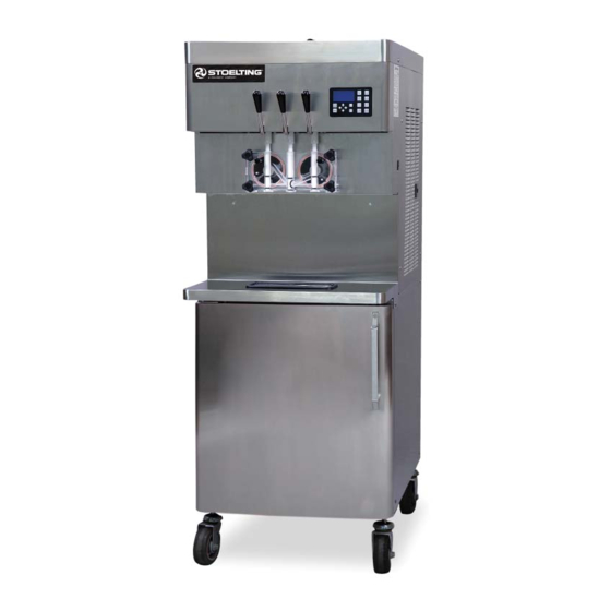
SECTION 1 DESCRIPTION AND SPECIFICATIONS DESCRIPTION The Stoelting U421-I2A and U431-I2A fl oor model ma- chines are pressure fed. They are equipped with fully automatic controls to provide a uniform product. This manual is designed to assist qualifi ed service per- sonnel with troubleshooting and repairing the U421-I2A and the U431-I2A. -
Page 8: Specifications
SPECIFICATIONS Air Cooled Air Cooled Remote Water Cooled U421-I2A & U431-I2A U421-I2A & U431-I2A U421-I2A & U431-I2A Dimensions Machine with crate Machine with crate Machine with crate 26-3/4’’ 34’’ 26-3/4’’ 34’’ 26-3/4’’ 34’’ width (67,9 cm) (86,4 cm) (67,9 cm) (86,4 cm) (67,9 cm) (86,4 cm) - Page 9 Menu Display U421 I2A & U431 I2A Enable Control Temp/Temp Basic CutOut Consist Offset CutIn Consist Offset CutIn Temp 40 °F CutOut Temperature 12 °F Cycles In Serve Mode Standby On Time 10 sec Advanced Standby Off Time 360 sec Standby Time 120 min Stir On...
-
Page 10: Component Settings
COMPONENT SETTINGS D. TEMPERATURE CONTROL SENSOR The following table shows the relationship between the Following are the settings for the components in the thermistor resistance and the suction line temperature. U421-I2A and U431-I2A machines. A. COMPRESSOR WINDINGS °F Resistance °F Resistance When testing the compressor windings the resistance 176950... -
Page 11: Refrigeration System
SECTION 2 REFRIGERATION SYSTEM 2.1 REFRIGERATION SYSTEM The U421-I2A and U431-I2A have three separate refrigeration systems; one for each freezing cylinder and one for the cabinet. The freezing cylinder systems are designed for use with R404A refrigerant and the cabinet system is designed for use with R134A refrigerant. -
Page 12: Refrigerant Recovery And Evacuation
2.2 REFRIGERANT RECOVERY AND 2.3 REFRIGERANT CHARGING EVACUATION Refer to the following procedures to properly charge the refrigeration system. Stoelting recommends liquid Refer to the following procedures to properly recover and refrigerant charging. evacuate the refrigeration system. Do not purge refriger- ant into the atmosphere. - Page 13 Leave the suction and discharge ports open to prevent pressure buildup during compressor removal. Remove six inches of insulating tubing on the suction line going to the compressor and unsweat the suction and discharge line from the compressor. Cap or plug the refrigeration system if the compressor will not be replaced immediately (within 10 minutes) to prevent contamination.
-
Page 14: Condenser
Immediately before the refrigeration cycle ends, 2.5 CONDENSER the gauge should read between 19-21 psig. The The U421-I2A and U431-I2A are available with either an superheat should be 7-10°F. air-cooled, water-cooled, or air cooled remote condenser. If the pressure reading is higher than expected The capacity of the machine is directly related to keeping and the superheat is low, check to see if there is the condenser clean and free of debris. -
Page 15: Check Valve
TXV REPLACEMENT C. HIGH PRESSURE CUTOUT To replace the TXV, perform the following procedures: There is a high pressure cutout for each freezing cylinder (Fig 2-7) and one for the cabinet refrigeration (Fig 2-8). Position the TXV with a heat sink into the system. The high pressure cutout stops the compressor if the With the suction and discharge ports open, braze discharge pressure reaches the cutout, 445 psig for the... -
Page 16: Evaporator Pressure Regulator (Epr)
High pressure cutout should trip when pressure Connect power to the machine. reaches 445 psig ±9 in the freezing cylinder Turn the machine on by pressing the Main Power system and 405 psig in the cabinet system. Off/On button. Listen for the cabinet compressor to start. -
Page 17: Solenoid (Air Cooled Remote Only)
Replace the fi lter drier. Refer to Section 2.8 for WATER VALVE ADJUSTMENT details. Remove the lower front panel and side panel. Evacuate and recharge system per instructions Connect a gauge to the compressor discharge in Section 2.2. Schrader valve. Turn on the water and check for leaks in the water Connect the machine to the electrical supply, start lines with the refrigeration system running. -
Page 18: Filter Drier
Navigate to the Left Output Control or Right Output With the suction and discharge ports open, braze Control menu which is located under Utilities in the solenoid into the system. the Testing and Manual Operation screen. Refer Remove the heat sink from the valve. to Section 4 for details. -
Page 19: Electrical And Mechanical Control Systems
SECTION 3 ELECTRICAL AND MECHANICAL CONTROL SYSTEMS NOTE A. DRIVE MOTOR TEST Turn the machine off by pressing the Main Power The wiring diagram is available in Section 5. Off/On button and disconnect the machine from the electrical supply. 3.1 INTELLITEC2 CONTROL The IntelliTec2 control consists of three main components;... -
Page 20: Capacitors
Go to the Test Monitoring screen under Utilities. Remove the motor mounting nuts and remove The motor current should be as follows: the motor. Single Phase Machines: 6.1-6.3 Amps Loosen the two allen head screws from the pulley. Three Phase Machines: 4.0-4.2 Amps Remove the pulley and key from the motor shaft. -
Page 21: Gearbox
Disconnect the bleeder resistor from the circuit. C. GEARBOX INSTALLATION Measure the capacitance across the terminals. Place the gearbox in position from the rear of the The results should be as follows: machine. Fasten the bolts through the gearbox to the rear of the barrel. Mount the pulley on the gearbox shaft and align Rating with the motor pulley, then tighten the allen head... -
Page 22: Cab Condenser Fan Motor
Install fan shroud into cab with the four screws. C. FAN MOTOR INSTALLATION Rotate the fan motor so the mounting holes are Install evaporator cover with the two thumb screws. lined up with the holes in the fan guard. Install all tubes and replace the drawers. Install the fan to the fan guard using the torx screws. -
Page 23: Pump Pressure Switch
Remove the two Phillips head screws that attach SPIGOT SWITCH TESTING - ELECTRICAL the spigot cam assembly to the panel. Remove Disconnect the switch from the circuit by the assembly. unplugging the connectors. Disconnect the connector from the switch and Check resistance readings across the common remove the switch.. -
Page 24: Temperature Control Sensor
3.9 TEMPERATURE CONTROL SENSOR °F Resistance °F Resistance The temperature control sensor is a thermistor used to 176950 26100 sense the temperature of the suction line. As the suc- 165200 24725 tion line temperature increases, the internal resistance of the thermistor decreases. Refer to Figure 3-8 for the 154300 23400 relationship between sensor resistance and temperature. -
Page 25: Troubleshooting
SECTION 4 TROUBLESHOOTING 4.1 ERROR CODES ERROR CODE 3 - RUN TIME The Run Time Error (E3) occurs when the control When the machine experiences a problem, one of the senses that the compressor is not operating following error codes is displayed on the control panel. properly. - Page 26 ERROR CODE 5 - FREEZING CYLINDER SENSOR ERROR CODE 6 - HOPPER SENSOR The Freezing Cylinder Sensor Error (E5) indicates The Hopper Sensor Error (E6) will not occur on a failure of the barrel sensor or a sensor that the U421-I2A or U431-I2A. is out of range.
- Page 27 ERROR CODE 10 - AMBIENT SENSOR ERROR CODE 16 - ROTATE HOSE The Ambient Temperature Sensor Error (E10) The Rotate Hose Error (E16) occurs when the indicates a failure of the condenser air inlet Hose Service Limit has been met. temperature sensor or if the sensor is out of Rotate or replace the pump hose and reset the range.
-
Page 28: Troubleshooting - Machine
4.3 TROUBLESHOOTING - MACHINE PROBLEM POSSIBLE CAUSE REMEDY 1 Power to machine is off. 1 Supply power to machine. Machine does not 2 Freeze-up (auger will not turn). 2 Turn machine off for 15 minutes, then restart. run. 3 Front door not in place. 3 Assemble front door in place. -
Page 29: Replacement Parts
SECTION 5 REPLACEMENT PARTS BRUSHES, DECALS, AND LUBRICATION Quantity Part Description U421 U431 C-1000-26C Decal - Made In USA 208135 Brush - 4” X 8” X 16” (Barrel) 208380 Brush - 1/4” X 3” X 14” 208387 Brush - 1/2” X 5” X 24” 208465 Brush - 1”... -
Page 30: Auger Shaft And Door Parts
AUGER SHAFT AND DOOR PARTS 2177427 2177427 2110116 2110116 2187696 2187696 2183106 2183106 694200 694200 624520 624520 624520 624520 694200 694200 482004 482004 482019 482019 482004 482004 482019 482019 3159696 3159696 2204252 2204252 624664 624664 624598 624598 624598 624598 624614 624614 U431-I2A U421-I2A... -
Page 31: Cab Tubing
CAB TUBING 756088 756088 2206787 2206787 264235 264235 2206611 2206611 2206610 2206610 264241 264241 2208043 2208043 624644 624644 234235 234235 756236 756236 624616 624616 2208137 2208137 694247 694247 2208193-SV 2208193-SV 2206609 2206609 762256 762256 2206608 2206608 2208169 2208169 232024 232024 264235 264235 264235... -
Page 32: Trays
TRAYS 417006 417006 744273 744273 744610 744610 744630 744630 417010 417010 744287 744287 Quantity Part Number Description U421 U431 417006 Insert - Drip Tray (Vinyl Coated Metal) 417010 Insert - Drip Tray 744273 Tray - Drip 744287 Tray - Drip (Black) 744610 Tray - Drain w/Magnet (Ser. -
Page 33: Cabinet
CABINET 571031 571031 653022 653022 396464 396464 128311 128311 2208167 2208167 2208030 2208030 653022 653022 128330-SV 128330-SV 428094 428094 2206948 2206948 428093 428093 2205332 2205332 2208046 2208046 2206887 2206887 Quantity Part Description U421 U431 128311 Hinge - Door (Top & Bottom) (Cab) 128330-SV Bearing Assembly (Bearing &... -
Page 34: Cabinet Evaporator
CABINET EVAPORATOR 719123-SV 719123-SV 2208057 2208057 736084 736084 2208068 2208068 2208265 2208265 264243 264243 2208067 2208067 Quantity Part Description U421 U431 162053 Blade - Fan (#355005 Evaporator) (Cab) 264243 Clamp - Metal (3/8” ID Tubing) (Cab) 266090 Clip - LED Light Strip 355005 Evaporator (Angled) 493000... -
Page 35: Pump Parts
PUMP PARTS 1177037 1177034 1171864 1171958 1171863 1171862 1177035 1171860 1171861-SV 1177036 1171866 432003-SV 1171987 653042 1171986 644065 1171868 3171952 1171874 1171867 2177812 1171985-SV 1171870 1177681 1171981 1171986 1171866 1171984 1171983 1171955 1171982 1171991 2208228 1171956 1171979 1171990 128283 1171978 652412 650146 1171871... - Page 36 PUMP PARTS (CONTINUED) Quantity Part Number Description U431 U421 128283 Crank Arm Roller Assy (Requires #652412) (Cab) 432003-SV Valve Head Only w/Tubes (Pump) (Cab) 522229 Motor - Pump (w/Capacitor) (Cab) 538306 Nut - Motor Mounting (Cab) 644065 Screw - Rocker Arm (Cab) 650146 Set Screw - Pulley (Cab) 652412...
-
Page 37: Spigots
SPIGOTS Pull-Down Style Swing Gate Style 2158082 2158082 694247 694247 718773 718773 718773 718773 3154601 3154601 482004 482004 694247 694247 570961 570961 221619 221619 2203282 2203282 2156997 2156997 2156999 2156999 482039 482039 2157850 2157850 428045 428045 1154703 1154703 696044 696044 625440 625440 2187805... -
Page 38: Electrical
5.10 ELECTRICAL Header Panel 521516 521516 521514 521514 332563-SV 332563-SV 295017 295017 521513 521513 618271 618271 719127-SV 719127-SV 732374 732374 593093 593093 718537 718537 2203058 2203058 Electrical Box 618180 618180 230638 230638 231047 231047 Quantity Part Description U421 U431 229148 Cable - IntelliTec2 (Control Board to Display Board) 229158 USB Cable Extension... -
Page 39: Motor
5.11 MOTOR 2147034 2147034 614220 614220 152297 152297 522325 522325 522851 522851 522856-SV 522856-SV 522869 522869 2117987 2117987 Quantity Part Description U421 U431 152297 Belt - Smooth (A37KC) (50/60 Hz) 230622 Capacitor - Start (#522856 Motor) 231075 Capacitor - Run (#522856 Motor) 522324 Motor - Drive (3 PH, 60 HZ) (Internal Overload) 522851... -
Page 40: Cabinet Condensing Unit
5.12 CABINET CONDENSING UNIT 162044 162044 423043 423043 284049 284049 522295 522295 230667 230667 618365 618365 368448 Quantity Part Number Description U421 U431 162044 Blade - Fan (#285073 Condensing Unit) (Cab) 230667 Capacitor - Start (#285073 Condensing Unit) (Cab) 231101 Cap Tube Only (Mix Line) (Cab) 231108 Cap Tube Only (Cab) -
Page 41: Side View
5.13 SIDE VIEW 357102 357102 202235 202235 743654 743654 718539 718539 295112 295283 342008 342008 230654 230654 762412 762412 2206952 2208135 375813 375813 2208143 2208144 762978 762978 231101 231101 458009 458009 231108 231108 DR-0010 DR-0010 718794 718794 282106 282107 282108 Service Manual #513721 U421-I2A &... -
Page 42: Air-Cooled Remote Condensers
5.13 SIDE VIEW (CONTINUED) Qty (per unit) Part Description U421 U431 DR-0010 Drier - Filter (1/4” OD) (Cab Condenser) 202235 Circuit Breaker 230654 Capacitor (Fan Motor) 231101 Cap Tube Only (Mix Line) (Cab) 231108 Cap Tube Only (Cab) 266165 Clip - Thermistor (#672798) 282106 Compressor - 1 PH - 60 Hz 282107... -
Page 43: Kits And Miscellaneous
5.15 KITS AND MISCELLANEOUS Quantity Part Number Description U421 U431 236067 Card - Cleaning Instruction 244138 Caster - Non-Locking (4”) (Each) 244139 Caster - Locking (4”) (Each) 624677-5 O-Ring - Spigot Extension - Black (5 Pack) 1172867 Check Valve Kit - Mix Line (Cab) 1177436 Air Compressor Kit (Includes Piston &... - Page 44 Service Manual #513721 U421-I2A & U431-I2A Model Machines...
-
Page 45: Refrigeration Diagram And Wiring Diagrams
SECTION 6 REFRIGERATION DIAGRAM AND WIRING DIAGRAMS REFRIGERATION DIAGRAMS Cabinet Refrigeration System Water Cooled Refrigeration System (One Side Shown) Remote Air Cooled Refrigeration System (One Side Shown) Service Manual #513721 U421-I2A & U431-I2A Model Machines... -
Page 46: Wiring Diagrams
WIRING DIAGRAMS Service Manual #513721 U421-I2A & U431-I2A Model Machines... -
Page 47: U421-409I2A
Service Manual #513721 U421-I2A & U431-I2A Model Machines... -
Page 48: U421-109I2A
Service Manual #513721 U421-I2A & U431-I2A Model Machines... -
Page 49: U431-48I2A
Service Manual #513721 U421-I2A & U431-I2A Model Machines... -
Page 50: U431-38I2A
Service Manual #513721 U421-I2A & U431-I2A Model Machines... -
Page 51: U431-18I2A
Service Manual #513721 U421-I2A & U431-I2A Model Machines... -
Page 52: U431-409I2A
Service Manual #513721 U421-I2A & U431-I2A Model Machines... -
Page 53: U431-309I2A
Service Manual #513721 U421-I2A & U431-I2A Model Machines... -
Page 54: U431-109I2A
Service Manual #513721 U421-I2A & U431-I2A Model Machines...
Need help?
Do you have a question about the STOELTING U421-I2A and is the answer not in the manual?
Questions and answers