Table of Contents
Advertisement
Quick Links
Advertisement
Table of Contents

Related Manuals for Vollrath STOELTING E122


Summary of Contents for Vollrath STOELTING E122
- Page 1 Model E122 & F122 SERVICE MANUAL Manual No. 513668 Rev.0...
- Page 3 This manual provides basic information about the machine. Instructions and suggestions are given covering its operation and care. The illustrations and specifi cations are not binding in detail. We reserve the right to make changes to the machine without notice, and without incurring any obligation to modify or pro- vide new parts for machines built prior to date of change.
- Page 4 A Few Words About Safety Safety Information Safety Alert Symbol: Read and understand the entire manual before This symbol Indicates danger, warning or caution. operating or maintaining Stoelting equipment. Attention is required in order to avoid serious per- sonal injury. The message that follows the symbol This manual provides the operator with information contains important information about safety.
-
Page 5: Table Of Contents
TABLE OF CONTENTS Section Description Page Description and Specifi cations Description ....................1 Specifi cations ..................... 2 Component Settings ................... 4 Modes of Normal Operation ............... 5 Operation During an Error Mode ..............6 Maintenance and Adjustments Accessing Control Readings and Settings ..........9 Navigation and Modifying Settings ............. -
Page 7: Description And Specifications
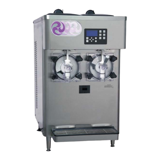
SECTION 1 DESCRIPTION AND SPECIFICATIONS DESCRIPTION The Stoelting E122 & F122 countertop machines are grav- ity fed. The machines are equipped with fully automatic controls to provide a uniform product. This manual is designed to help qualifi ed service personnel and opera- tors with the installation, operation and maintenance of the Stoelting E122 &... -
Page 8: Specifications
SPECIFICATIONS Model E122 Dimensions Machine with crate width 19-5/8’’ (49,8 cm) 28-1/2’’ (72,4 cm) height 35-1/2’’ (90,2 cm) 44’’ (111,8 cm) depth 30-1/4’’ (76,8 cm) 36’’ (91,4 cm) 275 lbs (124,7 kg) 278 lbs (126,0 kg) Weight Electrical 1 Phase, 208-240 VAC, 60Hz running amps 10.6A connection type... - Page 9 Model F122 Dimensions Machine with crate width 25-7/8’’ (65,7 cm) 31-3/4’’ (80,6 cm) height 38-1/4’’ (97,2 cm) 47-3/8’’ (120,3 cm) depth 33-3/8’’ (84,8 cm) 41-1/4’’ (104,8 cm) 390 lbs (176,9 kg) 458 lbs (207,7 kg) Weight Electrical 1 Phase, 208-240 VAC, 60Hz running amps 14.5A connection type...
-
Page 10: Component Settings
SPECIFICATIONS (CONTINUED) PEAK HEAT OF REJECTION Water Cooled Only Air Cooled Only Peak Heat of Peak Water Estimated Wa- Model Electrical AC Load Rating Rejection Usage ter Usage E122 1 PH, 60Hz 11,511 BTU/hr 2.3 GPM 1.4 GPM 8,850 BTU/hr F122 1 PH, 50Hz 14,947 BTU/hr... -
Page 11: Modes Of Normal Operation
MODES OF NORMAL OPERATION C. POST STIR After the freezing cycle ends, the drive motor continues Following is an explanation of the normal operation modes to run for a 12 second post stir. The post stir ensures the on the E122 and F122 (Refer to Figure 1-3). product does not freeze to the cylinder. -
Page 12: Operation During An Error Mode
Freezing Cycle Standby Pre Stir Post Stir Drive Motor & Drive Drive Cylinder Refrigeration Motor Motor Compressor Run Time Exceeds 20 Minutes 90 Seconds or Until Consistency Seconds Minutes Seconds Setting is Met Consistency check. Freezing Cycle will not start if Spigot Pull the product is at consistency. - Page 13 First Second Third Attempt Attempt Attempt Refrigeration Standby Standby Standby Pre Stir Pre Stir Pre Stir Cycle Cylinder Drive Drive Drive Refrigeration Motor Motor Motor Seconds Minutes Seconds Minutes Seconds Seconds Minutes Continues to operate until the cylinder is turned off then on again using the On/Off button.
- Page 14 Service Manual #513668 E122 & F122 Model Machines...
-
Page 15: Maintenance And Adjustments
SECTION 2 MAINTENANCE AND ADJUSTMENTS This section is intended to provide maintenance personnel 2.3 USER INTERFACE SCREENS with a general understanding of the machine adjustments. A. CURRENT STATUS It is recommended that any adjustments be made by a qualifi ed person. Current Status 01/01/01 12:34:56... -
Page 16: Performance Screens
D. FINE CONSISTENCY ADJUSTMENT 2.5 SETTINGS SCREENS The Fine Consistency Adjustment screen has no effect A. MODIFY OPERATING SETTINGS on machine operation. Modify Operating Settings 2.4 PERFORMANCE SCREENS Reset Serve Amount _ Basic Settings A. PERFORMANCE (1 OF 2) _ Advanced Settings _ Storage Settings Performance (1 of 2) _ User Preferences... - Page 17 The Temperature Units setting changes the units dis- C. ADVANCED SETTINGS played to Fahrenheit or Celsius. The Advanced Settings options have no effect on machine operation. The Service Contact Information option is used to change the service contact details including service company E.
-
Page 18: Utilities Screens
2.6 UTILITIES SCREENS B. TOUCHPAD LOCKUP Utilities (1 of 2) Touchpad Lockup Touchpad Status: Unlocked _ Adjust LCD Contrast _ Touchpad Lockup Do you want to lock keys _ Export Machine Stats _ Clean Options _ No Unlock Touchpad Next Utilities Menu _ Yes Lock Touchpad The Touchpad Lockup is used to lock and unlock the... - Page 19 The Clean Warning and Clean Lockout screens are Selecting Left or Right Output Control goes to a screen used to enable the clean warning mode or the clean that allows motors, solenoids, or the compressor to be lockout mode. When one of the modes is enabled and individually activated.
-
Page 20: Errors And Statistics Screens
G. UNIT CALIBRATION 2.7 ERRORS & STATISTICS SCREENS The Unit Calibration screens have no effect on machine The Errors & Statistics menu gives the Technician and Fac- operation. tory levels access to machine statistics and error history. H. MOTOR CALIBRATION The Motor Calibration screen has no effect on machine Errors and Statistics operation. - Page 21 C. MACHINE STATISTICS (3 OF 10) F. MACHINE STATISTICS (6 OF 10) Machine Statistics (3 of 10) Machine Statistics (6 of 10) Cylinder Right Cylinder Right Compressor Run Time 0000 hr Last Clean Cycle 00/00/00 Compressor Cycles 0000 00:00:00 AM Last Compressor Reset 00/00/00 Last Clean Time...
- Page 22 I. MACHINE STATISTICS (9 OF 10) L. STATUS AT TIME OF ERROR Status at Time of Error Machine Statistics (9 of 10) Operating Mode Cylinder Right Mix Levels Full Level Consistency 000.00 Current Hose Usage 0000 hr Input V/A/P 000.0V 00 00 Hose Service Limit 100 hr Outputs Status...
-
Page 23: Product Consistency Adjustment
2.8 PRODUCT CONSISTENCY ADJUSTMENT 2.10 PREVENTIVE MAINTENANCE The Consistency Adjustment Screw increases or de- Stoelting recommends that a maintenance schedule be creases product consistency by changing the amount of followed to keep the machine clean and operating properly. torque needed to complete a refrigeration cycle. Turn the A. -
Page 24: Extended Storage
The pump is now ready to operate. Place the D. SEMI-ANNUALLY hopper cover on the hopper. Disconnect the machine from the power source. Check drive belt for proper tension. 2.11 EXTENDED STORAGE Lubricate condenser fan motor with S.A.E. 20 Refer to the following steps for storage of the machine weight oil. -
Page 25: Refrigeration And Wiring Diagrams 3.1 Refrigeration Diagram
SECTION 3 REFRIGERATION & WIRING DIAGRAMS Service Manual #513668 E122 & F122 Model Machines... - Page 26 Service Manual #513668 E122 & F122 Model Machines...
- Page 27 Service Manual #513668 E122 & F122 Model Machines...
- Page 28 Service Manual #513668 E122 & F122 Model Machines...
- Page 29 Service Manual #513668 E122 & F122 Model Machines...
- Page 30 Service Manual #513668 E122 & F122 Model Machines...
- Page 31 Service Manual #513668 E122 & F122 Model Machines...
- Page 32 Service Manual #513668 E122 & F122 Model Machines...
- Page 33 Service Manual #513668 E122 & F122 Model Machines...
- Page 34 Service Manual #513668 E122 & F122 Model Machines...
-
Page 35: Replacement Parts
SECTION 4 REPLACEMENT PARTS DECALS AND LUBRICATION Quantity Part Description E122 F122 C-1000-26C Decal - Made In USA 208135 Brush - 4” X 8” X 16” (Barrel) 208380 Brush - 1/4” X 3” X 14” 208401 Brush - 1” X 3” X 10” 232091 Cap - Protective (Gray) - #490716... -
Page 36: Auger Shaft And Faceplate Parts
AUGER SHAFT AND FACEPLATE PARTS 630053 630053 336551 336551 2183447 2183447 2183099 2183099 570197 570197 2183751 2183751 2204226 2204226 666786 666786 482019 482019 624645 624645 2183444 2183444 2203370 2203370 2202068 2202068 2202181 2202181 624678 624678 624644 624644 2203224 2203224 2203555 2203555 624515 624515... -
Page 37: Hopper Parts
4.3 HOPPER PARTS 2187918 2187918 314453 314453 2203078 2203078 2187058 2187058 2203090 2203090 2203206 2203206 744252 744252 744281 744281 624607 624607 2187919 2187919 417006 417006 417031 417031 744273 744273 744609 744609 Quantity Part Description E122 F122 314453 Cover - Hopper 417006 Grid - Drip Tray (Vinyl Coated Metal) 417031... -
Page 38: Motor Components
MOTOR COMPONENTS 614222 614222 614232 614232 598155 598155 598296 598296 152207 152207 152340 152340 230441 230441 598026 598026 230447 230447 598039 598039 522720 522720 522302-SV 522302-SV 522304-SV 522304-SV Quantity Part Description E122 F122 152207 Belt - Gripnotch (AX29) (Each) 152340 Belt - Gripnotch (AX41) (Each) 230441 Capacitor Start... -
Page 39: Panels And Screws
PANELS & SCREWS Quantity Part Description E122 F122 644734 Screw - Panel (Sides & Rear) 647653 Screw - Panel (Header) 647886 Screw - Drip Tray Support Bracket 647899 Screw - Panel (Front) 649114 Screw - Panel (Rear Air Plenum) 2202679 Panel - Header 2202681 Drip Tray Support Bracket... -
Page 40: Electrical Components
ELECTRICAL COMPONENTS Quantity Part Description E122 F122 202245 Circuit Breaker (Air-Cooled Only) 229148 Cable - IntelliTec2 (Control Board to Display Board) 229158 USB Cable Extension 230632 Capacitor - Start (Compressor) 230649 Capacitor - Start (#282050 Compressor) 230654 Capacitor (Fan Motor) 230665 Capacitor - Fan Motor 230666... - Page 41 ELECTRICAL COMPONENTS (CONTINUED) 2177301 2177301 2183006 2183006 2177302 2177302 332563 332563 618363 618363 719127-SV 719127-SV 719128-SV 719128-SV F122 719111 719111 295017 295017 231079 231079 694200 694200 231084 231084 618157 618157 229158 229158 F122 521513 521513 521514 521514 521512 521512 521516 521516 295017 295017...
-
Page 42: Refrigeration
REFRIGERATION Quantity Part Description E122 F122 231107 Cap Tube Only 231107-SV Cap Tube & Drier Assembly 282032-SV Compressor - Copeland 1 PH - 60 Hz - R404A (No Capacitors) 282050 Compressor - 1 PH (50 Hz) (No Capacitors) 282094 Compressor - Copeland 1 PH (No Capacitors) 284000 Condenser - Air Cooled 284084... - Page 43 REFRIGERATION (CONTINUED) NOTE E112 shown 2202669 2202669 763012 763012 282094 282094 762482 762482 762978 762978 763422 763422 763482 763482 231107-SV 231107-SV 718794 718794 284000 284000 357105 357105 763674 763674 458003 458003 763674B 763674B 342006 342006 Service Manual #513668 E122 & F122 Model Machines...
-
Page 44: Auto Fill Parts
4.10 AUTO FILL PARTS 763596 763596 Quantity Part Description E122 F122 264096 Clamp - Oetiker (Tubing to Hopper Cover) 264235 Clamp - Metal (Tubing to Solenoid) 376086 Hose Adapter (1/4” x 3/8”) 756067 Tubing - 1/4” ID - Clear (Mix Inlet to Solenoid) (Per Inch) 192”...
Need help?
Do you have a question about the STOELTING E122 and is the answer not in the manual?
Questions and answers