Advertisement
Quick Links
Instruction Leaflet IL16956
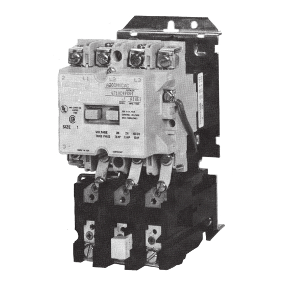
A200 Size 00, 0, 1 or 1P Single-Phase Motor Controller
THE CONTROLLER
The A200 motor controller, when wired as shown in Figure 4, will operate
as a full-voltage starter and will give protection against overload, but not
against short circuit currents, when wired and provided with overload relay
(OLR) heaters as listed in heater selection tables or when used with any
means of inherent protection activated by motor temperature.
The controller should be protected against short circuits by providing
branch circuit protection not to exceed the maximum protective device
ratings listed in Table I.
Effective May 2011
Supersedes January 1991
This industrial type control is designed to be
installed, operated, and maintained by adequately
trained workmen. These instructions do not cover
all details, variations, or combinations of the
equipment, its storage, delivery, installation, check-
out, safe operation, or maintenance. Care must be
exercised to comply with local, state, and national
regulations, as well as safety practices, for this
class of equipment.
AUXILIARY CONTACTS - TYPE J
One normally-open pole adjacent to the power
poles is supplied as the holding circuit auxiliary for
the Size 00, 0 and 1 . The Size 1P has a J20 auxiliary
contact assembly for that purpose. A maximum
off our Type J auxiliary units can be installed in the
recesses of each contactor. These may be mounted
with the terminals in line with the power poles or
may be mounted with the terminals in a right angle
relationship to the power poles. Auxiliary contact
mount by means of a spring clip and retainer screw.
To remove the unit rotate the retainer screw several
time (counterclockwise) and then slide the auxiliary
contact unit out of the recess.
Advertisement

Subscribe to Our Youtube Channel
Related Manuals for Eaton A200


Summary of Contents for Eaton A200
- Page 1 THE CONTROLLER The A200 motor controller, when wired as shown in Figure 4, will operate as a full-voltage starter and will give protection against overload, but not against short circuit currents, when wired and provided with overload relay...
- Page 2 A200 Size 00, 0, 1 or 1P Instruction Leaflet IL16956 Single-Phase Motor Controller Effective May 2011 EATON CORPORATION www.eaton.com...
- Page 3 Instruction Leaflet IL16956 A200 Size 00, 0, 1 or 1P Single-Phase Motor Controller Effective May 2011 EATON CORPORATION www.eaton.com...
- Page 4 A200 Size 00, 0, 1 or 1P Instruction Leaflet IL16956 Single-Phase Motor Controller Effective May 2011 EATON CORPORATION www.eaton.com...
- Page 5 Instruction Leaflet IL16956 A200 Size 00, 0, 1 or 1P Single-Phase Motor Controller Effective May 2011 EATON CORPORATION www.eaton.com...
- Page 6 Instruction Leaflet IL16956 A200 Size 00, 0, 1 or 1P Single-Phase Motor Controller Effective May 2011 Eaton Corporation Electrical Sector 1111 Superior Ave. Cleveland, OH 44114 United States 877-ETN-CARE (877-386-2273) Eaton.com Eaton is a registered trademark of Eaton © 2011 Eaton Corporation Corporation.
Need help?
Do you have a question about the A200 and is the answer not in the manual?
Questions and answers