Advertisement
Quick Links
Instruction Leaflet IL16963
A210, A250 Size 00, 0 or 1
Reversing Motor Controller
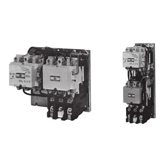
Figure 1. Size 1 A210 and A250 Motor Controllers
THE CONTROLLER
An A2l0 or A250 motor controller. when wired as shown in the
appropriate connection diagram will operate as a full voltage
starter and will give protection against overload, but not
against short-circuit currents, when wired and provided with
overload relay (OlR) heaters as listed in heater selection tables
or when used with any means of inherent protection activated
by motor temperature.
The controller should be protected against short circuits by
providing branch circuit protection not to exceed the maximum
protective device ratings listed in Table II.
Effective May 2011
Supersedes June 1989
This industrial type control is designed to be installed,
operated, and maintained by adequately trained workmen.
These instructions do not cover all details, variations,
or combinations of the equipment, its storage, delivery,
installation, check out, safe operation, or maintenance. Care
must be exercised to comply with local, state, and national
regulations, as well as safety practices, for this class of
equipment.
AUXILIARY CONTACTS - TYPE J
Two Jll auxiliary contacts, each with one normallyopen pole
and one normally-closed pole are supplied with reversing
controllers. One pole is used as the holding circuit auxiliary.
The other pole serves as an electrical interlock. A maximum
of three auxiliary units can be installed in each reversing
contactor with terminals either in line or in a right angle
relationship to the power poles. Auxiliary contacts mount by
means of a spring clip and retainer screw. To remove the unit
rotate the retainer screw several times (counterclockwise)
and then slide the auxiliary contact unit out of the recess.
Advertisement

Related Manuals for Eaton A210


Summary of Contents for Eaton A210
- Page 1 Supersedes June 1989 A210, A250 Size 00, 0 or 1 Reversing Motor Controller Figure 1. Size 1 A210 and A250 Motor Controllers THE CONTROLLER This industrial type control is designed to be installed, operated, and maintained by adequately trained workmen.
- Page 2 Figure 4. Type A Block Overload Relay (OLR) TYPE A OVERLOAD RELAY (See Figure 4) The A210 or A250 motor controller can be equipped with a Type A block type non-ambient compensated overload relay (unmarked and with red reset rod) or with a block type temperature compensated overload relay (marked “ambient compensated”...
- Page 3 1% for each OC controller ambient exceeds motor ambient. COIL The A210 or A250 motor controller is available with single or dual voltage coils. When equipped with a single voltage coil, each contactor is wired as shown in Figure 7 , 8, 9, or 10. A connection diagram for a dual voltage coil is shown in Figure 5.
- Page 4 Instruction Leaflet IL16963 A210, A250Size 00, 0 or 1 Reversing Motor Controller Effective May 2011 SHORT-CIRCUIT WITHSTAND RATINGS This motor controller is suitable for use on a circuit capable of delivering not more than the current (rms symmetrical amperes) shown below in circuits rated not more than the voltage shown below: Figure 5.
- Page 5 Reversing Motor Controller Effective May 2011 Figure 9. A250 Connection Diagram (Type B OLR) Figure 7. A210 Connection Diagram (Type B OLR) Figure 8. A210 Connection Diagram (Type A OLR) Figure 10. A250 Connection Diagram (Type A OLR) EATON CORPORATION www.eaton.com...
- Page 6 Instruction Leaflet IL16963 A210, A250Size 00, 0 or 1 Reversing Motor Controller Effective May 2011 Figure 11. Size 1 Contactor (exploded View) MAINTENANCE - First Turn Off Power To Replace The Coil To Inspect Contacts Refer to Figure 11. Loosen the assembly screws (10) located to the immediate top and bottom of the arc box.
Need help?
Do you have a question about the A210 and is the answer not in the manual?
Questions and answers