Advertisement
Quick Links
INSTRUCTION MANUAL
Introduction
The HA1 hermetic analyzer is designed to pro-
vide the service technician with an easy to use,
reliable test instrument. To obtain the maxi-
mum benefit from
the HA1, please take time to read these
instructions.
Note: Under some test conditions 120 V AC
may be present on a test cable. Refer to section
on operation.
Features include
• Free locked rotors by reversing motor action
• Indicates continuity and ground faults by front
panel indicator lights
• Front panel input jacks to facilitate VOM
measurement of voltage and resistance
• Dual 120/240 V AC operation
• Color coded for easy use
Safety Notes
Before using this instrument, read all safety
information carefully. In this manual the word
"WARNING" is used to indicate conditions or
actions that may pose physical hazards to the
user. The word "CAUTION" is used to indicate
conditions or actions that may damage this
instrument.
International Symbols
Find Quality Products Online at:
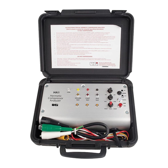
Controls and Indicators
HA1
1. PWR Breaker: This is a combination 25A circuit
breaker and a POWER ON switch.
2. CAP100/200/300: Selects one of the three starting
capacitor ranges.
Position
100MFD
200MFD
300MFD
3. REV/OFF/FWD: Switch determines the mode of
operation of the compressor. In the FWD position,
power is applied to the compressor motor run
winding, and the start capacitor is connected to the
START cable. In the REV position, power is applied
to the compressor motor start winding and the start
capacitor is connected to the RUN cable. In the OFF
position, the power circuit to the motor is broken.
The REV position is momentary. The OFF and FWD
positions are sustained.
4. FAULT/CONT./START: Is a multi-function switch.
The FAULT (momentary action) position is used
to check for shorts between the COM and the RUN/
START windings. The CONT. (sustained action) posi-
tion is used to check for GROUND, RUN and START
continuity. In the START (momentary action) position,
the start capacitor is connected to the
compressor motor through the REV/OFF/FWD switch.
5. Ground Test (Yellow): This push button switch
tests for ground continuity between system ground
and the frame of the appliance being tested.
The HA1 introduces an "artificial ground" to make
possible the testing for short circuits between the
motor winding and the frame of appliances which
may not be directly grounded. For example, units
with two wire power cords would not be connected
to system ground (unless a separate ground
connection were present).
6. Start Test (Red): This push button switch test two
conditions, depending on the position of the FAULT/
CONT./START switch.
Switch Position
FAULT
CONT.
7. Run Test (Black): This push button switch tests
two conditions, depending on the position of the
FAULT/CON./START switch.
Switch Position
FAULT
CONT.
8. Indicator Light: LINE NORM (white)/REV (red).
These lights are used to indicate the "condition" of
the power source to which the HA1 is connected.
Line Voltage Indicator Light
110 V AC
GlobalTestSupply
www.
220 V AC
Range
88-180MFD
161-193MFD
249-301MFD
Condition Tested
Short between START winding
and frame
Continuity of START winding
Condition Tested
Short between RUN winding
and frame
Continuity of RUN winding
Status
NORM on/REV off
Normal
REV on/NORM off
Neutral and line wires
reversed at power
receptacle. Refer to
CAUTION under section on
110 V AC operation
NORM and REV
System ground open or not
on (half intensity)
connected at power receptacle
.com
NORM and REV
Normal
on (full intensity)
9. Test Jacks: The four test jacks are connected
directly to the test cable of the corresponding
color:
COMMON = white
GROUND* = yellow
START = red
RUN = black
The purpose of the test jacks is to facilitate
resistance and voltage readings by enabling
voltmeter/ohm meter test leads to be
connected to the compressor motor circuit
by inserting them into the appropriate jack
at the HA1 front panel.
*Since this cable is an "artificial" ground line it is colored
yellow instead of green.
Operating Instructions
NOTE: Every effort has been made to make the
HA1 a safe and versatile tester. However, under
some circumstances line voltage may be present on
the HA1 test cables when the control switches are in
the OFF position. For this reason it is very important
to read and become familiar with the section on
Operating Instructions.
The following procedures have been detailed so a
thorough understanding of the operation sequence
may be gained. In practice, the following tests may
be performed very quickly.
110 V AC Operation
CAUTION!
The HA1 is wired so that the white COMMON test
cable is connected to the neutral side of the line.
The red START and black RUN cables are connected
to the hot side of the line by the POWER BREAKER
switch and the REV/OFF/FWD switch. If the 110 V AC
receptacle has been accidentally reverse wired, the
white COMMON cable will be "hot" as soon as the
HA1 is plugged into the power receptacle. To warn
against such a condition, the red REV LINE indica-
tor will light as soon as the HA1 is plugged into a
grounded receptacle. In this case follow procedure B
for reversed line condition.
A. Normal Test Procedure
1. The REV/OFF/FWD switch must be in the
OFF position.
2. Plug the HA1 into a grounded 110 V AC
receptacle and turn on the POWER switch.
This is a push on - push off switch. The white
NORM LINE indicator should light.
NOTE: If the receptacle is ungrounded, both the
NORM and the REV LINE indicator will light, but at
half intensity. The absence of a grounded line will
not prevent any of the following tests from being
made. IMPORTANT: verify that the receptacle is
not also reverse wired by measuring the voltage
between the white COM cable and a ground
connection. A reversed line will measure 110 V AC.
A normal line will measure zero volts. If the
receptacle is reverse wired, follow procedure B.
3. Remove power to the unit which is to be tested.
4. Remove and identify the connectors going to
the common, start, and run terminals of the
compressor motor.
5. Connect the test cables of the HA1 to the
compressor motor.
sales@GlobalTestSupply.com
• Yellow GROUND cable to compressor
motor frame
• Red START cable to the start terminal
• Black RUN cable to the run terminal
• Leave the white COMMON cable
disconnected until step 7
Advertisement

Related Manuals for UEi HA1


Summary of Contents for UEi HA1
- Page 1 REV LINE indica- • Front panel input jacks to facilitate VOM conditions, depending on the position of the FAULT/ tor will light as soon as the HA1 is plugged into a measurement of voltage and resistance CONT./START switch.
- Page 2 If either the run or start winding indicate open, CAUTION! stop the test and replace the unit. The white COM cable will be hot as soon as the HA1 line Specifications 9. Select the appropriate motor start capacitor. cord is connected to 220 V AC. Always make sure that power to the HA1 is shut off before connecting the HA1 10.
Need help?
Do you have a question about the HA1 and is the answer not in the manual?
Questions and answers