Table of Contents
Advertisement
Quick Links
Advertisement
Table of Contents

Related Manuals for Laguna Tools MSANWB25X60-1K-7.5-0197


Summary of Contents for Laguna Tools MSANWB25X60-1K-7.5-0197
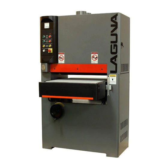
- Page 1 Widebelt Sander Manual Model 25" & 37" Widebelt Sander LAGUNA TOOLS 2072 Alton Parkway Part No. MSANWB25X60-1K-7.5-0197 Irvine, California 92606 Part No. MSANWB37X60-1K-15-0197 Ph: 800.234.1976 © 2018 Laguna Tools, Inc. All rights reserved. www.lagunatools.com...
-
Page 3: Table Of Contents
Table of Contents Page number Safety Rules Warranty Noise Emission Specification Sheet Receiving your Widebelt Sander Introduction to your Widebelt Sander Parts of the Widebelt Sander What you will Receive Where to locate your Widebelt Sander Unpacking your Widebelt Sander Assembly and Setup Adjusting the Widebelt Sander Running the Sander... -
Page 4: Safety Rules
Safety Rules As with all machinery, there are certain hazards involved with the o peration and use. Using it with caution will considerably lesse n the poss ibility of personal injury. However, if normal safety precautions are overlooked or ignored, personal injury to the operator may result. -
Page 5: Warranty
Machines sold through dealers must be registered with Laguna Tools within 30 days of purchase to be covered by this warranty. Laguna Tools guarantees all new machines and accessories sold to be free of manufacturers’... -
Page 6: Noise Emission
Noise Emission Notes concerning noise emission. Given that there exists a relationship between noise level and exposure times, it is not precise enough to determine the need for supplementary precautions. The factors affecting the true level of exposure to operators are clearly the amount of time exposed and the characteristics of the working environment, such as other sources of dust and noise –... -
Page 7: Specification Sheet
Specification Sheet for Widebelt Sander... -
Page 8: Receiving Your Widebelt Sander
All damage must be noted on the delivery documents and signed by you and the delivery driver. You must then contact the seller (Laguna Tools) as soon as is practical. If damage is found after delivery, contact the seller as soon as is practical. -
Page 9: Parts Of The Widebelt Sander
Parts of the Widebelt Sander The Widebelt Sander consists of a number of major parts, which are discussed in this manual. Take the time to read this section and become familiar with the machine. Identification. There is a plate on the machine listing all the manufacturing data, including the model. - Page 10 health reasons and also because the belt will clog and poor surface finish will result. It is not possible to be exact when recommending the size of dust collector to be used; this will depend on the type of work that the machine is used for. It is recommended that a dust collector with a minimum of 3500 cubic feet/minute be attached to the sander.
- Page 11 12. Bed vertical drive motor The bed of the machine can be adjusted vertically by using the switches on the control panel. The switches control the motor and gearbox. 13. Table vertical adjustment chain The bed vertical adjusting handle (front of the machine) moves a chain that rotates four cogs.
- Page 12 17. Platen adjuster The platen can be adjusted lower than the sanding rollers. The amount below the rollers will vary depending on the type of sanding being conducted. If conducting rough sanding, the platen is adjusted above the sanding rollers so that it is not in contact with the sanding belt.
-
Page 13: What You Will Receive
25. Main drive motor The main motor powers the sanding belt. 26. Motor disc brake The disc brake is air operated and stops the main drive motor when power is removed. What you will Receive with the Widebelt Sander Door keys Spare platen Grease gun flexible extender backer... -
Page 14: Unpacking Your Widebelt Sander
3. Solid floor. You should select a solid, flat floor, preferably concrete or something similar. 4. Locate it close to a power source and dust collection. 5. Allow an area for the storage of blanks, finished products and tools. Unpacking Your Widebelt Sander To unpack your sander, you will need tin snips, knife, screwdriver and a wrench. -
Page 15: Assembly And Setup
Assembly and Setup Very little assembly and setup is required, as the machine comes fully assembled. You will have to fit the sanding belt and connect the air and electricity. Cleaning the machine Remove the rust protection grease with WD 40 or a similar solvent. It is important that you remove all the grease. - Page 16 Connecting the air supply The input air regulator regulates the air pressure that is supplied to the machine. The machine is supplied with an air connector, to which you can connect your air supply. You will require an air supply that can deliver a constant minimum pressure of 6 bar.
- Page 17 Fitting the sanding belt Note. Disconnect the sander from the electrical supply. Clamp Spacer Sanding belt direction arrow Roller tension switch 1. Rotate the roller tension switch counter-clockwise to lower the tension roller. 2. Rotate the clamp counter-clockwise and lift out. Note.
- Page 18 Clamp and spacer assembled Belt sensor Sanding belt assembled Note. Never run the sander without the spacer and clamp assembled, as this will damage the machine. Note. The machine is supplied with a sanding belt, and this may not be the correct one for your work.
-
Page 19: Adjusting The Widebelt Sander
Starting the sander 1. Connect the sander to the power. 2. Press the table up and down keys. The table should move smoothly. Note. Check that the table moves in the correct direction according to the arrow that is being pressed. If the table moves in the incorrect direction, you will probably have the input electrical wiring wrong and will need to change phase wires (3-phase machine only). - Page 20 Electronic control panel Quick set The control panel is set on the front of the machine. It has a number of switches. 1. Bed up/down buttons. 2. Sanding belt start/stop buttons. 3. Conveyor start/stop buttons. 4. Emergency stop switch. 5. Power indicator light. Quick set The sander has a device on the side that is used to set the...
- Page 21 Belt speed The speed of the belt can be adjusted to between high and low. It is a matter of experience when selecting the correct speed. Changing conveyor speed. 1. Disconnect the power to the machine. 2. Remove the conveyor drive cover. 3.
- Page 22 The belt drive gearbox is filled with oil. As the oil heats, it expands and causes pressure within the gearbox. To relieve this pressure, there is a small hole on the side of the bolt. To ensure there is no leakage during shipping, the hole is sealed with a small plastic pin.
- Page 23 The sanding belt is tensioned by the central belt tension piston. The piston is activated by the sanding belt tension switch. This switch must be activated prior to starting the sander. The sanding belt oscillates along the top and bottom rollers. This greatly enhances the performance of the sander and reduces the chances of lines and marks on the job.
-
Page 24: Running The Sander
4. With the sanding belt fitted, run the sanding head and note the time that it takes the sanding belt to oscillate in both directions. The time taken to oscillate in either direction should be the same. 5. If the oscillation to the right is longer than the time for the sanding belt to oscillate to the left, adjust the control knob (5) to the right. - Page 25 Scale Scale Clamp Adjusting handle The scale is very fine and has a complete range of +2mm (0.08") –2mm (0.08"). Adjust the platen as follows. 1. Loosen the clamp. 2. Move the platen with the adjusting handle to the required setting. 3.
- Page 26 Check that all the safety switches are functioning Bed safety switch Bed upper limit Bed lower limit switch switch 1. Lower the bed until it hits the lower limit switch. The bed travel must stop once the switch is activated. 2.
-
Page 27: Maintenance And Troubleshooting
Maintenance and Troubleshooting Note, When conducting maintenance, disconnect the machine from the electricity and the air supply. General Keep your machine clean. At the end of each day, clean the machine. Wood contains moisture, and if sawdust is not removed, it will cause rust. In general, we recommend that you only use a Teflon-based lubricant. - Page 28 hours of operation. Greasing the bearings will flush out any sawdust that has gotten pasted into the seals. After greasing, wipe off any excess. A grease gun extender is supplied to ease access to the bearings. Grease nipple Grease nipple Grease nipple Grease nipple with cover removed Grease nipple...
- Page 29 Ceramic rollers The ceramic rollers must be checked regularly for wear, cracks and general damage. Two spares are supplied. Platen graphite pad Fixing screws The sanding belt runs on a graphite pad that is backed by a felt pad. The graphite will wear out eventually.
- Page 30 3. Loosen the lock nuts and adjust the pressure rollers so that they are both just touching the panel. This must be completed at the extremities of the rollers to ensure that they are parallel. 4. With the rollers parallel, adjust the rollers to the required setting and lock the lock nuts.
- Page 31 2. Turn the conveyor on. 3. If the conveyor is running to the right, turn the right-hand adjusting screw clockwise. Only make very small adjustments and wait for the conveyor to settle before making additional adjustments. It is better to take your time and not rush the adjustments. 4.
- Page 32 Conveyor vertical adjustment motor adjustment The drive belts will need to be adjusted from time to time. To adjust, loosen the lock nut and turn the adjusting nut (on top of bracket) until the correct tension is achieved. Do not forget to re-tighten the lock nut after the adjusting has been completed. Note.
- Page 33 Troubleshooting Problem Possible cause Solution Display fails to come on. Breaker tripped. Reset breaker. Power switched off. Switch power on. Display faulty. Replace display. Display shows incorrect Incorrect figures input Input correct figures. figures. into computer. Computer corrupted. Turn power off then on. Display faulty.
- Page 34 Burn marks on the job. Sanding belt is too fine Replace the sanding belt for the job. with coarser grit sanding belt. Sanding belt clogged. Clean belt with belt cleaning stick or replace the sanding belt. Deep sanding marks or Sanding belt too coarse.
- Page 35 Sander will not stop. This is a very rare Switch faulty. Replace occurrence, as the the switch. machine is designed to fail-safe. If it should occur and you cannot fix the fault, seek professional assistance. The machine must be disconnected from the power and never run until the fault has been rectified.
- Page 36 Machine vibrates. Machine not level on the Re-level the machine, floor. ensuring that it has no movement. Broken, damaged or Replace the sanding belt. defective sanding belt. Loose fixing bolts. Check all the fixing bolts and tighten if found loose. Respective noise.
- Page 37 Belt not centralized on Adjust sanding belt top roller. adjuster. Sanding belt slips on Tension cylinder not Check for air leaks. Low rollers. exerting sufficient air pressure. pressure. Sanding belt will not start. No tension on the No air pressure. sanding belt.
-
Page 38: Electrical Drawing
Electrical Drawing... - Page 39 Electrical Drawing...
-
Page 40: Exploded View Drawings
Exploded View Drawings... - Page 41 0000 ITEM NO DESCRIPTION GRAPHITE HOLDER LIMIT SWITCH TUBE TOOL BOX FELT GRAPHITE 007-1 SANDING BELT #100 007-2 SANDING BELT #180 PHILLIP’S SCREWDRIVER FLAT SCREW DRIVER WRENCH 8 X 10 WRENCH 12 X 14 WRENCH 17 X 19 HEX WRENCH...
- Page 43 1000 1000 ITEM NO DESCRIPTION ITEM NO DESCRIPTION MACHINE FRAME LIMIT SWITCH MOTOR BASE LIMIT SWITCH PLATE MOTOR BASE HINGE SCREW 1/4 " " X 1/2 NUT 1/2" PLAIN WASHER 1/4" MOTOR BASE ADJUSTMENT ROD FLAT HEAD SCREW SPRING WASHER 1/2" SPRING WASHER SCREW BRAKE BRACKET...
- Page 45 2000 2000 ITEM NO DESCRIPTION ITEM NO DESCRIPTION ELEVATION SCREW HEADLESS SCREW 1/4 " X 1/2" SCREW 5/16" X 1" SPRING WASHER 5/16 " PLAIN WASHER 5/16" SCREW 5/16" X 3/4" SPRING WASHER 5/16" HEADLESS SCREW 1/4 " X 1/2" SPRING WASHER 3/8"...
- Page 47 3000 3000 ITEM NO DESCRIPTION ITEM NO DESCRIPTION CONVEYOR TABLE NUT 5/16" CONVEYOR BELT FRONT BRAKE COVER GEARBOX FIX PLATE LIMIT SWITCH CUSHION ROUND PHILLIPS SCREW 3/16" PLAIN WASHER 3/8" SCREW 1/2" SCREW 3/8" INFEED ROLLER SHAFT OUTFEED ROOLER INFEED ROLLER BEARING UCF206 BEARING 6206ZZ REDUCER...
- Page 49 4000 ITEM NO DESCRIPTION PISTON SLIDERAIL PISTON BRACKET SPRING PIN 10M/M X 35M/M HEADLESS SCREW 1/4" SCREW 5/16" NUT 5/16" SCREW 5/16" SPRING WASHER 5/16" PISTON ROLLER SHAFT PISTON ROLLER BEARING 6001 SHAFT BEARING COLLER HEADLESS SCREW 1/4"...
- Page 51 5000 5000 ITEM NO DESCRIPTION ITEM NO DESCRIPTION BEARING HOUSING FASTENING TUBE RUBBER ROLLER HEADLESS SCREW 1/4" X 3/8" FASTENING TUBE KEY 1/4" X 25MM BEARING UCC206 SPRING PULLEY HOUSING OF FIXING SHAFT HEX SOCKET HEAD SCREW 5/16" X 1 1/4" FIXING SHAFT OF GRAPHITE BRACKET KEY 5/16"...
- Page 53 6000 6000 ITEM NO DESCRIPTION ITEM NO DESCRIPTION SQUARE FRAME FLAT HEAD SCREW M$ X 12MM SQUARE FRAME SEAL (RIGHT) SQUARE FRAME SEAL (LEFT) UPPER ROLLER BRACKET FLAT HEAD SCREW 1/4" X 3/4" UPPER ROLLER SPRING WASHER 3/8" UPPER ROLLER BRACKET SCREW 3/8"...
- Page 55 7000 ITEM NO DESCRIPTION UPPER FRAME COVER PHILLIP’S SCREW LEFT DOOR, UPPER FRAME RIGHT DOOR, UPPER FRAME DOOR LOCK SCREW PLAIN WASHER 5/16" RIGHT DOOR, LOWER FRAME 109-1 LEFT DOOR, LOWER FRAME " SCREW 1/4" X 1/2" FRONT PROTECTION PLATE...
- Page 57 8000 8000 ITEM NO DESCRIPTION ITEM NO DESCRIPTION ELECTRICAL CONTROL BOX PU CONNECTOR HINGE CABLE CONNECTOR PU CONNECTOR ELECTRICAL CONTROL BOX OF DOOR BASE PLATE AMP METER NUT 1/4" EXCHANGE SWITCH SPRING WASHER 1/4" 128-1 START SWITCH CONTROL PANEL 128-2 START SWITCH PHILLIP’S SCREW M4 X 8MM 128-3...
- Page 59 9000 9000 ITEM NO DESCRIPTION ITEM NO DESCRIPTION FILTER CUP CONNECTOR PRESSURE GAUGE FLEXIBLE HOSE BRONZE CONNECTOR FLEXIBLE HOSE FLEXIBLE HOSE FLEXIBLE HOSE AIR SWITCH FLEXIBLE HOSE ELBOW FLEXIBLE HOSE SCREW 3/16" FLEXIBLE HOSE ELBOW FLEXIBLE HOSE SOLENOID VALVE FLEXIBLE HOSE T-JOINT FLEXIBLE HOSE CONNECTOR...
- Page 61 8000 8000 ITEM NO DESCRIPTION ITEM NO DESCRIPTION ELECTRICAL CONTROL BOX CABLE CONNECTOR HINGE PU CONNECTOR AMP METER ELECTRICAL CONTROL BOX OF DOOR BASE PLATE 128-1 START SWITCH NUT 1/4" 128-2 START SWITCH SPRING WASHER 1/4" 128-3 START SWITCH CONTROL PANEL 129-1 STOP SWITCH PHILLIP’S SCREW M4 X 8MM...
- Page 62 Laguna Tools is not responsible for errors or omissions. Specifications subject to change. Machines may be shown with optional accessories. © 2018, Laguna Tools, Inc. LAGUNA® and the LAGUNA Logo® are the registered trademarks of Laguna Tools, Inc. All rights reserved.
Need help?
Do you have a question about the MSANWB25X60-1K-7.5-0197 and is the answer not in the manual?
Questions and answers