Table of Contents
Advertisement
Quick Links
1632
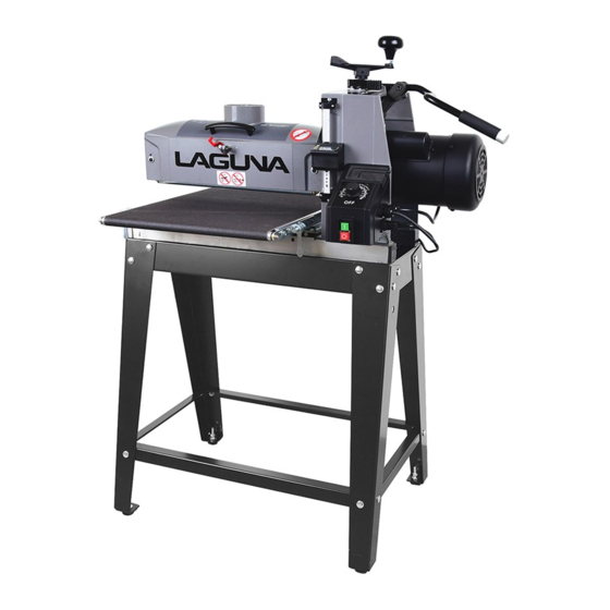
Drum Sander
Operating Instructions
Producer:
Laguna Tools Inc
744 Refuge Way, Suite 200
Grand Prairie, Texas 75050
USA
Phone: +1 800-234-1976
Website: www.lagunatools.com
Distributor:
IGM nástroje a stroje s.r.o.
Ke Kopanině 560, 252 67, Tuchoměřice
Czech Republic, EU
Phone: +420 220 950 910
PDF ONLINE
E-mail: sales@igmtools.com
www.igmtools.info
Website: www.igmtools.com
2022-03-30
151-1632 LAGUNA Drum Sander Manual EN v2.0 A4ob
Advertisement
Table of Contents

Related Manuals for Laguna Tools 1632


Summary of Contents for Laguna Tools 1632
- Page 1 Phone: +1 800-234-1976 Website: www.lagunatools.com Distributor: IGM nástroje a stroje s.r.o. Ke Kopanině 560, 252 67, Tuchoměřice Czech Republic, EU Phone: +420 220 950 910 PDF ONLINE E-mail: sales@igmtools.com www.igmtools.info Website: www.igmtools.com 2022-03-30 151-1632 LAGUNA Drum Sander Manual EN v2.0 A4ob...
-
Page 2: Ec Declaration Of Conformity
EN 61000-4-4: 2012 Electrical fast transient/burst requirements (EFT/Burst) EN 61000-4-6: 2014 Immunity to conducted disturbances, induced by radio-frequency fields (CS) Responsible for the documentation: Head Product Management, Laguna Tools Inc. Name : Torben Helshoj Responsibility Authorized Signature Date : Oct. -
Page 3: Dear Customer
Dear Customer, many thanks for the confidence you have shown in us with the purchase of your new Laguna Tools machine. This manual has been prepared for the owner and operators of an IGM LAGUNA 1632 SuperMax Drum Sander to promote safety during installation, operation and maintenance procedures. -
Page 4: Transport And Setup
• Use only three-wire cables with a euro plug and an appropriate socket. 4. Machine Specification Type: 1632 Power: 230 V / 50 Hz / 1 phase Recommended circuit breaker: 16 A, rating C (16/1/C) Current at maximum load: 6,5 A... - Page 5 IInstalling Drum Sander 1. For easier access to the machine, peel back the plastic liner, cut the box at the corners, and fold down the 4 sides of the box. 3. Note: Long rail on top of short rail and both rails inside of legs. 2.
-
Page 6: Setting And Adjustment
16 A, rating C (16/1/C)). Do not plug the machine into the power supply until it is fully setup. 6. Screw the height adjustment knob into the handle and tighten it down. 6. Setting and Adjustment 6.1 Setting the Drum Sander Checking Drum Alignment UNPLUG THE MACHINE FROM THE POWER SOURCE! During initial setup only. - Page 7 Connecting Dust Collection 5. Raise the head of the sander by rotating the height adjustment handle up Dust collection is necessary for the drum sander. The sander comes exactly one full turn. equipped with a 100 mm (4”) diameter dust exhaust port at the top of the cover.
-
Page 8: Machine Operation
7. Machine Operation 2. Wind the abrasive around the drum, being careful not to overlap the Proper Abrasive Position windings. The tapered cut of the wrap end should follow the edge of the Position the abrasive in the slot with sufficient room between the inside drum. - Page 9 Button Reference and Use Calibration It is helpful to familiarize these buttons and their purpose with the Wixey There are three typical variations of calibration. The first variation (Type 1) is for the DRO to show the sanded thickness of the material.
- Page 10 the just sanded piece. Now the readout will show increase the feed rate to the pre-selected speed. the amount of stock removed per sanded pass in “INC” mode. 2. To change back to the original (Type 1) calibration press the “ABS/INC” Stock Feeding Operation button to change back to “ABS”...
-
Page 11: Maintenance
Tension Roller Contact Adjustment 8. Maintenance The tension rollers are factory set for the most versatile use. Monthly Maintenance 1. To adjust tension roller contact, loosen the four socket head screws • Lubricate conveyor bushings and check for wear. holding the tension roller brackets (2 per side; front and back). •... -
Page 12: Troubleshooting
4. Remove the two nuts and washers from outboard (left) side. Lift IGM LAGUNA 1632 Drum Sander Folding Infeed/Outfeed Tables the conveyor and remove it from the sander. Set conveyor on motor Order code: 151-1632FT side. Avoid tearing the belt on any edges underneath the conveyor bed during removal. - Page 13 TROUBLESHOOTING GUIDE: MACHINE Problem Possible Cause Solution Drum height adjustment works improperly Improper adjustment of height control Readjust height control Replace the bearing. Knocking sound while running Bearing worn Contact distributor Inadequate support of stock Use roller stands to support stock Sniping of wood (gouging near end of Conveyor drive or driven rollers higher than Readjust rollers...
-
Page 14: Head Assembly
16-32 - HEAD ASSEMBLY www.igmtools.com -14-... - Page 15 # PART NO DESCRIPTION SIZE # PART NO DESCRIPTION SIZE Key Part Number Description Specification 89 71632-189 O-Ring 1 71632-101 Motor 90 71632-190 Screw M5x0.8x12 2 480BS-102 Strain Relief, motor 7P-2 91 71632-191 Cover, Base-Control Box 3 71632-103 Main Cord, Inverter to Control Box 92 71632-192 Switch, ON/OFF 4 480BS-104 3/16"SQx3/4"...
-
Page 16: Wiring Diagram
16-32 - WIRING DIAGRAM BLUE BLUE 16-32 - OPEN STAND ASSEMBLY # PART NO DESCRIPTION SIZE 1 480BS-501 LEG, LEFT LEG, RIGHT (WITH TOOL 2 480BS-502 HOLDER) 3 71632-303 TOP CROSS BRACE, LONG 4 71632-304 TOP CROSS BRACE, SHORT LOWER CROSS BRACE 5 71632-305 RAIL, LONG LOWER CROSS BRACE... - Page 17 ..71632-205 ....MOTOR MOUNTING PLATE ........................... 480BS-113 ....SET SCREW ................ 1/4"-20 X 1/4" ............. 480BS-224 ....HEX CAP SCREW ............... 1/4"-20 X 3/4" ............. 16-32 - CONVEYOR AND MOTOR ..480BS-154 ....OILITE BUSHING ............................... 3 ..
- Page 18 IGM nástroje a stroje s.r.o., Ke Kopanině 560, Tuchoměřice, 252 67, Czech Republic, EU +420 220 950 910, www.igmtools.com © 2022 IGM nástroje a stroje s.r.o.
Need help?
Do you have a question about the 1632 and is the answer not in the manual?
Questions and answers