Table of Contents
Advertisement
Quick Links
Advertisement
Table of Contents
Troubleshooting

Related Manuals for Laguna Tools Pro Widebelt Series


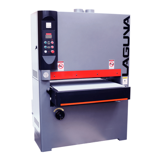
Summary of Contents for Laguna Tools Pro Widebelt Series
- Page 1 PRO SERIES WIDEBELT SANDER MANUAL LAGUNA TOOLS 2072 Alton Parkway Irvine, California 92606 Ph: 800.234.1976 MSANWB37X75-10-0197 www.lagunatools.com © 2018, Laguna Tools, Inc. LAGUNA® and the LAGUNA Logo® are the registered trademarks of Laguna Tools, Inc. All rights reserved.
- Page 3 Safety Rules As with all machinery there are certain hazards involved with the operation and use. Using it with caution will considerably lessen the possibility of personal injury. However, if normal safety precautions are overlooked or ignored, personal injury to the operator may result. If you have any questions relative to the installation and operation, do not use the equipment until you have contacted your supplying distributor.
- Page 4 Machines sold through dealers must be registered with Laguna Tools within 30 days of purchase to be covered by this warranty. Laguna Tools guarantees all new machines and accessories sold to be free of manufacturers’...
-
Page 5: Table Of Contents
INDEX GENERAL SAFETY RULES --------------------------------------------------------------------------------- SPECIFIC SAFETY RULES ---------------------------------------------------------------------------------- BEFORE OPERATION ---------------------------------------------------------------------------------------- INSTALLATION - STEP 1. MOVING THE MACHINE --------------------------------------------------------------- STEP 2. CLEANING THE MACHINE ------------------------------------------------------------ STEP 3. POWER WIRE CONNECTIONS ------------------------------------------------------- STEP 4. AIR CIRCUIT CONNECTION ---------------------------------------------------------- STEP 5. DUST HOOD CONNECTION ----------------------------------------------------------- STEP 6. -
Page 6: General Safety Rules
GENERAL SAFETY RULES GENERAL SAFETY RULES READ THE MANUAL: Read,understand and follow the safety and DO NOT OVER-REACH: Maintain a balanced distance and keep operating instructions found in this manual. Know the limitations and your body under control at all times. Do not over-reach or use hazards associated with the Wide Belt Sander. -
Page 7: Specific Safety Rules
SPECIFIC SAFETY RULES SPECIFIC SAFETY RULES READ THE MANUAL:Do not operate the wide belt sander until you UNATTENDED. Person not familiar with the sander's operation could injure read,understand and are able to follow the safety instructions found in this themselves or others. manual. -
Page 8: Before Operation
BEFORE OPERATION Before operating sander, make sure that : 1. Dust collection system is turned on. 2. Sanding belt specification is correct 3. Sanding belt is running in proper direction 4. Sanding belt tension is correct 5. All screws and handels are tightened securely. 6. -
Page 9: Installation
INSTALLATION- STEP 1. MOVING THE MACHINE STEP 3. POWER WIRE CONNECTIONS The machine should be moved to the work site with a folk lift. Make sure Before connecting the power wires of the machine to the power supply, make that the fork lift's loading capacity is adequate for the machine's weight. sure the voltage, hertz,phase and amperage are compatible. -
Page 10: Step 4. Air Circuit Connection
STEP 4. AIR CIRCUIT CONNECTION STEP 5. DUST HOOD CONNECTION The air circuit connector is on the Filter/Regulator unit located on the Connect your dust collection system to the machine 's dust hood back side of sander. Connect your air supply to the 5/16" air source (located on top) with a 4"... -
Page 11: Step 6. Install Sanding Belt
INSTALL SANDING BELT INSTALL SANDING BELT 1. Disconnect machine from power source 6. Insert new belt by starting first on the upper roller ( F ), then the lower 2. Shut "OFF" the air tension switch ( C ). roller. Center the belt while avoiding contact with limit switch fingers that 3. -
Page 12: Major Parts Of The Machine
MAJOR PARTS OF THE MACHINE --... -
Page 13: Brake System
BRAKE SYSTEM The sander will stop automatically if any of the follow occur - 1. No air supply to the machine 2. No sanding belt mounted 3. Inproper belt tension 4. Sanding belt rubs out of track 5. If the sanding belt breaks, all movement will be stopped, through the conveyor table can still be raised or lowered. -
Page 14: Control Panel Features
CONTROL PANEL FEATURES Figure 6 Figure 7... -
Page 15: Operation Of Digital Panel
OPERATION OF DIGITAL PANEL TABLE MOVEMENT CALIBRATION: Table height can be adjusted manually or with the digital key pad. 1. Calibrate the digital readout by first measuring the thickness of your See Figure 7 workpiece. MANUAL TABLE MOVEMENT: 2. Input the correct figure to match the workpiece thickness and press "SET"... -
Page 16: Trouble Shooting For Digital Control Panel
TROUBLE SHOOTING FOR DIGITAL PANEL: PROBLEM POSSIBLE CAUSE SOLUTION The display fails to show figures 1.Electric pressure of the 220V 1.Re-input correct electric pressure or AC110V is abnormal 2.Replace 1A fuse 2. Fuse us burned out 3.Unit must be repaired or replaced 3. -
Page 17: Adjustment
ADJUSTMENT -- SANDING BELT TENSION SANDING BELT TRACKING The tension of sanding belt is controlled by an air cylinder. Turn the If the sanding belt runs outside of the normal track, tension air switch to tighted or loosen the sanding belt tension. the machine will stop automatically. -
Page 18: Sanding Platen Position
SANDING PLATEN POSITION SANDING BELT OSCILLATION SPEED ( FOR THE ROLLER WITH PLATEN ONLY) The sanding belt oscillation is controlled by the air cylinder. The sanding platen is constructed of graphite cloth and felt. Oscillation speed can be adjusted by means of the speed controller on the It is applied for polishing or fine finishing operations with about 0.1mm cylinder, see Figure 10. -
Page 19: V-Belt Tension Adjustment
V-BELT TENSION ADJUSTMENT CONVEYOR BELT After the machine has been in operation for a long time, the V-belt The conveyor belt should always run at the center of the contact drum.If it may become slightly loose. Should this occur, there will be an abnormal approaches either to the left or right, adjustment is necessary. -
Page 20: Feed Speed
FEED SPEED PRESSURE ROLLER (FOR VARIABLE SPEED ONLY) The front and rear pressure rollers have been factory adjusted. However, if The feed speed adjustmnt is infinitely variable in order to meet the sanding further adjustment is ever require, proceed as follows: requirements of a wide variety of materials. -
Page 21: Trouble Shooting
PROBLEM POSSIBLE CAUSE SOLUTION Sanding belt clogs too quickly 1. Grit of sanding belt is too fine 1. Replace with larger grit 2. Sanding overload 2. Reduce sanding load. 3. Too much oil, dirt on wood surface 3. Clean wood, or use better work Too many roundings created along the 1. -
Page 22: Wire Diagram
GENERAL ELECTRICAL DIAGRAM ( 37 1K - SINGLE PHASE) - Page 24 0000 ITEM NO DESCRIPTION GRAPHITE HOLDER LIMIT SWITCH TUBE TOOL BOX FELT GRAPHITE 007-1 SANDING BELT #100 007-2 SANDING BELT #180 PHILLIP'S SCREWDRIVER FLAT SCREW DRIVER WRENCH 8 X 10 WRENCH 12 X 14 WRENCH 17 X 19 HEX WRENCH...
- Page 26 1000 1000 ITEM NO DESCRIPTION ITEM NO DESCRIPTION MACHINE FRAME LIMIT SWITCH MOTOR BASE LIMIT SWITCH PLATE MOTOR BASE HINGE SCREW 1/4" X 1/2" NUT 1/2" PLAIN WASHER 1/4" MOTOR BASE ADJUSTMENT ROD FLAT HEAD SCREW SPRING WASHER 1/2" SPRING WASHER SCREW BRAKE BRACKET PLAIN WASHER 1/2"...
- Page 28 2000 2000 ITEM NO DESCRIPTION ITEM NO DESCRIPTION ELEVATION SCREW HEADLESS SCREW 1/4" X 1/2" SCREW 5/16" X 1" HAND WHEEL PLAIN WASHER 5/16" MOTOR BASE SPRING WASHER 5/16" SCREW 1/4" X 1" SPRING WASHER 3/8" SPRING WASHER 1/4" SCREW 3/8/" X 1" MOTOR BASE ADJUSTMENT ROD ELEVATION SLIDE PLAIN WASHER 1/2"...
- Page 30 3000 3000 ITEM NO DESCRIPTION ITEM NO DESCRIPTION CONVEYOR TABLE LIMIT SWITCH CONVEYOR BELT ROUND PHILLIP'S SCREW REDUCER FIX PLATE SCREW 1/2" X 3" LONG CUSHION PLAIN WASHER 3/8" INFEED ROLLER SHAFT SCREW 3/8" X 1" INFEED ROLLER OUTFEED ROLLER BEARING BEARING UCF 205 "C"...
- Page 32 4000 ITEM NO DESCRIPTION COMPRESSION SPRING HEX NUT HEX BOLT 5/16-18 X 1 1/4 LOCK WAHER 5/16" PISTION ROLLER SHAFT PISTON ROLLER BEARING 6001ZZ SHAFT BEARING COLLAR SET SCREW PISTION ROLLER ADJ.ROD PISTON BRACKET PIN 3 X 24 MM PISTION BRACKET PRESSURE SHOES PISTON BRACKET PRESSURE SHOES...
- Page 34 5000 5000 ITEM NO DESCRIPTION ITEM NO DESCRIPTION BEARING HOSUING FASTENING TUBE RUBBER ROLLER HEADLESS SCREW 1/4" X 3/8" FASTENING TUBE KEY 1/4" X 25MM BEARING UCC206 SPRING PULLEY HOSUING OF FIXING SHAFT HEX SOCKET HEAD SCREW 5/16" X 1 1/4" FIXING SHAFT OF GRAPHITE BRACKET KEY 5/16"...
- Page 36 6000 6000 ITEM NO DESCRIPTION ITEM NO DESCRIPTION SQUARE FRAME UPPER ROLLER BRACKET SQUARE FRAME SEAL (RIGHT) UPPER ROLLER SQUARE FRAME SEAL (LEFT) UPPER ROLLER BRACKET FLAT HEAD SCREW 1/4" X 1/2" BEARING UCC205 SPRING WASHER 3/8" HEADLESS SCREW M6 X 6MM SCREW 3/8"...
- Page 38 7000 ITEM NO DESCRIPTION UPPER FRAME COVER PHILLIP'S SCREW LEFT DOOR, UPPER FRAME RIGHT DOOR, UPPER FRAME DOOR LOCK SCREW PLAIN WASHER 5/16" RIGHT DOOR, LOWER FRAME 109-1 LEFT DOOR, LOWER FRAME SCREW 1/4" X 1/2" FRONT PROTECTION PLATE...
- Page 39 ELECTRICAL PARTS - 37 1K - SINGLE PHASE...
- Page 40 8000 8000 ITEM NO DESCRIPTION ITEM NO DESCRIPTION 128-1 ELECTRICAL CONTROL BOX START SWITCH 128-2 HINGE START SWITCH 129-1 ELECTRICAL CONTROL BOX OF DOOR STOP SWITCH 129-2 BASE PLATE STOP SWITCH NUT 1/4" POWER INDICATION LIGHT SPRING WASHER 1/4" EMERGENCY STOP SWITCH CONTROL PANEL WIRE COLUMN PHILLIP'S SCREW M4 X 8MM...
- Page 42 9000 9000 ITEM NO DESCRIPTION ITEM NO DESCRIPTION FILTER CUP FLEXIBLE HOSE PRESSURE GAUGE FLEXIBLE HOSE BRONZE CONNECTOR FLEXIBLE HOSE FLEXIBLE HOSE FLEXIBLE HOSE AIR SWITCH FLEXIBLE HOSE ELBOW FLEXIBLE HOSE SCREW 3/16" FLEXIBLE HOSE ELBOW FLEXIBLE HOSE SOLENOID VALVE FLEXIBLE HOSE T-JOINT FLEXIBLE HOSE...
- Page 43 Laguna Tools is not responsible for errors or omissions. Specifications subject to change. Machines may be shown with optional accessories. © 2018, Laguna Tools, Inc. LAGUNA® and the LAGUNA Logo® are the registered trademarks of Laguna Tools, Inc. All rights reserved.
Need help?
Do you have a question about the Pro Widebelt Series and is the answer not in the manual?
Questions and answers