
Subscribe to Our Youtube Channel
Related Manuals for Binary B-900-MOIP Series


Summary of Contents for Binary B-900-MOIP Series
- Page 1 MEDIA OVER IP SYSTEM All B-900-MOIP Units INSTALLATION & SETUP GUIDE Source | M (HDMI O...
-
Page 3: Important Safety Instructions
IMPORTANT SAFETY INSTRUCTIONS To reduce the risk of fire or electric shock, read and follow all instructions and warnings in this manual. Keep this manual for future reference. 1. Do not expose to water. 2. Do not remove cover. No user serviceable parts inside. 3. -
Page 4: Getting Started
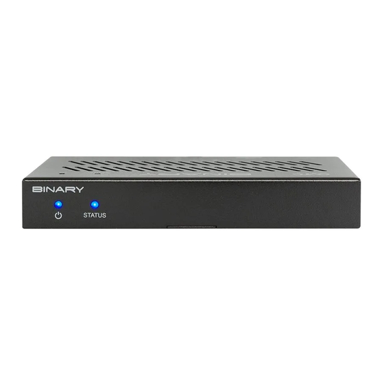
GETTING STARTED To get started, you need: • 1× per source: MoIP Transmitter • 1× per display: MoIP Receiver • 1× MoIP Controller B-900-MOIP-4K-CTRL • 1× Layer 2 Managed switch • Sources, Displays, HDMI cables and category cabling MoIP Controller B-900-MOIP-4K-CTRL B-900-MOIP-4K-CTRL CONTROLLER Network... - Page 5 MoIP Transmitter B-900-MOIP-4K-TX A. Power Indicator On: Power on | Blinking: Booting | Off: Power off B. System Status Light On: Connected to network with source present | Off: Not connected to network | Blinking: Connected to network and no source present. C.
- Page 6 MoIP Transmitter B-900-MOIP-4K-TX-2AC A. Power Indicator On: Power on | Blinking: Booting | Off: Power off B. System Status Light On: Connected to network with source present | Off: Not connected to network | Blinking: Connected to network and no source present. C.
- Page 7 MoIP Audio Transmitter B-900-MOIP-AUDIO-TX A. Power Indicator On: Power On | Blinking: Booting | Off: Power off B. System Status Light On: Connected to network with source present | Off: Not connected to network | Blinking: Connected to network and no source present. C.
- Page 8 MoIP Receiver B-900-MOIP-4K-RX A. Power Indicator On: Power on | Blinking: Booting | Off: Power off B. System Status Light On: Connected to network and not subscribed to transmitter stream | Off: Not connected to network | Blinking: Connected to network and subscribed to transmitter stream.
- Page 9 MoIP Receiver B-900-MOIP-4K-RX-2AC A. Power Indicator On: Power on | Blinking: Booting | Off: Power off B. System Status Light On: Connected to network and not subscribed to transmitter stream | Off: Not connected to network | Blinking: Connected to network and subscribed to transmitter stream.
- Page 10 MoIP Audio Receiver B-900-MOIP-AUDIO-RX A. Power Indicator On: Power on | Blinking: Booting | Off: Power off B. System Status Light On: Connected to network with source present | Off: Not connected to network | Blinking: Connected to network and no source present. C.
-
Page 11: Recommended Network Switches
This section details the networking requirements, recommendations and limitations when configuring a Binary B-900 Series Media over IP system (MoIP) system, which can be used to deploy MoIP on any compatible network switch. Included are steps to configure an Araknis 210 Series PoE and 310 Series PoE Layer 2 managed switch in a single switch MoIP deployment as well as basic guidelines, requirements for single and multiple switch MoIP setups. -
Page 12: Number Of Ports
• Forwarding Unknown Multicast to Multicast Router Port Only Number of Ports Given the flexibility and scalability of Binary’s B-900 Series Media over IP system, it is recommended that a switch with more Ethernet ports than needed for the MoIP system be used to allow quick addition of devices in the future. -
Page 13: Multiple Switches
MoIP System Network Setups Single switch MoIP network configurations are supported by Araknis 210 PoE and 310 PoE Series switches. Integrators familiar with the above requirements and the configuration of stackable and cascaded switches with multi-gigabit uplinks are able to create larger MoIP deployments. - Page 14 have no impact on available bandwidth. The bandwidth requirements of other devices on the network should also be considered. Each MoIP transmitter consumes 250-850 Mbps (4K) or 150-750 Mbps (1080p) of the available bandwidth. The lowest bandwidth link limitation applies no matter to which switch in the multiple switch setup the transmitter is connected.
-
Page 15: Network Troubleshooting
Network Troubleshooting It should be noted that for challenging network setups where complete isolation of a MoIP system is desired, the controller supports this functionality. A USB-to-Ethernet adapter with an ASIX 88179, ASIX 88178A, RealTek 8153, or RealTek 8152 chipset is required. Install this adapter before the MoIP controller is booted (or plug it in and restart). - Page 16 3. Verify Jumbo Frame SETTINGS > PORTS, then verify Jumbo Frame Choose is set to greater than 8,000 Bytes. The default value is 9216 the maximum is acceptable. 4. Set up the MoIP Controller Connect the controller to the MoIP Switch and use the external power supply to connect it to MoIP controller an AC outlet.
-
Page 17: Powering Up The System
5. Access Local UI using Remote Access 1. Log in to the MoIP Controller (default username/password is binary / binary). You are prompted to change the username and password upon first login. The user name and Configure> Account Management. password can be changed under the 2. - Page 18 9. Discover MoIP Transmitters and MoIP Receivers Access the local UI of the MoIP controller and click Discover to identify all transmitters and receivers on the system. Devices are discovered and assigned a transmitter or receiver number. Transmitter and receiver numbers correlate directly with the inputs or outputs for control system integration, similar to traditional matrix switchers.
- Page 19 10. Update TX and RX Firmware Once discovered, the controller automatically pushes firmware updates to the transmitters and receivers (if necessary). IMPORTANT: Do not remove any devices or restart until all have completed update status. 11. Identify Receiver-Display and Transmitter-Source Pairs (Recommended) 1.
- Page 20 12. Configure the MoIP Transmitters MoIP Video Transmitters 1. The audio EDID between the MoIP transmitter and the source can be fixed to 2 Channel Stereo or 5.1 Multichannel. By default, the device is shipped with this set to Pass-through. Pass-through allows all multi-channel high audio resolution formats including DTS-X, Dolby ATMOS, DTS HD Master Audio, and Dolby True HD.
- Page 21 Screenshot of B-900-MOIP-4K-TX Screenshot of B-900-MOIP-4K-TX-2AC...
- Page 22 MoIP Audio Transmitters 1. The Audio Resolution Sampling Frequency can be modified using the dropdown menu. Available Audio Resolutions include 16-bit or 24-bit, and the Sampling Frequency can be set to 48 kHz, 96 kHz, or 192 kHz. There are possible limitations on the ability for devices to receive audio, such as a receiving device using HDMI with its own limitations unknown to the MoIP system.
- Page 23 13. Configure the MoIP Receivers MoIP Video Receivers 1. For displays that only support 1080p and/or HDCP 1.4, set the corresponding receiver to match this requirement to allow video to pass. 4K video input into transmitters does not show on 1080p and/or HDCP 1.4 displays. 2.
- Page 24 Screenshot of B-900-MOIP-4K-RX Screenshot of B-900-MOIP-4K-RX-2AC 24 21...
- Page 25 MoIP Audio Receivers 1. The Maximum Output Level of the MoIP Audio receiver is adjustable to either 1 Volt or 2 Volts RMS. The proper setting is dependent on the amplifier or switcher/preamplifier that the receiver is connected to and the maximum voltage level that the line level input is capable of.
- Page 26 Create a Video Wall A video wall can be created with receivers currently discovered by the MoIP controller. After creating the wall, it’s added to the Receiver list alongside the existing receivers. 4x4, 3x3 and 2x2 video walls can be created out of 16, 9 and 4 receivers. Each receiver can only be a member of a single video wall group.
- Page 27 Set up Control System Integrating MoIP with your chosen control system is very similar to the steps to integrate a matrix switcher. The Binary team has developed custom drivers and worked with control system manufacturers to certify. The following control system drivers, models and documentation are available: Please refer to individual driver support documents for specific features and capabilities.
- Page 28 End User App • Visit Configure -> Client Control App Settings via the controller UI to enable client control outside of a control system. This allows clients to easily change input sources for each video display from their tablet or mobile device. Configure scenes to create common display templates (i.e.
-
Page 29: Two (2) Year Limited Warranty
Two (2) Year Limited Warranty Find details of this product’s 2-Year Limited Warranty at snapav.com/warranty, or request a paper copy from Customer Service at (866) 424-4489. Find other legal resources, such as regulatory notices and patent information, at snapav.com/legal. SUPPORT Need Help? Contact Tech Support! If you need further clarification, please call tech support at 866.838.5052, or email support@snapav.com. - Page 30 “Control4” and/or dba “SnapAV” in the United States and/or other countries. Snap AV and Binary are also registered trademarks or trademarks of Wirepath Home Systems, LLC. Other names and brands may be claimed as the property of their respective owners. All specifications subject to change without notice.
Need help?
Do you have a question about the B-900-MOIP Series and is the answer not in the manual?
Questions and answers