Sign In
Upload
Manuals
Brands
Dyna-Flo Manuals
Control Unit
571
Dyna-Flo 571 Manuals
Manuals and User Guides for Dyna-Flo 571. We have
2
Dyna-Flo 571 manuals available for free PDF download: Operation, Parts, And Instruction Manual
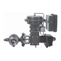
Dyna-Flo 571 Operation, Parts, And Instruction Manual (60 pages)
Brand:
Dyna-Flo
| Category:
Control Unit
| Size: 5 MB
Table of Contents
Table of Contents
1
General
2
Scope
2
Valve Dimensions - Table
2
Specifi Cations
3
Flange Stud Measuring Method - Figure
3
573 Valve Dimensions - Table
3
Flange Stud Lengths - Table
4
573 Flange Stud Lengths - Table
5
Flange Stud Diameters - Table
6
Flange Stud Quantity - Table
7
Mounting Pad Dimensions - Tables 8
8
Unpacking
9
Installation / Actuator Mounting
10
Periodic Inspection
13
Maintenance
13
Mounting Styles and Positions - Table
14
Actuator Removal
14
Disassembly
15
Packing Removal
15
Ball Seal Removal
16
Ball and Shaft Removal
18
Bearing Removal
23
Bearing Driver Construction Dimensions
25
Assembly
26
Bearing Installation
26
Ball / Shaft Installation
27
Packing Installation
35
Ball Seal Installation
40
To 12 Inch Ball / Shaft Connection
46
Parts
52
Model Builder
60
Advertisement
Dyna-Flo 571 Operation, Parts, And Instruction Manual (36 pages)
Brand:
Dyna-Flo
| Category:
Control Unit
| Size: 1 MB
Table of Contents
Table of Contents
1
General
2
Scope
2
570 Valve Dimensions - Table
2
Specifi Cations
3
Flange Stud Measuring Method - Figure
3
Valve Assembly / Dimensions - Figure
3
571 / 573 Valve Dimensions - Tables
3
Mounting Pad Dimensions - Table
4
Mounting - Figures
5
Follower Shaft Pin Diagram - Figure
7
570 Flange Stud Lengths - Table
8
Unpacking
8
Installation
8
Ball Seals - Figure
8
571 / 573 Flange Stud Lengths - Table
9
Periodic Inspection
9
Packing Maintenance
9
Disassembly
9
Ball / Pin Diagrams - Figure
9
Flange Stud Diameters - Table
10
Valve / Actuator
10
Packing Removal
10
Ball Seal Removal
10
Flange Stud Quantity - Table
11
Ball / Shaft / Bearings
11
Bearing Diagram - Figure
11
Bearing Removal
12
Dyna-Flo Control Valve Services Ltd
12
Assembly
12
Bearing Assembly
12
Mounting Styles and Positions - Table
12
Ball / Shaft
13
Packing
13
Bearing Driver Tool - Figure 10 / Table
13
570 Cross Section - Figure 12 and
13
Ball Seal
14
Actuator Mounting
14
571 / 573 Cross Section - Figure
14
Packing - Figure
15
Drive Shaft Pin Installation
25
Follower Shaft Pin Installation
26
Ball / Shaft Assembly
27
Parts
29
Model Builder
36
Advertisement
Related Products
Dyna-Flo 570
Dyna-Flo 573
Dyna-Flo 590
Dyna-Flo 5000
Dyna-Flo 350
Dyna-Flo 350H
Dyna-Flo 351
Dyna-Flo 351H
Dyna-Flo 360
Dyna-Flo 360A
Dyna-Flo Categories
Control Unit
Controller
More Dyna-Flo Manuals
Login
Sign In
OR
Sign in with Facebook
Sign in with Google
Upload manual
Upload from disk
Upload from URL