Table of Contents
Advertisement
Quick Links
Advertisement
Table of Contents

Related Manuals for Tektronix 2221A


Summary of Contents for Tektronix 2221A
- Page 1 User Manual T ektronix 2221A Digital Storage Oscilloscope 070-8156-02...
- Page 2 Instrument Serial Numbers Each instrument manufactured by Tektronix has a seriai number on a panel insert or tag, or stamped on the chassis. The first letter in the serial number designates the country of manufacture. The last five digits of the serial number are assigned sequentially and are unique to each instrument.
- Page 3 Tektronix, with shipping charges prepaid. Tektronix shall pay for the return of the product to Customer if the shipment is to a location within the country in which the Tektronix service center is located.
- Page 4 This apparatus has been designed and tested in accordance with IEC Publication 348, Safety Requirements for Electronic Measuring Apparatus, and has been supplied in a safe condition. This manual contains some information and warnings which have to be followed by the user to ensure safe operation and to retain the apparatus in safe condition.
- Page 5 BQ10100 to B019999; and part number 070-8549™XX is for serial numbers B020000 and above. ■ The 2221A, 2224, & 2232 Optional GPIB & RS-232-C Interfaces User Manual (070-8159-XX) shows how to connect, program, and use the optional GPIB and RS-232-C communication interfaces.
- Page 6 Welcome...
-
Page 7: Table Of Contents
Save Reference Memory Buttons ..-----. . . ------- — . 2-22 Setup M enus....2-25 Acquisition Menu ..2-26 Display M en u ....— 2-28 Plot Menu ........— 2-29 Advanced Functions Menu ....2-30 2221A User Manual... - Page 8 Triggering on Low-Frequency Signals ........3-26 Triggering on Random or Infrequent Events ......3-26 Triggering on Complex or Non-Repetitive Signals ....3-27 Triggering on Line Frequency............ 3-27 Triggering with an External Signal ......3-28 Triggering on TV Signals ..3-28 2221A User Manual...
- Page 9 Appendix B: Specification ............General Product Description........Options and Accessories............ Performance Conditions......Characteristic Tables ......Appendix C: Performance Verification ......A-25 General Information ..........A-25 Purpose.................. A-25 Performance Check Interval ..........A-25 Structure..................A-25 Limits and Tolerances..............A-25 2221A User Manual...
- Page 10 Horizontal System Checks .... A-37 Trigger System Checks ............A-43 External Z-Axis, Probe Adjust, External Clock, and X-Y Plotter Checks ............A-49 Appendix D: Storage Modes ......A-53 Glossary and Index Glossary ....... In d e x ....2221A User Manual...
- Page 11 Figure 3-6: Scan Mode ......3-11 Figure 3-7: Roll Mode ............— 3-12 Figure 3-8: Accumulate Peak Mode Display ........3-13 Figure 3-9; Peak Detect Mode D isplay..........3-14 Figure 3-10: Average Mode Display ........3-14 2221A User Manual...
- Page 12 3-47 Figure A-1; Maximum input voltage versus frequency derating curve for the CH 1 OR X, CH 2 OR Y and EXT INPUT connectors..A-21 Figure A-2: Physical dimensions of the 2221A Digital Storage O scilloscope........A-24 2221A User Manual...
- Page 13 A-30 Table A-9: Storage Deflection Accuracy..........A-31 Table A-10: Settings for Bandwidth Checks........A-33 Table A-11: Settings for Timing Accuracy Checks ......A-39 Table A-12: Switch Combinations for Triggering Checks....A-44 Table A-13: Storage Modes .............. A-53 2221A User Manual...
- Page 14 2221A User Manual...
-
Page 15: Product Description
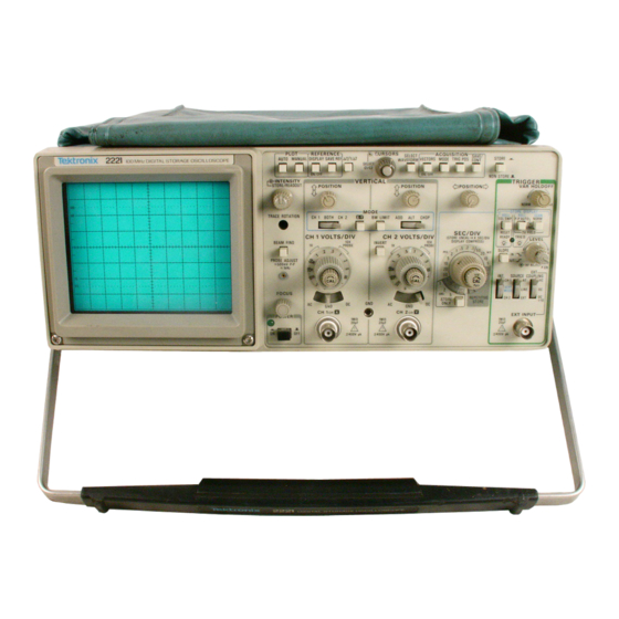
Product Description Your Tektronix 2221A Digital Storage Oscilloscope is a superb tool for displaying, measuring and saving waveforms, its performance addresses the needs of both benchtop lab and portable applications: Combination analog and digital oscilloscope ■ 100 MHz maximum analog bandwidth ■... - Page 16 Product Description...
-
Page 17: Safety
DANGER indicates a personal injury hazard immediately accessible as one reads the marking. This symbol appears in manuals: ® Static-Sensitive Devices These symbols appear on equipment: ATTENTION DANGER Protective High Voltage ground (earth) Refer to terminal manual 2221A User Manual... -
Page 18: Specific Precautions
Do not operate the 2221A in an atmosphere of explosive gasses. Electric Overload Never apply a voltage to a connection on the 2221A that is outside the range specified for that connection. Do not attempt to operate the oscilloscope without a proper ground connection. -
Page 19: Start Up
Figure 1-1: Installing the Power Cord |~| Step 2: Check that you have the proper power supply for the instru ment. The 2221A requires a line source that is 90 to 250 VAC with a frequency of 48 Hz to 440 Hz. -
Page 20: Initial Setup
□ Step 3: Check the fuse to be sure it is the proper type and rating. The 2221A is shipped with the UL® approved fuse installed. ("1 Step 4: Be sure you have the appropriate operating environment. Specifications for temperature, relative humidity, altitude, vibrations, and emissions are included in the Specifications appendix of this manual. -
Page 21: Adjusting Trace Rotation
["I Step 2: Using a small-blade screwdriver, adjust the recessed TRACE ROTATION control to align the trace with the graticule line. You may need to make this adjustment again if you move or orient the oscilloscope in a different direction. 2221A User Manual... -
Page 22: Checking The Probe Compensation
Checking the Probe Compensation NOTE Always compensate a probe for the particular channel that you use it with. Use the following procedure to check the probe compensation: Step 1: Set the instrument controls as described in Setting up the Display. §tep 2: Connect the probe to the channel you intend to use it for. -
Page 23: Installing The Accessory Pouch
Figure 1-4 shows the correct method of installing the accessory pouch on Installing the the instrument. Accessory Pouch C. Bow the Plate and Slide it into the Front Trim Gap. Figure 1-4: Installing the Accessory Pouch 2221A User Manual... -
Page 24: Using The Power Cord Wrap
o u i r i u p Using the Power Figure 1 -5 shows how to wrap the power cord on the back when you trans port or store the instrument. Cord Wrap Figure 1-5: Using the Power Cord Wrap Before You Begin... -
Page 25: Front Panel
(Figure 2-1): Display Controls, Cursor Controls Display Mode page 2-8. page 2-20. Select Button, Figure 2-1: Front Panel Control Sections Figures 2-2 and 2-3 show the front panel of the oscilloscope in greater detail. 2221A User Manual... -
Page 26: Figure 2-2: Front Panel View - Left Side
Front Panel CRT D isplay Figure 2-2: Front Panel View — Left Side At a Glance... - Page 27 Front Panel « f Display Mode Store (digital) Non-Store (analog) Trigger Vertical Controls Horizontal Controls Controls Figure 2-3: Front Panel View — Right Side 2221A User Manual...
-
Page 28: Figure 2-4: Power Switch
Front Panel Switch POWGT The Power switch is shown in Figure 2-4. POWER Figure 2-4: Power Switch POWER The push-button switch turns the power on and off. A green Sight indicates the power is on. At a Glance... -
Page 29: Crt Display
LJ3i_ _ 6“ 1 ....-A ,l"J Percent Markings are for rise time measurements. Each major division is split into 5 minor divisions. One minor division equals two-tenths (.2) of a major division. Figure 2-5: CRT Graticule 2221A User Manual... -
Page 30: Display Mode
Front Panel There are two separate display modes; the analog NON-STORE mode Display Mode (Figure 2-6) and the digital STORE mode (Figure 2-7). The STORE/NON- STORE button selects the display mode. © j 0 G jg L o « © ©... -
Page 31: Figure 2-7: Digital (Store) Mode Display
(GPIB or RS-232). A similar symbol under the SREF readouts 1, 2, 3, 4K (refer ence memories) or A (current acquisition) indicates which of these waveform displays is currently selected for cursor measurement. 2221A User Manual... -
Page 32: Crt Display Controls
Front Pane! CRT Display Controls *I"he display controls (Figure 2-8) adjust the alignment, intensity and focus of the waveform displays and readout information. Figure 2-8: CRT Display Controls At a Glance... - Page 33 Aligns baseline trace with the horizontal graticule. (Use a small screwdriver to adjust the recessed control.) INTENSITY STORE/READOUT Adjusts the intensity of the entire STORE display as well as NON-STORE readouts. GRATICULE Controls graticule illumination. FOCUS Focuses the display. BEAM FIND Locates dim or off-screen displays. 2221A User Manual...
-
Page 34: Vertical Controls And Connections
Front Panel < * Vertical Controls and Figures 2-9 and 2-10 show the vertical controls and connections. Connections Figure 2-9: Vertical Controls and Connections 2-10 At a Glance... - Page 35 Channel 2 saved waveforms, CAL (Channel 2) (Calibrated) — The clockwise position provides calibrated voits/division settings. Rotating the control counterclockwise variably increases the attenu ation of the settings, thereby reducing signal amplitude. (Variable settings are not calibrated.) 2-11 2221A User Manual...
-
Page 36: Figure 2-10: Vertical Controls And Connections (Cont.)
rro m ranei Vertical Controls and Connections (Cont.) Figure 2-10: Vertical Controls and Connections (Cont.) 2-12 At a Glance... - Page 37 BOTH — Activates the ADD ALT CHOP switch for two-channel displays. CH 2 — Displays Channel 2 oniy. 17. PRB ADJ (Probe Adjust) — Provides a 0.5 V square wave signal to compensate X I0 probes. 2-13 2221A User Manual...
-
Page 38: Horizontal Controls
Front Panel Horizontal Controls The horizontal controls are shown in Figure 2-11. Figure 2-11; Horizontal Controls 2-14 At a Glance... - Page 39 The clockwise position selects calibrated settings. In STORE, rotating the control counterclockwise horizontally compresses 4K acquisitions to 1K. X I0 (STORE ONLY) Slows the STORE sweep speeds of 0.1,0.2, and 0.5 seconds to 1,2, and 5 seconds respectively. 2221A User Manual 2 -7 5...
-
Page 40: Trigger Controls
Front Panel Trigger Controls Figure 2-12 and Figure 2-13 illustrate the trigger controls. Figure 2-12: Trigger Controls 2-76 At a Glance... - Page 41 AC — Capacitively couples (and blocks DC components) of the signal. DC — Couples DC and all other signal components. DC/10 — Couples all signal components and attenuates the external input signal by a factor of 10. EXT INPUT Input connection for an externa! trigger signal. 2-17 2221A User Manual...
-
Page 42: Figure 2-13: Trigger Controls (Cont)
Front Panel Trigger Controls (Cont.) ai O °E □ O O G o. 1 g o g O r ‘ S 1 rh © ¥ § ) ! i 1 1 o 1*=* | (© > ■ s . Figure 2-13: Trigger Controls (Cont) At a Glance 2-18... - Page 43 10. SGLSWP (Single Sweep) — Sets the oscilloscope to trigger a single sweep in the NON-STORE mode. In the STORE mode, single-shot events are captured and displayed. 2 -1 9 2221A User Manual...
-
Page 44: Cursor Controls
Front Panel Cursor Controls The cursor controls are shown in Figure 2-14. Figure 2-14: Cursor Controls CURSORS Rotating the CURSORS knob moves the selected cursor. The IK window of a 4K acquisition will move with the selected cursor to view the entire record. (The CURSORS control can also make item selections or change item values in the ACQ and REF Setup menus.) SELECT C1/C2 (PUSH) —... -
Page 45: Acquisition Controls
(Trigger Position) — Selects the acquisition record displayed relative to the trigger position (indicated by a “T”) on the waveform; pretrigger, midtrigger, or posttrigger. SAVE/CONT (Save or continue) — SAVE temporarily freezes and displays the current acquisition record. CONT (continue) starts another acquisition. 2-21 2221A User Manual... -
Page 46: Save Reference Memory Buttons
n u i i i rant!! The Save Reference Memory buttons are shown in Figure 2-16. Save Reference Memory Buttons Q % * ■ • SAVE REF Q ON/OFF___1 Figure 2-16: Save Reference Memory Buttons SAVE REF 1,2, 3 or SAVE REF 4K — When waveforms are displayed in the STORE mode, you can use the buttons to save up to three separate displays acquired in the 1K mode (memory locations 1, 2 or 3) or one dis... -
Page 47: Figure 2-17: 1K Two-Channel Acquisition, Memory Location 1
The “— 'H underneath 1 indicates the cursors are on this memory display. Figure 2-17: 1K Two-Channel Acquisition, Memory Location 1 Indicates SAVE REF Memory location 4K. Figure 2-18: 4K Two-Channel Acquisition, Memory Location 4K 2 -2 3 2221A User Manual... - Page 48 2-24 At a Glance...
-
Page 49: Setup Menus
For example, pressing the DISPLAY setup button brings up the Display Menu (Figure 2-20). Pressing the button underneath AT Display selects either AT or 1 / AT. 2-25 2221A User Manual... -
Page 50: Acquisition Menu
a e iu p m enus A Time Selected Menu Item Select “Bezel” Buttons Figure 2-20: Setup Menu Example (Display) The Acquisition menu (Figure 2-21) allows you to configure the acquisition Acquisition Menu system to your particular application. ----------------------------------------------------------------- ACQUISIT Push SET! JP A CQ Button to exit L . - Page 51 Avg Wgt (Average Weight) — Weights the last sample in the Average ac quisition mode from 1/1 to 1/256. Swp Lim (Sweep Limit) — Selects the number of acquisitions to make before halting; 1 to 999,000 or NO LIMIT. 2-27 2221A User Manual...
-
Page 52: Display Menu
WGIU|/ The Display menu allows you to configure cursor time readout, smoothing Display Menu and vectors (Figure 2-22). ISPL RFTiJJE LD LSEL AYE L U ffQ J i to exit. Air V 1 kT ■irr A _ T Dis play Smoothj Vector SAVE REF , ON/OFF. -
Page 53: Plot Menu
Auto Plot ON — Automatically plots acquisitions. The graticule and readouts are plotted on the first acquisition only. The oscilloscope will wait for each plot to finish before beginning another acquisition. OFF — Disables Auto Plot. 2221A User Manual 2-29... -
Page 54: Advanced Functions Menu
Figure 2-24: Advanced Functions Menu Diag Menu (Diagnostic Menu) — Selects diagnostic tests and calibration aids used to service the instrument Detailed menu information is contained in the 2221A service manual. Comm Menu (Communications Menu) — - Sets stop-bit and flow parameters for the RS-232 option. -
Page 55: Figure 2-25: Save Setup Menu
Setup2 — The oscilloscope uses the settings saved under “Setup2” at power up. Select Setup Setupl — Selects “Setupl ” to save to, or recall from, memory. Setup2 — Selects “Setup2" to save to, or recall from, memory. 2-31 2221A User Manual... - Page 56 o tn u jj ivicnus & Recall Setup Recalls the indicated Select Setup memory. Save Setup Saves the current software-controlled settings to the indicated Select Setup memory. 2-32 At a Glance...
-
Page 57: Displaying Signals
Displaying Signals Displaying Signals describes the basic tasks involved in using the 2221A Digital Storage Oscilloscope to reveal the waveform characteristics of electri cal signals. In particular, Building a Basic Display, provides an overview of the control sections and is a good starting point for anyone unfamiliar with oscilloscopes. -
Page 58: Coupling Signals
If necessary, use a termination (usually 50 Q) on the signal input to match the characteristic impedance and preserve the fidelity of the signal. Tektronix also carries a variety of coaxial cable and cabling accessories for various applications. -
Page 59: Building A Basic Display
■ Trigger These control sections are arranged left to right across the front panel of the 2221A Digital Storage Oscilloscope. Presetting the Controls It is often helpful to preset the front pane! controls to get a sweep on the screen before you try to apply a signal. With a simple “trace” on screen you can adjust the display intensity and focus before you make any other set... -
Page 60: Selecting The Trigger Mode
Displaying Signals As soon as you enter the STORE mode the oscilloscope digitally acquires the signal and actively displays it on the screen. Acquisition modes for different sweep speeds are determined by default but they may be changed. (Refer to Digitizing Signals, page 3-8.) The front panel controls that govern the analog display in NON-STORE also govern the storage display. -
Page 61: Selecting The Vertical Mode And Scale
BOTH — Activates the ADD ALT CHOP switch for two-channel displays. CH 2 — Displays Channel 2 only. Step 2: Preset the input coupling for that channel to ground (GND). (Also refer to Precharging the Signal input, page 3-2.) 2221A User Manual... -
Page 62: Setting The Display Intensity And Focus
20 mV to 50 V per division for a 10X probe. (Probes with higher factors of attenuation are also available from Tektronix.) If a probe is properly coded, the display readout of the channel it is connected to will change by the appropriate scale factor. -
Page 63: Finding "Lost" Displays
|~1 Step 2: Set the oscilloscope in the NON-STORE mode. |~| Step 3: Press the BEAM FIND button and hold it in. The beam of the CRT is now intensified and compressed into the viewing area (Fig ure 3-5). 2221A User Manual... -
Page 64: Digitizing Signals
wiatjjieiyiiiy 0 *9 na,B BEAM FIND Figure 3-5: Beam Find if the beam appears to be stuck on some portion of the display, check the trigger mode settings. Setting the trigger mode to P-P AUTO wiil give you a sweep in the absence of a trigger signal. Also check to be sure the X-Y button is not pushed in and the seconds/division is not set too fast or too slow for the signal you are trying to display. -
Page 65: Selecting The Acquisition Mode
The oscilloscope overwrites the record left to right with new data only when there is another trigger. Triggered Scan Mode is useful for capturing single, slowly occurring events coincident with a trigger. 3 -9 2221A User Manual... -
Page 66: Viewing Slowly Occurring Events
u is f jia y m y o ig n s is & ■ Scan-roll-scan — (SGL SWP and Scan) A new record appears across the screen from left to right until it reaches the trigger point and then rolls right to left from the trigger point until a trigger occurs. When a trigger occurs, the oscilloscope scans left to right until the record is filled and then freezes the display. - Page 67 I I Step 3: Select Roil and press the ACQ menu button again to exit the menu. Step 4: Note that the trace “rolls" across the screen from right to left {Figure 3-7) and does not permit any trigger event to interrupt the dis play. 2221A User Manual 3-11...
-
Page 68: Capturing Random Events
Displaying.Signals Current Data Capturing Random Events Infrequent or random events can be “captured” by using the single-sweep trigger mode in combination with either the Scan or the Roll mode. These two modes are called “Scan-roii-scan" and “Triggered Roll" respectively. These two modes are only available at sweep speeds of 0.1 ms and slower. Triggered Roll: F I Stepl: Set the Trigger Mode to P-P AUTO. -
Page 69: Accumulating Signal Peaks (Accpeak)
AVERAGE mode is best. Refer to Averaging Signals, page 3-14.) While ACCPEAK gives the best view of signal glitches overtime, PEAKDET mode is the best default mode (for sweep speeds of and slower) because it automatically captures signal spikes and pres- 3-13 2221A User Manual... -
Page 70: Averaging Signals
LMspiaymg signals « r ersts a truer view of the signal. Figure 3-9 shows how the signal in Figure 3-8 appears in the Peak Detect mode. Notice that the noise and glitches are detected, but not accumulated in Peak Detect. Figure 3-9: Peak Detect Mode Display Averaging Signals The AVERAGE mode (Figure 3-10) is excellent for visually eliminating ran... -
Page 71: Clocking Acquisitions
Step 2: Position the active cursor one way or the other to view the rest of the acquisition record. (Note that the active cursor and the display window indicator also move along the acquisition window indicator Display Window Indicator Inactive Cursor Figure 3-12: Acquisition Window Indicator 3-15 2221A User Manual... -
Page 72: Compressing The Acquisition Record Length (4K Compress)
w w p i u y i f t y v i ^ n a c o Compressing the Acquisition Record Length (4K Compress) You can compress a 4K acquisition to one screen. However only 1,024 data points are displayed. F I Step 1: Go to the STORE mode and display the signal in the 4K mode (Figure 3-13). -
Page 73: Positioning The Acquisition Record
Pretrigger {Figure 3-15) Midtrigger {Figure 3-16) ■ Posttrigger {Figure 3-17) 1 =0 0 = D . ii S [ y • " " P E PSCDI : T Figure 3-15: Pretrigger Acquisition Figure 3-16: Midtrigger Acquisition 3-17 2221A User Manual... -
Page 74: Preventing Signal Aliases
Displaying Signals T R : = D . S u j £ U / v A ft ■ v i a m o i i Figure 3-17: Posttrigger Acquisition The trigger position is also “point selectable.” This means that the trigger point can be positioned anywhere along the acquisition record. -
Page 75: Displaying Magnified Sweeps
STORE mode: l~1 S te p l: Position the sweep until the portion of the sweep you want to magnify is centered horizontally on the display. Step 2: Pull out the X I0 CAL PULL knob. 3-19 2221A User Manual... -
Page 76: Displaying Two Channels
L/ispiaymg oigrmis □ Step 3: Adjust the horizontal position control as necessary to center the display. Perform the following procedure to use the X I0 magnifier in the STORE mode: Step 1: Center the active cursor on the portion of the sweep you want to magnify. -
Page 77: Figure 3-19: Rejecting Common Mode Signal
Channel 1 and Channel 2 POSITION controls. Channel 1 signal with undesired component Channel 2 with undesired AC component inverted Channel 1 and Channel 2 (invert) in the ADD Mode. Undesired AC component is canceled. Figure 3-19: Rejecting Common Mode Signal 3-21 2221A User Manual... -
Page 78: Displaying X-Y Patterns
Phase and frequency relationships between two signals can be viewed in Displaying X-Y the X-Y mode by pressing the X-Y button on the front panel (Figure 3-20). Patterns MODE y (CH 2) I M I . I I I I 1 W ..I* * -— I —... -
Page 79: Figure 3-21: X-Y Phase Relationships
Frequency of the signal applied to X axis is twice that of the signal applied to the Y axis. Frequency of the signal applied to Y axis is twice til at of the signal applied to the X axis. Figure 3-22: X-Y Frequency Relationships 3-23 2221A User Manual... -
Page 80: Limiting Bandwidth
Displaying Signals High-frequency noise from extraneous sources can sometimes interfere with Limiting Bandwidth a signal display. Push in the BW LIMIT button on the front panel to limit the BW LIMIT vertical response of the scope to frequencies below 20 MHz. A “ BWL” read out will also appear on the display. -
Page 81: Triggering On Signals
["I Step 4: Set the COUPL switch to NORM. [~1 Step 5: Adjust the TRIGGER LEVEL, if necessary, to stabilize the display, □ SteP 6; Adjust the vertical and horizontal controls to display a few cycles of the waveform. Figure 3-24: Repetitive Sine Wave 3-25 2221A User Manual... -
Page 82: Triggering On Low-Frequency Signals
Triggering on Low-Frequency Signals Use the NORM trigger mode for signals that are lower than 20 Hz in NON STORE or 500 Hz in STORE. If the repetitive signal is lower than these frequencies, the P-P AUTO circuit interferes with obtaining a stable trigger. This is because the P-P AUTO circuit will start to generate its own signal to trigger a sweep or acquisition. -
Page 83: Triggering On Complex Or Non-Repetitive Signals
Refer to Selecting the Acquisition Record Length (1KI4K), page 3-15. Triggering on Line Frequency To trigger on power line signals, apply the signal to an input and move the COUPL switch to LINE SOURCE. 2221A User Manual 3-27... -
Page 84: Triggering With An External Signal
LMspiaymg signals Triggering with an Externa! Signal Trigger one- or two-channel displays with an externally applied signal using the following procedure: □ Step 1: Apply the external signal to the EXT INPUT connector using a coaxial cable. □ Step 2: Set the SOURCE to EXT □... -
Page 85: Removing Unwanted Trigger Signal Components
COUPL switch to either HF REJ or LF REJ. The HF REJ position attenuates trigger signal components above 40 kHz and the LF REJ position attenuates trigger signal components below 40 kHz. 3-29 2221A User Manual... - Page 86 lo piayiiiij 3-30 Detail...
-
Page 87: Measuring Signals
Cursor measurements are highly accurate and eliminate the calculations of Measuring with graticule measurements. In STORE mode the oscilloscope simultaneously STORE Mode displays the voltage and time difference between the cursor pair. Using the Cursors DISPLAY menu you can also measure frequency by selecting 1/AT. 3-31 2221A User Manual... -
Page 88: Positioning The Cursors
Measuring Signals Positioning the Cursors A cursor is either active or inactive. A box surrounds the active cursor to CURSORS SELECT WAVEFORM signify that it can be positioned by the CURSORS knob. The inactive cursor does not have a box around it and will stay fixed while you position the other cursor {Figure 3-30). -
Page 89: Measuring Voltages In Reference To G Round
The oscilloscope will now recognize this point as ground and place a small dot at the left side of the screen. (This dot may not be readily apparent if you have a fiat line trace on screen.) F I Step 3: Set the input coupling to DC. 3-33 2221A User Manual... -
Page 90: Figure 3-32: Dc Component Of Ac Signal
Measuring signals □ Step 4: Move one of the cursors over to the left side of the display. When this cursor aligns with the ground reference dot the A symbol next to the volts readout changes to a ground symbol (Figure 3-32 and Figure 3-33), □... -
Page 91: Measuring Time With The Graticule Or Cursors
Step 5: Note the A time (change or difference in time) readout in the upper right corner of the display. 3-35 2221A User Manual... -
Page 92: Measuring Frequency
ivicd^uring oiynais Figure 3-35 shows a typical period measurement Figure 3-35: Period Measurement Measuring Frequency Frequency is measured by calculating the inverse of a period measurement (1/AT). With a graticule measurement you would have to calculate this yourself. Using the Display menu, however, you can set the STORE mode cursors to display the frequency: Step 1: Press the Setup DISPLAY button on the front-panel. -
Page 93: Measuring Rise Time And Fail Tim E
4 1 = 1 0 2 , 5 r i s iS fiU E |y !V J f i U F R f l k 5 3 n s > 8 j s U Figure 3-37: Measuring Rise Time 3-37 2221A User Manual... -
Page 94: Measuring Trigger Level
ensuring otgnais i v i AT = 17 2 . 0 r 15 A V I = 8 1 . 0 * TR : = B 2 * . “ pT " / i r ~ " v ■ s u E R fiG E >... -
Page 95: Figure 3-39: Measuring Phase Difference
45° (Figure 3-39). Channel 1 Reference Channel 2 Figure 3-39: Measuring Phase Difference For higher resolution measurements of the phase difference the display may be magnified horizontally by pulling the X I0 magnification knob out (Figure 3-40). 2221A User Manual 3-39... -
Page 96: Figure 3-40: Phase Difference In X I0 Magnification
Measuring signals Channel 2 Channel 1 Reference X I0 Mag Figure 3-40: Phase Difference in X I0 Magnification 3-40 In Detail... -
Page 97: Saving Waveforms And Setups
STORE mode setup configurations. Saving and Recalling With the 2221A oscilloscope you can “freeze” a waveform with the touch of a button. You can also keep a waveform for later reference by using a SAVE Waveforms REF memory location. -
Page 98: Recalling A Waveform From Save Ref
J Q v m y vy c iv e t u r n is a n t i o e i u p s Figure 3-41: SAVE REF Memory Buttons Recalling a Waveform from SAVE REF Once a waveform is stored in a SAVE REF memory location, simply press the memory location button to recall or remove it from memory. -
Page 99: Recalling A Setup From Memory
Setupl — The instrument will use the setup saved under Setupl at power Setup2 — The instrument will use the setup saved under Setup2 at power f l Step 4: The selection is now saved. Press the ADV FUNCT button to return to normal operation. 3-43 2221A User Manual... - Page 100 Saving Waveforms and Setups 3-44 En D e ta il...
-
Page 101: Transmitting Waveforms
(Only one interface can be installed in the instrument at a time.) The two interface options are depicted in Figure 3-42 and Figure 3-43. The 2221A, 2224, & 2232 Optional GPIB & RS-232-C Interfaces User Manual (070-8159-01) provides you with information about connecting the GPIB and RS-232-C communication options to external printers, plotters, or computer ports. -
Page 102: Plotting Or Printing A Waveform
Transmitting Waveforms PARAMETERS I A U X IL IA R Y C O N N E C T O R I R E L A Y N .O . RELAY COMM j---- Ht J h2 " i +4.2 VDC SIG GND ADDR - 1 8 LF OR EQI... -
Page 103: Figure 3-45: Plot Menu
Transmitting Waveforms & The 2221A, 2224, S t 2232 Optional GRIB & RS-232 Interfaces User Manual (070-8159-01) provides you with information about using either interface option to drive a printer or plotter. Plot Menu The Plot menu (Figure 3-45) allows you to control and initiate the plot. Each item on the menu is described below. - Page 104 Transmitting Waveforms & Auto Plot ON — Automatically plots acquisitions. The graticule and readouts are plotted on the first acquisition only. The oscilloscope will wait for each plot to finish before beginning another acquisition. OFF — Disables Auto Plot. XY Setup XY Setup generates a pattern for calibrating analog X-Y plotter gain and offset.
-
Page 105: Appendix A: Options And Accessories
IEEE Standard Digital interface for Programmable Instrumentation (ANSI/IEEE Std 488—1978). It also complies with a Tektronix Standard relat ing to GPIB Codes, Formats, Conventions and Features. The 2221A, 2224, & 2232 GPIB & RS-232-C Optional Interfaces User Manual {070-8159-x x ) provides operating information for the Option 10 GRIB interface. -
Page 106: Table A-2: Standard Accessories
The Travel Line option can be installed on existing instruments by ordering the Travel Line kit (040-1202-04). OPTION 3R: Rackmount Option 3R allows you to mount the 2221A into a standard 19 inch equipment rack. S t a n d a r d... -
Page 107: Other Accessories
C9, Option 20 Camera Portable Instrument Cart K212 QuickStart Training Aid (U.S.) 0 2 0 -1 812-04 QuickStart Training Aid (International) 0 2 0 -1 812-06 S41SAVE WaveSaver Software HC100 Opt 03 HCtOO Plotter RS-232 HC100 Opt 01 GPiB 2221A User Manual... - Page 108 Appendix A: Options and Accessories Appendices...
-
Page 109: Appendix B: Specification
2221A Digital Storage Oscilloscope. Characteristic Tables, lists instrument characteristics of the oscilloscope in detail and the requirements that corre spond to them. The TEKTRONIX 2221A Digital Storage Oscilloscope is a portable, dual General Product channel oscilloscope suitable for use in a variety of test and measurement Description applications. - Page 110 Appendix b: specification ■ Glitch-catching capabilities for glitch widths as narrow as 10 ns ■ Acquisition of waveforms in any of four acquisition modes: SAMPLE, AVERAGE, ACCPEAK, and PEAKDET (peak detect is available only at SEC/DIV settings slower than 2 ps) m Maximum stored record lengths per waveform of either 4096 bytes (4 K) for single-channel acquisitions or 2048 bytes (2 K) for dual-channel acquisitions (ALT or CHOP}...
-
Page 111: Options And Accessories
Options and Accessories which begins on page A-1 of this Accessories manual. Your Tektronix representative, local Tektronix Field Office, or Tektro nix products catalog can also provide additional accessories information. The following electrical characteristics (Table A-4) are valid when the instru... -
Page 112: Characteristic Tables
Appendix B: Specification Characteristic Tables The characteristics listed in the tables that follow are valid when the perfor mance conditions just listed are met. Items listed in the “Performance Re quirements" column are verifiable qualitative or quantitative limits that define the measurement capabilities of the oscilloscope. - Page 113 PEAKDET or ACCPEAK with SMOOTH SEC/DIV setting x 1.6 SEC/DIV setting x 1.6 Rise time is limited to 3.5 ns minimum with derating over temperature (see NON-STORE Rise Time). 1 Performance requirement not checked in manual. A -9 2221A User Manual...
- Page 114 Table A-4: Electrical Characteristics (Cont.) Characteristics Performance Requirements Aberrations (NON-STORE and STORE in De fault Modes) 2 mV per division to 50 mV per division 4*4%, — 4%, 4% p-p 0,1 V per division to 0.2 V per division +6%, -6% , 6% p-p 0.5 V per division 4*6%, -6% , 6% p-p1 1 V per division to 5 V per division...
- Page 115 20 pF ± 2PF1 Capacitance 1 Performance requirement not checked in manual. 3One hundred MHz bandwidth derated for temperatures outside 0° C to +35° C and at 2 mV VOLTS/DIV setting as for NON-STORE. A -1 1 2221A User Manual...
- Page 116 M fjfjc rtu fx ; o p e u in u a u u ri * * ■ Table A-4: Electrical Characteristics (Cont.) Characteristics Performance Requirements Maximum Safe Input Voltage (CH 1 and See Figure A-1 on page A-21 for maximum input voltage ver sus frequency derating curve.
- Page 117 4Holdoff in STORE mode is a function of microprocessor activity and the pretrigger acquisition. The VAR HOLDOFF control main tains some control over the STORE hoidoff by preventing a new trigger from being accepted by the storage circuitry until the next (or current, if one is in progress) NON-STORE hoidoff has completed. 2221A User Manual A-13...
- Page 118 Mppenaix e: opecm cauon Table A-4: Electrical Characteristics (Cont.) Characteristics Performance Requirements Midtrigger One-half of the waveform acquisition window is prior to the trigger {other trigger points are selectable via the MENU). One-eighth of the waveform acquisition window is prior to the Post Trigger trigger (other trigger points are selectable via the MENU).
- Page 119 Logic Thresholds are TTL compatible. 25 V (DC + peak AC) or 25 V p_ p AC at 1 kHz or less.1 Maximum Safe input Voitage ^ Input Resistance Greater than 3.5 kO (LSTTL compatible).1 Performance requirement not checked manuai. A-15 2221A User Manual...
- Page 120 Mppenaix ^pecmcauon Table A-4: Electrical Characteristics (Cont.) Performance Requirements Characteristics STORE Mode Resolution Acquisition Record Length 1024 or 4096 data points.1 Single Waveform Acquisition Display 1024 data points (100 data points per division across the graticule area). CHOP or ALT Acquisition Display 512 data points (50 data points per division across the grati...
- Page 121 SAVE Mode Expansion Range (YT mode) 10 times as determined by the X I0 MAG switch. Expansion Accuracy Same as the Vertical.1 1 Performance requirement not checked in manual. A-17 2221A User Manual...
- Page 122 Appendix B: Specification Table A-4: Electrical Characteristics (Cont.) Characteristics Performance Requirements Digital Readout Display CURSOR Accuracy Voltage Difference ±3% of the AV readout value, ±0.4% of full scale (8 divisions). Applies within center 6 divisions. Time Difference RECORD or ROLL/SCAN SAMPLE or AVERAGE ±1 display interval.7 PEAKDET or ACCPEAK...
- Page 123 Fused relay contacts, 100 mA maximum.1 Output Voltage Levels 500 mV per division ±20%. Center screen is 0 V ±1 division. Measured with a DC-coupied, five-division reference signal. Series Resistance 2 kO ±10%1 1 Performance requirement not checked in manual. A-19 2221A User Manual...
- Page 124 Appendix B: Specification & Table A-4: Electrical Characteristics (Cont.) Characteristics Performance Requirements Power Supply Line Voltage Range 90 VAC to 250 VAC1 Line Frequency 48 Hz to 440 Hz1 Maximum Power Consumption 85 watts (150 VA)1 2 A. 250 V, slow blow1 Line Fuse Primary Circuit Dielectric Requirement Routine test to 1500 VRMs>...
-
Page 125: Figure A-1; Maximum Input Voltage Versus Frequency Derating Curve
5 0 0 k H z 1 M H z 1 0 0 M H z Figure A-1; Maximum input voltage versus frequency derating curve for the CH 1 OH X, CH 2 OR Y, and EXT INPUT connectors. 2221A User Manual A-21... -
Page 126: Table A-5: Environmental Characteristics
Appendix B: Specification Table A-5: Environmental Characteristics Characteristics Performance Requirements Environmental Requirements The instrument meets the following MIL-T-28800D require ments for Type III, Class 5, Style D equipment, except where noted otherwise.1 Temperature Operating 0° C to +50° C (+32° F to +122° F)1 Nonoperating -4 0 °... -
Page 127: Table A-6: Physical Characteristics
328 mm (12.9 in). Depth With Front Cover 445 mm (17.5 in). Without Front Cover 440 mm (17.3 in). With Handle Extended 511 mm (20.1 in). 9See Figure A-2 on page A-24 for a dimensional drawing. A-23 2221A User Manual... -
Page 128: Figure A-2: Physical Dimensions Of The 2221A Digital Storage Oscilloscope
Appendix B: Specification Figure A-2: Physical dimensions of the 2221A Digital Storage Oscilloscope A-24 Appendices... -
Page 129: Appendix C: Performance Verification
+20° C and +30° C. The instrument also must have had at least a 20 minute warm-up period. Refer to Table A-4 for tolerances applicable to an A-25 2221A User Manual... -
Page 130: Test Equipment Required
Example of Suitable Description Specification Purpose Test Equipment Calibration Standard-amplitude signal levels: 5 mV to 50 V . Signal source for TEKTRONIX PG 506A Generator Accuracy ±0,3%. gain and transient Calibration Genera High-amplitude signal levels: 1 V to 60 V. response. tor.1 Repetition rate: 1 kHz. - Page 131 Length: 1 in. shaft. Bit size: Adjust variable J.F.D. Electronics Corp. Adjustment Tool Capacitance capacitors. Alignment Number 5284. Tool Screwdriver Adjust variable Xcelite R-3323. Length: 3 in, shaft. Bit size: %2 in. capacitors. 1 Requires a TM500-Series Power Module. A-27 2221A User Manual...
-
Page 132: Procedures
Appendix C: Performance Verification P r o c e d u r e s These procedures check aii characteristics in Appendix B except those marked not checked. Be sure you have read General Information on page A-25, including Limits and Tolerances before doing these procedures. For a list of each check and the page number on which it is found, see the Performance Verification entries in the index at the rear of this manual. - Page 133 When at the 20 mV VOLTS/DIV switch setting, rotate the CH 1 VOLTS/DSV Variable control fully counterclockwise and CHECK that the display decreases to 2 divisions or less. Then return the CH 1 VOLTS/DIV Variable control to the CAL detent and continue with the 50 mV check. A-29 2221A User Manual...
-
Page 134: Table A-8: Deflection Accuracy Limits
Appendix C: Performance Verification Table A-8: Deflection Accuracy Limits VOLTS/DIV Standard Accuracy Switch Amplitude Limits Setting Signal (Divisions) 2 mV 10 mV 4.90 to 5.10 5 mV 20 mV 3.92 to 4.08 10 mV 50 mV 4,90 to 5.10 20 mV 0.1 V 4,90 to 5.10 50 mV... -
Page 135: Table A-9: Storage Deflection Accuracy
CHECK—The display is compressed to 0.5 division in amplitude. k. Move the cable from the CH 1 OR X input connector to the CH 2 OR Y input connector. Set: Vertical MODE CH 2 SAVE/CONT CONT A-37 2221A User Manual... - Page 136 Appendix C: Performance Verification Repeat parts a through j, using the CH 2 VOLT/DIV control. P I Step 4: Check Position Range Disconnect the calibration generator from the CH 2 input connector and connect the leveled sine-wave generator output via a 50 Q cable and a 50 Q termination to the CH 2 input connector.
-
Page 137: Table A-10: Settings For Bandwidth Checks
Set the Vertical MODE switch to CH 2. Repeat parts c and d for all indicated CH 2 VOLTS/DIV switch settings, up to the output-voltage upper limit of the sine wave gener ator being used. 2221A User Manual A-33... - Page 138 Appendix C: Performance Verification Step 7: Check Repetitive Store Mode and Bandwidth Set: CH 2 VOLTS/DIV 10 mV SEC/DIV 0.2 ms b. Set the generator to produce a 50 kHz, six division display. Set: SEC/DIV 0.05 ps X10 Magnifier On (knob out) d.
- Page 139 If the check in part f meets the requirement, skip to part p. if it does not, continue with part h. h. Set the Vertical MODE switch to CH 2. Set the generator to produce a 50 kHz, six division display. Set the Vertical MODE switch to BOTH. A-35 2221A User Manual...
- Page 140 Appendix C: Performance Verification Adjust the CH 1 or CH 2 VOLTS/DIV Variable control for minimum display amplitude. Set the Vertical MODE switch to CH 2. m. Set the generator to produce a 50 MHz, six division display. n. Set the Vertical MODE switch to BOTH. CHECK —...
-
Page 141: Horizontal System Checks
Time-Mark Generator Initial Control Settings: Vertical CH 1 POSITION Midrange CH 1 MODE Off (button out) BW LIMIT Off (button out) CH 1 0.5 V VOLTS/DIV CH 1 VOLTS/DIV Variable CAL detent CH 1 AC-GND-DC 2221A User Manual A -3 7... - Page 142 Appendix C: Performance Verification Horizontal POSITION Midrange SEC/DIV 0.05 gs SEC/DIV Variable CAL detent X I0 Magnifier Off (knob in) Trigger VAR HOLDOFF NORM Mode P-P AUTO SLOPE Positive (button out) LEVEL Midrange SOURCE VERT MODE COUPL NORM EXT COUPL Storage STORE/NON-STORE NON-STORE (button...
-
Page 143: Table A-11: Settings For Timing Accuracy Checks
Table A-11 under the X I0 Magnified column. Table A-11: Settings for Timing Accuracy Checks Time-Mark Generator Setting SEC/DIV Switch Setting Normal (XI) X I0 Magnified 0.05 1 M S 1 ps 1 ms A-39 2221A User Manual... - Page 144 . r c i l u m t a i i w » « i u i u m t o u i u i a P I Step 2: Check Store Differentia! and Cursor Time Difference Accuracy Set: CH 1 AC-GND-DC 0.1 ms SEC/DIV Off (knob in)
- Page 145 CHECK — Start of the sweep can be positioned to the right of the center vertical graticule line by rotating the Horizontal POSITION control fully clockwise. Step 5; Check Store Expansion Range Set: SEC/DIV 0.1 ms X I0 Magnifier Off (knob in) A -4 1 2221A User Manual...
- Page 146 Appendix C: Performance Verification b. Select 10 ps time markers from the time-mark generator. Use the Horizontal POSITION control to align the start of the sweep with the 1st vertical graticule line. d. Set the STORE/NON-STORE switch to STORE (button in). Set the X I0 Magnifier knob to On (knob out).
-
Page 147: Trigger System Checks
Variable (both) CAL detent INVERT Off (button out) AC-GND-DC (both) Horizontal POSITION Midrange SEC/DIV 0.2 ps SEC/DIV Variable CAL detent X I0 Magnifier Off (knob in) LEVEL Midrange Trigger SOURCE CH 1 Storage STORE/NON-STORE NON-STORE (button out) A~43 2221A User Manual... -
Page 148: Table A-12: Switch Combinations For Triggering Checks
Appendix C: Performance Verification Procedure Steps: Step 1: Check internal Triggering Connect the leveled sine wave generator output via a 50 Q cable and a 50 Q termination to the CH 1 OR X input connector, b. Set the generator to produce a 10 MHz, 3.5 division display. Set the CH 1 VOLTS/DiV switch to 50 mV. - Page 149 CHECK — The display cannot be obtained by adjusting the Trigger LEVEL control. Set the generator to produce a 50 kHz, 0,35 division display. CHECK — Stable display can be obtained by adjusting the Trigger LEVEL control. g. Disconnect the test equipment from the instrument A-45 2221A User Manual...
- Page 150 Appendix C: Performance Verification □ Step 4: Check External Triggering Set; CH 1 VOLTS/DIV 5 mV SEC/DIV SOURCE COUPL NORM b. Connect the leveled sine wave generator output via a 50 Q cable, a 50 Q termination, and a dual-input coupler to both the CH 1 OR X and EXT INPUT connectors.
- Page 151 Press in the Acquisition TRIG POS button until the store trigger point (T) is located on the left side of the screen. d. CHECK — The POST TRIG point (T) is 1.28 divisions from the start of the display acquisition. A -47 2221A User Manual...
- Page 152 Appendix C: Performance Verification e. Press the TRIG POS button a second time to position the trigger point to the middle of the display acquisition. CHECK — The MIDTRIG point (T) is 5.12 divisions from the start of the display acquisition. g.
-
Page 153: External Z-Axis, Probe Adjust, External Clock, And X-Y Plotter Checks
Z-AXIS INPUT connector on the rear panel. b. Set the generator to produce a 5 V, 50 kHz signal. CHECK — For noticeable intensity modulation. The positive part of the sine wave should be of lower intensity than the negative part. A-49 2221A User Manual... - Page 154 Appendix C: Performance Verification Disconnect the test equipment from the instrument, f l Step 2: Check Probe Adjust Operation Connect the 10X Probe to the CH 1 OR X input connector and insert the probe tip into the PRS ADJ (Probe Adjust) jack on the instru ment front panel.
- Page 155 (as the intensity spot moves along the graticule line). CHECK — The voltage difference between the top and bottom graticule line is between 3.2 V and 4.8 V . Disconnect the test equipment from the instrument A -5 1 2221A User Manual...
- Page 156 Appendix C: Performance Verification ; • & ■ & * * ■ £ 4-52 Appendices &...
-
Page 157: Appendix D: Storage Modes
3Externa! clock speed range is selected in the ACQUISITION menu. 4Scan is selected in the ACQUISITION menu. 5Rofl is selected in the ACQUISITION menu. 6Storage mode is Triggered Scan if ACCPEAK or AVERAGE Acquisition mode is selected. 2221A User Manual 4-53... - Page 158 Appendix u: storage Modes A-54 Appendices...
-
Page 159: Glossary
That is, the ratio of the input measure to the output measure. For example, a 10X probe will attenuate, or reduce, the input voltage of a signal by a factor of 10. 2221A User Manual... - Page 160 Automatic trigger mode (P-P AUTO) A trigger mode that causes the oscilloscope to automatically acquire or sweep if triggerabie events are not detected within a specified time period. Bandwidth For an oscilloscope, bandwidth is the specified frequency range of the vertical system wherein the vertical response is greater than or equal to 0.707 ( -3 db) of the specified frequency down to DC or 0 Hz.
- Page 161 The part of the oscilloscope that shows waveforms, measurements, menu items, status, and other parameters. Display menu The setup menu on the 2221A Digital Storage Oscilloscope that allows the user to select the type of cursor time readout, digital smoothing, or data-point vectors.
- Page 162 Glossary Megahertz (MHz) A frequency of one million Hz (cycles per second), or 106 Hz. Megasample per second (Ms/s) One million (106) samples per second. Noise An unwanted voltage or current in an electrical signal. Oscilloscope An instrument for making a graph of two factors. These are typically voltage versus time.
- Page 163 Sweep Time-dependent information created by the electron beam moving across a CRT screen. Time base The set of parameters that let you define the time and horizontal axis attributes of a waveform. 2221A User Manual...
- Page 164 Uiossary Trace The visual representation of an individual signal on a CRT. Trigger The signal used to initiate a sweep or acquisition on an oscilloscope. Trigger level The vertical level the trigger signal must cross to generate a trigger. Trigger position The position of the trigger reference point in the acquisition record.
-
Page 165: Index
Characteristics, Table of, 1-4, 2-4 Active cursor, defined, STORE/NONSTORE, Chop mode, defined, G-2 ADD ALT CHOP switch BW LIMIT button Clocking, external, 3-75 description, described, 2-11 2-11 located, Complex signals, triggering on, 3-27 located, 2 -10 2-10 2221A User Manual... - Page 166 SELECT WAVEFORM button Description, product, xi, A -5 described, described, 2 - 1 3 2 -2 0 Detent, defined, G-2 iocated, 2-12 located, 2 -2 0 CH 2 POSITION knob SGL SWP switch Digital storage system, described, A-5 2221A User Manual...
- Page 167 Low frequency signals, triggering on, 3-26 Fall time Horizontal defined, selecting mode, 3-4 measuring, 3 -3 7 setting scale, 3-4 Focus, setting, 3-6 Horizontal system described, A-5 FOCUS knob Performance verification of, described, Magnified sweeps, selecting, A -3 7 3-19 2221A User Manual...
- Page 168 Initial setup procedure, A -28 3-17 Interval, A -2 5 -A -5 2 Noise, defined, Pouch, installing, Limits and tolerances, A -2 6 Power Non-repetitive signals, triggering on, Miscellaneous, external Z-axis 3-27 operation, cord, A -4 9 2221A User Manual...
- Page 169 2 -2 0 Repetitive signal 3-41 defined, G-4 Selected waveform, defined, G-5 saving the current acquisition, 3-41 triggering on, 3-25 Setup saving waveforms in SAVE REF memory, Repetitive store mode, selecting, defauit at power up, 3-41 3-43 2221A User Manual...
- Page 170 XY Plotter Output, A-79 repetitive, 3-9, A-53 roll. 3-70, A-53 scan, 3-9, A-53 slow record, A-53 Sweep, defined, G-5 Switch VAR HOLDOFF knob described, 2-7 7 AC-GND-DC, located, 2-76 POWER, Z-Axis, A-19 Vector, defined, G-6 Symbols, in readout, 2-7 defined, 2221A User Manual...
Need help?
Do you have a question about the 2221A and is the answer not in the manual?
Questions and answers