Tektronix 2235 Instruction Manual
Hide thumbs
Also See for 2235:
- Instruction manual (229 pages) ,
- Service instructions manual (229 pages) ,
- Operator's manual (53 pages)
Table of Contents
Advertisement
Quick Links
Advertisement
Chapters
Table of Contents

Related Manuals for Tektronix 2235


Summary of Contents for Tektronix 2235
- Page 1 Tektronix COMMITTED TO EXCELLENCE PLEASE CHECK FOR CHANGE INFORMATION AT THE REAR OF THIS MANUAL. OSCILLOSCOPE OPERATORS INSTRUCTION MANUAL Tektronix, Inc. P.0. Box 500 Beaverton, Oregon 97077 Serial N um ber First Printing OCT 1982 070-4207-00 Revised APR 1987 Product Group 46...
- Page 2 1982 Tektronix, Inc. All rights reserved. Contents of this publication may not be reproduced in any form w ithout the w ritten permission of Tektronix, Inc. Products of Tektronix, Inc. and its subsidiaries are covered by U.S. and foreign patents and/or pending patents.
-
Page 3: Table Of Contents
2235 Operators TABLE OF CONTENTS Page Page LIS T OF IL L U S T R A T IO N S ..........SECTION 4 O P ERA TIN G PROCEDURES LIST O F T A B L E S ............... - Page 4 Maximum input voltage vs frequency derating curve for CH 1 OR X, CH 2 OR Y, and EXT INPUT connectors ..............................1-6 Physical dimensions of the 2235 Oscilloscope ........................1-9 Power cord clamp and line f u s e ...............................2-1 Voltage, power cord, and fuse d a t a ............................2-2...
-
Page 5: Operators Safety Summary
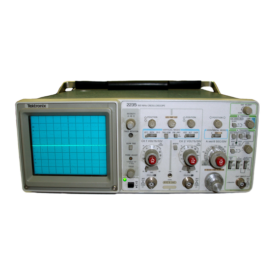
2235 Operators OPERATORS SAFETY SUMMARY The general safety information in this part o f the summary is fo r both operating and servicing personnel. Specific warnings and cautions will be found throughout the manual where they apply and do not appear in this summary. - Page 6 2235 Operators 4 2 0 7 -0 1 The 2235 Oscilloscope.
-
Page 7: Introduction
Section 1 —2235 Operators GENERAL INFORMATION INTRODUCTION The T E K T R O N IX 2235 Oscilloscope is a rugged, light The instrument is shipped with the following standard weight, dual-channel, 100-MHz instrument that features a accessories: bright, sharply defined trace on an 80- by 100-mm cathode-... - Page 8 General Information—2235 Operators Table 1-1 (cont) Performance Requirements Characteristics V E R T IC A L D EFLEC TIO N SYSTEM (cont) Step Response Rise Time 0°C to +35° C 3.5 ns or less. 5 mV per Division to 5 V per Division 3.9 ns or less.
- Page 9 General Information—2235 Operators Table 1-1 (cont) Performance Requirements Characteristics V E R T IC A L D EFLEC TIO N SYSTEM (cont) See Figure 1-1 for derating curve. Maximum Safe Input Voltage 400 V (dc + peak ac) or 800 V ac p-p to 10 kHz or less.
- Page 10 General Information—2235 Operators Table 1-1 (cont) Performance Requirements Characteristics TR IG G E R SYSTEM (cont) L EV E L Control Range A TR IG G ER (NORM) IN T Can be set to any point of the trace that can be displayed.
- Page 11 General Information—2235 Operators Table 1-1 (cont) Performance Requirements Characteristics H O R IZ O N T A L D E F L E C T IO N SYSTEM (cont) Variable Control Range Continuously variable between calibrated settings. Extends the A and B sweep speeds by at least a factor of 2.5.
- Page 12 General Information—2235 Operators Table 1-1 (cont) Characteristics Performance Requirements Z-A XIS IN PUT (cont) Input Resistance 10 k ft ±10%. POWER SOURCE Line Voltage Ranges 90 V to 250 V. Line Frequency 48 Hz to 440 Hz. Maximum Power Consumption 40 W (70 V A ).
- Page 13 General Information—2235 Operators Table 1-2 Environmental Characteristics Description Characteristics NOTE The instrument meets all the following M IL-T-28800C requirements for Type II I, Class 5 equipment. Temperature Operating 0°C to + 5 0 °C (+ 3 2 °F to +122°F).
- Page 14 General Information—2235 Operators Table 1-3 Physical Characteristics Description Characteristics Weight With Power Cord With Cover, Probes, and Pouch 6.2 kg (13.7 1b). Without Cover, Probes, and Pouch 5.2 kg (11.5 lb). Domestic Shipping Weight 7.3 kg (16.0 lb). Height 137 mm (5.4 in).
-
Page 15: Physical Dimensions Of The 2235 Oscilloscope
General Information— 2235 Operators Figure 1-2. Physical dimensions of the 2235 Oscilloscope. ADDJUL 1984... -
Page 16: Calibration
REPACKAGING FOR SHIPMENT Surround the instrument with polyethylene sheeting to If the instrument is to be shipped to a Tektronix Service protect its finish. Obtain a carton of corrugated cardboard Center for service or repair, attach a tag showing; owner... -
Page 17: Section 2 Preparation For Use
Refer to the “Operators Safety Summary” at the front of this manual for power source, grounding, and other safety considerations pertaining to the use of the 2235. Before connecting the instrument to a power source, carefully read C A U T IO N... -
Page 18: Line Fuse
Section 2— 2235 Operators LINE FUSE Line Reference Plug Usage Voltage Standards Configuration North ANSI C73.11 American The instrument fuse holder is located on the rear panel 120V NEMA 5-15-P 1 2 0 V / IEC 83 (see Figure 2-2) and contains the line fuse. The following... -
Page 19: Controls, Connectors, And Indicators
Preparation for Use—2235 Operators CONTROLS, CONNECTORS, AND INDICATORS ( T ) FOCUS Control—Adjusts optimum display The following descriptions are intended to familiarize definition. the operator with the location, operation, and function of the instrument's controls, connectors, and indicators. © PROBE A DJUST Connector—Provides an approxi... -
Page 20: Vertical
Preparation for Use—2235 Operators VERTICAL X connector provides horizontal deflection, and the signal connected to the CH 2 OR Y connector pro vides vertical deflection. Refer to Figure 2-4 for location of items 9 through 17. ( ? ) CH 1 V O L T S /D IV and CH 2 V O L T S /D IV Switches-... -
Page 21: Horizontal
Preparation for Use— 2235 Operators S ER IA L and Mod Slots—The SER IA LsIot is imprinted and Channel 2 input signals at sweep speeds from with the instrument's serial number. The Mod slot 0.5 ms per division to 0.5 s per division. -
Page 22: Trigger
Preparation for Use— 2235 Operators TRIGGER © A and B S E C /D IV Variable Control—Provides contin uously variable, uncalibrated A Sweep speeds to at least 2.5 times the calibrated setting. It extends the Refer to Figure 2-6 for locations of items 25 through 34. - Page 23 Preparation for Use— 2235 Operators N O R M —Sweep is initiated when an adequate (30 ) A & B IN T Switch—Selects the source of the internal trigger signal is applied. In the absence of a trigger triggering signal when the A SOURCE switch is set signal, no baseline trace will be present.
-
Page 24: Rear Panel
Preparation for Use— 2235 Operators REAR PANEL Refer to Figure 2-7 for location of item 35. (3 5 ) E X T Z -A X IS Connector —Provides a means of con necting external signals to the Z-axis amplifier to intensity modulate the crt display. -
Page 25: In F O R M A T Io N
The most reliable signal measurements are made when The graticule is internally marked on the faceplate of the 2235 and the unit under test are connected by a the crt to enable accurate measurements without parallax common reference (ground lead), in addition to the signal error (see Figure 3-1). -
Page 26: Operator's Adjustments
Operating Considerations—2235 Operators capacitor to charge to the average dc-voltage level of the 2. Insert the probe tip into the oscilloscope GND connector. signal applied the probe. Thus, any large voltage transients that may accidentally be generated will not be applied to the amplifier input when the input coupling switch is moved from GND to AC. -
Page 27: Probe Compensation
Operating Considerations—2235 Operators Set the A SEC/DIV switch to display several cycles of the PROBE ADJUST signal. Use the Channel 1 POSITION control to vertically center the display. Check the waveform presentation fo r overshoot and ro llo ff (see Figure 3-2). If necessary, adjust the probe com... -
Page 29: In S Tr U M E N T
The procedures in this part are designed to assist the user procedure. in quickly becoming familiar with the 2235. They provide information which demonstrates the use of all the controls, 1. Preset the instrument front-panel controls as follows: connectors, and indicators and will enable the user to efficiently operate the instrument. -
Page 30: Displaying A Signal
Operating Procedures—2235 Operators 3. Adjust the A IN T E N S IT Y control for desired display Adjust the Channel 1 POSITION control to center brightness. the display vertically on the crt screen. 4. Adjust Vertical Horizontal POSITION Adjust the A T R IG G E R LEV E L control, if necessary, controls to center the trace on the screen. - Page 31 Operating Procedures—2235 Operators Channel 1 and the Horizontal POSITION controls to center 12. Select BOTH and A D D V E R T IC A L MODE and the trace both vertically and horizontally. Release the observe that the resulting display is 4 divisions in amplitude.
- Page 32 Operating Procedures—2235 Operators 25. Press in and hold the T R IG V IE W push button. 11. Rotate the S E C /D IV Variable control out of the Observe the Channel 1 trigger signal that is present in the CAL detent to its maximum counterclockwise position.
- Page 33 Operating Procedures—2235 Operators 11. Readjust the A TR IG G E R L EV E L control for a Using the Delayed-Sweep Controls stable display. 1. Set the B S E C /D IV switch to 50 ps. 12. Remove the square-wave signal from the CH 1 input Select A L T H O R IZ O N T A L MODE.
- Page 34 Operating Procedures— 2235 Operators 3. Rotate the B D E L A Y T IM E POSITION control Using the Z-Axis Input throughout its range. Observe that the intensified zone of 1. Disconnect the dual-input coupler from the CH 2...
-
Page 35: Basic Applications
(see Figure 4-2, Point A). NONDELAYED MEASUREMENTS After becoming familiar with the capabilities of the 2235 Oscilloscope, the operator can then adopt a con venient method for making a particular measurement. The following information describes the recommended pro... -
Page 36: Instantaneous Dc Voltage
Operating Procedures—2235 Operators 7. Horizontally position the display so that one of the If the waveform moves below the centerline of the crt, positive peaks coincides with the center vertical graticule the voltage is negative. line (see Figure 4-2, Point B). -
Page 37: Algebraic Addition
Operating Procedures—2235 Operators CH 2 V E R T IC A L MODE. This ensures the greatest dynamic range for ADD mode operation. d. To attain similar response from each channel, set both the Channel 1 and Channel 2 AC-GND-DC switches to the same position. -
Page 38: Time Duration
Operating Procedures— 2235 Operators 7 7 ^ POSITIVE LEVE L (B) C H A N N E L 2 DISPLAY (A) C H A N N E L 1 SIG NAL W ITH 3 D IV IS IO N S OF W ITH 3 D IV IS IO N S OF N E G A T IV E OFFSET. -
Page 39: Frequency
Operating Procedures—2235 Operators H O R IZ O N T A L _________ DISTANCE 4 2 0 7 -1 6 Figure 4-7. Rise time. Figure 4-6. Time duration. Preset instrument controls and obtain a baseline EXAM PLE: The distance between the time-measurement points is 8.3 divisions (see Figure 4-6), and the A SEC/... -
Page 40: Time Difference Between Two Time-Related Pulses
In a similar manner to “Time Difference," phase com to 180° phase difference; if so, note this for use later in parison between two signals of the same frequency can be the final calculation). made using the dual-trace feature of the 2235. This method 4-12... -
Page 41: Phase Difference
Operating Procedures—2235 Operators of phase difference measurement can be used up to the frequency limit of the vertical system. To make a phase C H A N N E L 1 C H A N N E L 2 comparison, use the following procedure: Preset instrument controls and obtain a baseline trace, then set the A TR IG G ER SOURCE switch to CH 1. -
Page 42: High-Resolution Phase Difference
(e.g., on assembly line test) may be easily (divisions) and accurately measured with the 2235. To accomplish this, a reference signal of known time duration is first set to an exact number of horizontal divisions by adjusting 5. -
Page 43: T V Line Signal
1.37 8 div x 0.2 ms/div T V Field Signal Factor The television feature of the 2235 can also be used to display T V Field signals. Continuing, for the unknown signal the A S EC /D IV switch setting is 50 /is, and one complete cycle spans 7 1. -
Page 44: Delayed-Sweep Magnification
DELAYED-SWEEP MAGNIFICATION 4. Set the A S EC /D IV switch to a sweep speed which The delayed-sweep feature of the 2235 can be used to displays at least one complete waveform cycle. provide higher apparent magnification than is provided by the X10 Magnifier switch. -
Page 45: Pulse Jitter
Operating Procedures—2235 Operators 6. Adjust the B D E L A Y T IM E POSITION control to Pulse Jitter Time Measurement position the start of the intensified zone to the portion of To measure pulse jitter time: the display to be magnified (see Figure 4-11). -
Page 46: Delayed-Sweep Time Measurements
DELAYED-SWEEP TIME MEASUREMENTS Operating the 2235 Oscilloscope with H O R IZ O N T A L MODE set to either A L T or B will permit time measure ments to be made with a greater degree of accuracy than attained with H O R IZ O N T A L MODE set to A. -
Page 47: Rise Time
Operating Procedures—2235 Operators The 10% point on the waveform intersects the center vertical graticule line. Figure 4-14. B D E L A Y T IM E PO SITIO N control settings. Rise Time The 90% point on the waveform intersects the center vertical The measurement method for rise time is the same as graticule line. -
Page 48: Rise Tim E
Operating Procedures— 2235 Operators EXAM PLE: With the A S EC /D IV switch set to 1 /rs, trace) to the same vertical reference point as used in preced the first B D E L A Y T IM E POSITION dial setting (Point ing step 7 (see Figure 4-16, Point B). - Page 49 Description Part Number sories can be obtained either by consulting the current Probes, 10X, 1.5-m w/accessories P6122 Tektronix Product Catalog or by contacting your Tektronix Field Office or representative. 1 Operators Manual 070-4207-00 Option 02 OPTIONAL ACCESSORIES...
- Page 51 2 2 3 5 O p erato rs Ibktronix COMMITTED TO EXCELLENCE C o p y r ig h t 1 9 8 2 , T e k tr o n ix , Inc. L im ite d lic e n s e : T e k tr o n ix , In c . g r a n ts p e r m is s io n 4 2 0 7 - 2 7 A ll r ig h t s re s e rv e d .
- Page 53 MANUAL CHANGE INFORMATION At Tektronix, we continually strive to keep up with latest electronic developments by adding circuit and component improvements to our instruments as soon as they are developed and tested. Sometimes, due to printing and shipping requirements, we can’t get these changes immediately into printed manuals.
- Page 55 D ate: 5-26-88 Change Reference:_ M 66862 commttted to excellence Product: - 2235 OPERATORS________________________________ Manual Part No.: 070-4207-00 DESCRIPTION Product Group 46 The Standard Test Probes for your instrument have been replaced with the P6109 Test Probes. Please note this change in the Standard Accessories List in this manual.
- Page 57 WIND POWER CORD TIGHT, THEN POSITION MALE RECEPTICAL IN RECESSED AREA OF REAR PANEL 2200 SERIES POWER CORD WRAP...
- Page 59 FIG - 5 POUCH MOUNTING - (2200 INST) POUCH IS MOUNTED ON TOP, SECURED BY THE TWO END PANELS POUCH CAN BE MOUNTED BY ARCHING THE POUCH & SLIDING THE TWO ENDS UNDER THE REAR & FRONT PANELS. (SEE FIG - 1) WHEN POUCH IS SECURED PROPERLY THE (4) SLOTS IN THE METAL POUCH PLATE WILL MATE WITH THE (H) KEYS INSIDE THE FRONT &...
Need help?
Do you have a question about the 2235 and is the answer not in the manual?
Questions and answers