Metrix MX2033 Installation Manual
Digital proximity system
Hide thumbs
Also See for MX2033:
- Operation and maintenance manual (42 pages) ,
- Installation manual (15 pages)
Table of Contents
Advertisement
Quick Links
Digital Proximity System
Installation Manual
Doc# 100545 • REV C (May 2016)
1180
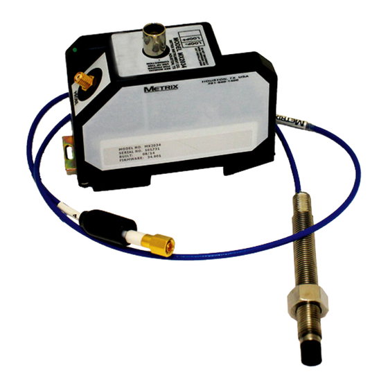
The DPS (Digital Proximity System) family
consists of two devices, the MX2033 and
MX2034. The MX2033 is a conventional
3-wire driver while the MX2034 is a two-
wire current loop transmitter. Users can con-
figure either unit to measure peak-to-peak
vibration, gap distance, or rotational speed.
These products are used in conjunction with
a proximity probe and extension cable to
measure the vibration levels, gap distances,
or rotational speed of machinery shafts.
Users can also configure the units via a USB
cable and configuration software.
Advertisement
Table of Contents

Related Manuals for Metrix MX2033


Summary of Contents for Metrix MX2033
- Page 1 Digital Proximity System Installation Manual 1180 The DPS (Digital Proximity System) family consists of two devices, the MX2033 and MX2034. The MX2033 is a conventional 3-wire driver while the MX2034 is a two- wire current loop transmitter. Users can con- figure either unit to measure peak-to-peak vibration, gap distance, or rotational speed.
-
Page 2: Safety Terms And Symbols
SAFETY TERMS AND SYMBOLS Terms that appear in this manual requiring special attention include: • WARNING: Warning statements identify conditions or practices that could result in injury or loss of life. • CAUTION: Caution statements identify conditions or practices that could result in dam- age to the product, loss or corruption of data, or damage to the environment or other property. -
Page 3: Installation
INSTALLATION Probe Installation Mount the probe in a simple bracket, such as the Metrix Model 7646, in a tapped hole in the bearing cap or by means of a Metrix Model 5499 Probe Housing. The latter arrangement provides an easy means to adjust the probe air gap, especially where the target is some distance from the outside surface of the machine. - Page 4 DC output voltage at the BNC connector on the MX2034 or the terminal block connection on the MX2032 / MX2033 with an isolated meter. Adjust the probe gap to obtain -10 VDC, which corresponds to a gap of approximately 0.050” (1.25 mm). The preferred static gap range is 0.035”...
- Page 5 The probe can be mounted in a simple bracket, such as the Metrix Model 7646, in a tapped hole in the bearing cap or by means of a Metrix Model 5497PM or 5499 Probe Housing. The latter arrangement provides an easy way to adjust the probe air gap, especially where the target is some distance from the outside surface of the machine.
- Page 6 Connect the probe to the transmitter using the proper extension cable such that the com- bined system length of probe + cable matches the transmitter configuration (refer to Metrix datasheet 1028003, ordering option B). Do not change the length of the extension cable from the system, as such action will adversely affect the calibration and linearity.
- Page 7 Route the extension cable using the following guidelines: • Check that the Driver/Transmitter, extension cable, and probe belong to the same system (e.g. Metrix 10000 Series or Metrix 3300 series) and that the total system length is cor- rect (5m or 9m).
- Page 8 MX2033 Field Wiring Installation The driver circuit is insulated from ground by its plastic housing. If grounding of the driver is required, a jumper wire can be used to connect the COM terminal to one of the mount- ing screws. Proper attention must be given to other connections in the circuit to prevent unwanted ground loops which can cause improper operation.
- Page 9 Figure 10: MX2034 wiring with multiple receivers Connect the field wiring (16 to 22AWG) in accordance with the appropriate diagrams. For the MX2034, the minimum power supply voltage is 17 V plus 1 volt for each 50 Ω of loop resistance.
-
Page 10: Hazardous Area Installations
HAZARDOUS AREA INSTALLATIONS MX2034 (DPS) General Requirements Connect the field wiring in accordance with Metrix drawing 100508 for ATEX installations and 100506 for North American installations. Baseefa 05ATEX0195X Exia; Intrinsically Safe II 1G Ex ia IIC T4 Class I, Div. 1, Groups A, B, C,D (-40°C <... - Page 11 Intrinsically Safe Installation in Hazardous Environments The driver requires a minimum of 17 VDC for proper operation. The voltage drop across the specified zener barriers on the installation drawings with a 20 mA loop current is 8.1 VDC. The minimum loop power supply voltage required is 25.1 VDC plus 1 volt for each 50 Ω of loop resistance.
- Page 12 (-40°C < Tamb < 85°C) Temp Code T4 (–40°C ≤ Ta ≤ +85°C) Connect the field wiring in accordance with Metrix drawing 100509 for ATEX installations and 100506 for UL/CSA installations. The driver requires a minimum of 17 VDC for proper opera- tion.
- Page 13 Example: Single wire resistance = 5 Ω Resistance of receiver = 50 Ω Total loop resistance = 55 Ω Minimum supply voltage = 55 Ω (1 VDC/50 Ω) + 25.1 VDC = 26.2 VDC SPECIAL CONDITIONS OF SAFE USE: The apparatus must be mounted within a separate enclosure capable of withstanding a 7 joule impact and providing a minimum ingress protection of IP54.
- Page 14 Baseefa 06ATEX0113X Ex nA IIC T4 (–40°C ≤ Ta ≤ +85°C) SPECIAL CONDITIONS OF SAFE USE: Connect the field wiring in accordance with Metrix drawing 1113106. When the apparatus is being used in accordance with the type of protection: Ex nA IIC T4 (–40°C ≤...
-
Page 15: Environmental Information
(commonly known as WEEE) should never be disposed of in the public waste stream. The “Crossed-Out Waste Bin” label affixed to this product is a reminder to dispose of this product in accordance with local WEEE regulations. If you have questions about the disposal process, please contact Metrix Customer Services. Doc# 100545 •... - Page 16 All trademarks, service marks, and/or registered trademarks used in this document belong to Metrix Instrument Company, L.P. except as noted below: Teflon® is a mark of DuPont in the United States and other countries. © 2014, Metrix Instrument Company, L.P. All rights reserved.
Need help?
Do you have a question about the MX2033 and is the answer not in the manual?
Questions and answers