Table of Contents
Advertisement
Advertisement
Table of Contents

Subscribe to Our Youtube Channel
Related Manuals for Stiegelmeyer Seta pro


Summary of Contents for Stiegelmeyer Seta pro
- Page 1 Seta pro Instruction Manual Model variant junior 2020-11-12 | Version 00 | 288675...
- Page 2 Seta pro hospital bed (junior variant) [1] Top handrail of the headboard (re- [2] Laminate panel (removable at movable at head end only) head end only) [3] Release button for top handrail on [4] Full-length safety side (full-length, the headboard (head end only)
-
Page 3: Table Of Contents
Contents Address, market information................. 1 Foreword........................2 Target groups, qualifications and duties.............. 3 Operator........................... 3 Responsibilities of the operator.................... 3 Users (medical personnel)..................... 4 Users (technical personnel)....................4 Qualification of users......................4 Duties of users........................4 Patient............................5 Conventions of this instruction manual............... 6 Safety instructions........................ - Page 4 6.5.3 Chassis........................20 6.5.4 Electric drive system....................21 6.5.5 Control units......................21 6.5.6 Safety sides.......................34 6.5.7 Linen holder......................34 6.5.8 Mains cable holder....................36 6.5.9 Adapter sleeves for patient lifting pole/infusion stand (optional)....... 36 6.5.10 Universal holders (optional)..................37 6.5.11 Attachment points for posey belts (optional).............
- Page 5 Restoring factory settings....................61 8.8.1 On the LCD handset....................62 8.8.2 On the control box.....................64 Decommissioning......................... 64 Use/routine......................65 Move and immobilise the bed....................65 9.1.1 Safety information on moving, braking and immobilising the bed......66 9.1.2 Moving the bed......................67 9.1.3 Immobilising the bed....................
- Page 6 9.9.2 Trendelenburg Position on the Control Box.............. 81 9.9.3 Reverse-Trendelenburg Position on the Control Box..........81 9.10 Switching under bed light on/off (optional equipment).............82 9.10.1 On the LCD handset....................82 9.10.2 On the control box (optional)..................83 9.11 “Easy Care” function......................83 9.11.1 Activation on LCD handset..................84 9.12...
- Page 7 Cleaning and disinfection.................. 108 12.1 Safety information on cleaning and disinfection............. 108 12.1.1 Before starting cleaning..................108 12.1.2 After cleaning......................108 12.2 Manual cleaning........................109 Maintenance......................111 13.1 Service address........................111 13.2 Safety instructions on maintenance.................. 111 13.2.1 Legal principles....................... 112 13.3 Recommended special varnishes..................112 13.4...
- Page 8 16.3 Disposal of components.....................141 16.3.1 Electrical components..................... 141 16.3.2 Batteries........................142 Appendix......................144 17.1 Available accessories......................144 17.2 Information on electromagnetic compatibility (EMC)............145 17.2.1 EMC information tables...................146 17.3 Inspection report......................... 149 17.4 Inspection by the user......................154 17.5 Translation of EC Declaration of Conformity..............156...
-
Page 10: Address, Market Information
Address, market information Manufacturer Stiegelmeyer GmbH & Co. KG Ackerstraße 42, D-32051 Herford, Germany Phone: +49 (0) 5221 185 - 0 Fax: +49 (0) 5221 185 - 252 Email:info@stiegelmeyer.com Internet:www.stiegelmeyer.com To order replacement parts in Germany and for any servicing requirements or other ques- tions, please contact our service centre: Stiegelmeyer GmbH &... -
Page 11: Foreword
Even after you have purchased a bed, Stiegelmeyer is still on hand to help at any time. Our Assist business division can provide you with customised solutions in all matters relating to inspection and maintenance, repair and process optimisation. -
Page 12: Target Groups, Qualifications And Duties
Target groups, qualifications and duties Operator An operator (e.g. clinic, hospital, hospital administration) is every natural and legal person with property rights to the product. The operator is responsible for the safe operation of this medical product. Responsibilities of the operator Operators of medical beds in Europe are obliged, in accordance with the new Medical Device Regulation (EU) 2017/745 (MDR) and any existing additional relevant national laws/regula- tions, e.g. -
Page 13: Users (Medical Personnel)
Target groups, qualifications and duties Users (medical personnel) Users (e.g. medical specialists, doctors, nursing staff, carers and attendants, ...) are persons who, based on their training, experience or briefing, are qualified to operate the bed on their own authority or to carry out work on it, or have been instructed in how to handle this bed. Furthermore, they can recognise and avoid potential dangers and assess the clinical condi- tion of the patient. -
Page 14: Patient
Target groups, qualifications and duties Please also follow the corresponding instructions in the instruction manual for accessories at- tached to the bed. Pay special attention here to the safe routing of all loose connector cables, tubing, etc. Ensure that no obstacles such as bedside cabinets, supply rails or chairs could impede ad- justments to the bed. -
Page 15: Conventions Of This Instruction Manual
Conventions of this instruction manual Safety instructions In this instruction manual, safety information is displayed in the following way: WARNING WARNING • WARNING indicates a potentially hazardous situation that, if not avoided, could result in death or serious injury. CAUTION CAUTION •... -
Page 16: Icon Information
Conventions of this instruction manual Icon information General information and cross-references will be displayed in the following way: General information, tips and helpful courses of action. Cross-reference or active link: Indicates the chapter name and page number of the instruction manual where you will find what you are look- »... -
Page 17: Safety Instructions
Safety instructions Safety information for operating the bed WARNING Danger when used for unsuitable patient groups This hospital bed is only suitable for patients (children and small adults) with a height of 125 cm to 155 cm. • When used for smaller patients there is a potential increased risk of entrapment/strangu- lation and falls within and over raised safety sides and between raised mattress base parts. -
Page 18: Operating Time Of Electric Drives
Safety instructions • Route the mains cable in such a way that it cannot be pulled, driven over or damaged by moving parts, or in any other way, when the bed is operated. Before moving the bed, al- ways make sure that you have unplugged it from the mains supply. •... - Page 19 Safety instructions WARNING Risk of injury and strangulation for children Handsets and their cables must be stored safely out of reach of children when not in use if children are left unsupervised in the same room as the bed. • Stow all existing hand sets with cables in storage compartments located in the centre un- der one or both long sides of the mattress base.
-
Page 20: Handset (Optional: Handset/Lcd Handset)
Safety instructions 5.1.4 Handset (optional: handset/LCD handset) ATTENTION Material damage Failure to heed this warning may result in collisions between the handset and other items or equipment. This can lead to defects or accidentally trigger unlocked adjustment functions. • When not in use, stow the handset in the holders on the bed in such a way that it cannot inadvertently fall off, and ensure that the keypad on the outside of the bed is protected from unintended use. -
Page 21: Bed Adjustment
Safety instructions WARNING Risk of injury Failure to heed this warning may result in injury. Lock the operating functions for the patient on the handset if • The patient is unable to operate the bed safely, • The patient is unable to free himself or herself from potentially dangerous situations, •... -
Page 22: Special Hazards
Safety instructions • When making any adjustments, always ensure that no limbs belonging to patients, users, other persons, and especially playing children, could become trapped underneath the rests or the mattress base. • When making any adjustments,make sure that devices in the immediate vicinity or attach- ed to the bed cannot become an entrapment or tipping hazard ATTENTION Material damage... -
Page 23: Electromagnetic Interference
Safety instructions • Inform patients that smoking is not allowed in bed. • Only use additional equipment (e.g. electric blankets) and other electrical devices (e.g. lamps, radios) that are in perfect working order! • Ensure that this equipment is used only for the purpose intended. •... -
Page 24: Safety Information For Attachments, Accessories And Additional Equipment
• Efficient and safe operation combined with maximum protection of patients can only be guaranteed if original Stiegelmeyer accessories are used that are designed for the rele- vant model of bed! •... - Page 25 Safety instructions Image1: Connection pin and potential equalisation symbol In addition, observe the information given in: » • Chapter Electromagnetic interference and chapter Safety information concerning » the place of use • All the information given in the instruction manuals of the additional devices as well as the requirements stipulated in the relevant standard EN 60601-1.
-
Page 26: Safety Information For Disposal
When returning BA21-type lithium-ion batteries, use only the transport packaging speci- fied for this purpose in accordance with UN3480! (For this purpose, re-use the original transport packaging provided by Stiegelmeyer for the replacement batteries supplied) • For returns, the requirements of the European Agreement on the International Carriage of Dangerous Goods by Road (ADR) and the resulting national laws must be observed. - Page 27 • Do not dispose of batteries with domestic waste. • They can be returned to Stiegelmeyer or disposed of at local waste collection points in the same way as car batteries. • Outwardly undamaged, discharged battery sets can also be returned to Stiegelmeyer.
-
Page 28: Product Description
Product description Product Description This bed fulfils all the requirements of the Medical Device REGULATION (EU) 2017/745 (MDR) and is considered a Class I medical device in accordance with the classification rules. Intended use • This bed is designed for positioning and transporting patients, as an aid to diagnosing, monitoring, treating, and alleviating illnesses or compensating for injuries or disabilities. -
Page 29: Side Effects
Product description • This bed is suitable for repeated use. • This bed must not be used in explosive environments caused, for example, by cleaning agents or anaesthetics. • This bed must not be used in combination with high frequency surgical equipment. •... -
Page 30: Electric Drive System
Product description 6.5.4 Electric drive system The electrical drive system for this bed consists of the following components: • One drive each for the backrest and thigh rest, and two drives for the mattress base height. • Central control unit under the mattress base (head end). The control unit there uses a transformer to generate a 24-volt protective low voltage which is non-hazardous for pa- tients and users. - Page 31 Product description 6.5.5.1 Handset (Standard) Motorised adjustments can be activated by the patient or user via the handset. Explain the handset functions to the patient: • The drives operate as long as the buttons are pressed. • Adjustments are possible in both directions. •...
- Page 32 Product description 6.5.5.2 Storage options for handsets The following storage options are available for handsets: • On the safety side bar for use by the patient (on either side of the bed) • Safe storage in lockable storage compartments under the mattress base on both sides of the bed to prevent unauthorised access by unsupervised children;...
- Page 33 Product description Lockable storage compartments Similar to illustration! Opening: Insert/remove handset with cable Caution! • Hold the magnetic key provided [a] against cap [b] Do not pinch the cable in the lid • Remove both parts; open the lid Closing: •...
- Page 34 Product description The adjustment options for medical and technical staff are defined at different control levels that each need to be activated separately. Changing between control levels on the LCD handset is done by holding the magnetic sensor [3] on the LCD handset briefly (for about ½ »...
- Page 35 Product description This chapter contains an overview of the adjustment options on the patient control level. • This level is the default level and the handset automatically reverts to this level 10 sec- onds (“EasyCare” level: 2 minutes) after the last button has been pressed at a different level.
- Page 36 Product description Symbol Explanation Symbol Explanation Auto contour adjustment All adjustment options function locked Control level 2: Medical staff control level This provides an overview of the adjustment options at the control level for medical person- nel (staff control level). •...
- Page 37 Product description Medical staff control level: Toggle switch functions Symbol Explanation Symbol Explanation Resuscitation position ad- Thigh rest locking justment function function Shock position (Trendelen- Sitting position burg position) adjustment locking function function Automatic washing system Foot pedal locking position function (optional) Trendelenburg/reverse-Tren- Switching under...
- Page 38 Product description Image4: Technical staff control level: Toggle switch functions Symbol Explanation Symbol Explanation Function: Restrict maxi- Function: Restore fac- mum mattress base height tory settings Function: Delete maximum Function: Define auto- mattress base height matic washing system position Function: RESET Function: Limit mini- mum mattress base height...
- Page 39 Product description magnetic unlocking key is necessary to access the medical staff and technician control level on the LCD handset. Changing between control levels on the LCD handset is done by hold- ing the magnetic sensor on the LCD handset briefly (for about ½ second) against the mag- »...
- Page 40 Product description Button/display Explanation Unlock button Memory button Sitting position button Emergency CPR button (to return all mattress base sections quickly to a flat position) Normal position button Shock recovery position button (Trendelenburg position) Battery charge indicator A yellow LED indicates the charging status when the bed is plugged into the mains socket: •...
- Page 41 Product description Button/display Explanation Raise thigh rest Lower thigh rest Adjust height: Raise mattress base Adjust height: Lower mattress base Reverse-Trendelenburg position Trendelenburg position Buttons for locking and unlocking each of the functions UP button for each function DOWN button for each function Using the control box Instruction Manual...
- Page 42 Product description WARNING Risk of injury Failure to heed this warning may result in strangulation by control box cables. • Lock the linen holder using the integrated magnetic lock if children are left unsupervised in the same room as the bed: To secure the control box from unauthorised access, see »...
-
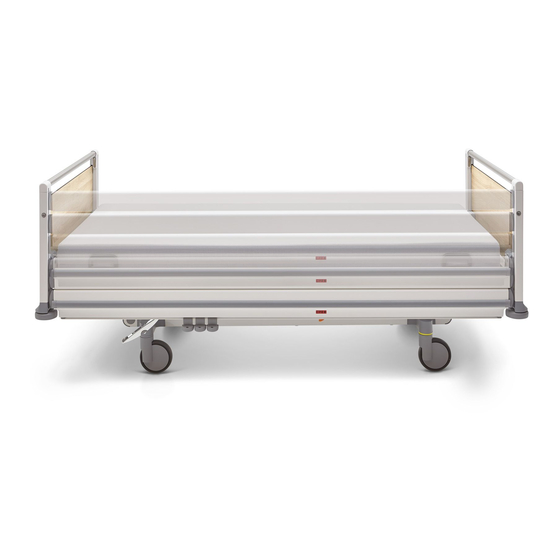
Page 43: Safety Sides
Product description 6.5.6 Safety sides This bed is equipped with full-length safety sides to protect the patient from accidentally fall- ing out of bed. The safety sides are divided into two bars which nursing staff can lower by hand. The lower bars have an integrated rail to which universal holders can be attached. Image6: Full-length safety side 6.5.7... - Page 44 Product description 6.5.7.1 Using the linen holder ATTENTION Material damage Failure to heed the maximum loading capacity of the linen holder (15 kg) will result in mate- rial damage. ⁃ Do not sit/lean on the linen holder! ⁃ Do not lay any hard objects on it. Hard objects can accidentally press the keys of electri- cal control devices, if available, inside the linen holder and lead to malfunctions.
-
Page 45: Mains Cable Holder
Product description Pull the linen holder out from under the mat- A gallery rail is attached to the linen tress base with a slight jerk. holder. If necessary, raise the gallery rail to an upright position. This helps to hold the bedding in place. 6.5.8 Mains cable holder The mains cable holder [1] is attached to the mains cable. -
Page 46: Universal Holders (Optional)
Product description CAUTION Risk of injury Failure to heed this warning may result in injury to children who are playing unsupervised due to sharp edges and burrs on the adapter sleeves for patient lifting poles. • Always use the patient lifting pole inserted and have any sharp edges removed during an- »... -
Page 47: Attachment Points For Posey Belts (Optional)
Product description Image10: Universal holders 6.5.11 Attachment points for posey belts (optional) The plastic mattress base can optionally be fitted with slots for posey belts. The arrows show slots in the plastic mattress base through which restraint system belts can be threaded. WARNING Risk of injury Failure to heed this warning may result in injuries to the patient. -
Page 48: Li-Ion Battery (Optional)
Batteries need to be replaced when operation cycles become very short. For safety reasons, at least one more height adjustment (up + down) should always be possible. Otherwise, the batteries must be replaced. In this case, contact Stiegelmeyer’s service centre. We will re- place rechargeable batteries and dispose of the old batteries correctly. -
Page 49: Lead-Acid Battery (Optional)
Product description Button Explanation Battery fully charged Battery approx. 2/3 charged Battery approx. 1/3 charged - connect bed to power supply as soon as pos- sible Battery empty - connect bed to power supply as soon as possible Bed connected to power supply: Control box indication Indication on the display Explanation... - Page 50 (up + down) should always be possible under normal load. Otherwise, the lead-acid batteries must be replaced. In this case, contact Stiegelmeyer’s service centre. We will replace the rechargeable lead- acid batteries and dispose of the old batteries properly.
-
Page 51: Technical Data
Product description Technical data Please note: All indications of dimensions and weights in this manual are approximate. 6.6.1 Type plate The type plate is at the head end of the mattress base (inner side) and contains the following information: Image12: Type plate( example) Symbol Explanation... -
Page 52: Other Labelling On The Product
Product description Symbol Explanation Symbol Explanation PID bar code The additional PID bar code on the bed includes a number that clearly identifies each particular bed. 6.6.2 Other labelling on the product Symbol Explanation Symbol Explanation Caution! Follow the operat- Safe working load = ing instructions max. -
Page 53: Materials Used
Product description 6.6.3 Materials used The bed is made predominantly of steel sections coated with a polyester powder finish or a zinc or chromium metal finish. Depending on the bed model, the mattress base is made of high-quality, PVC-free plastics, or HPL laminated panels. -
Page 54: Weight
Product description 6.6.5 Weight Description Safe working load 175 kg Empty weight of bed (depending on features) approx. 135 kg Maximum weight of patient* 135 kg to 165 kg* Maximum total weight of bed approx. 310 kg » * : See also Information on loading capacity of bed 6.6.6 Adjustment ranges... -
Page 55: Medical Device Classification
Product description Ambient conditions for Minimum Maximum storage Storage temperature - 10°C + 50°C Relative humidity 20 % 80 % (non-condensing. At alti- tude ≤ 3000 m) Air pressure 700 hPa 1060 hPa Ambient operating condi- Minimum Maximum tions Ambient temperature + 5°C + 40°C Relative humidity... -
Page 56: Electrical Data
Product description 6.6.10 Electrical data Mains cable: (coiled, anti-kink, with strain relief) Type H05 BQ-F 3 x 1 mm 2 (EPR quality) Handset (optional equipment) Type HB 85 OpenBus, with optional backlight Operating voltage DC 24 V Protection category IPX6 LCD handset (optional equipment) Type SHS003, not suitable for automatic washing systems... - Page 57 Product description Control unit Output voltage DC 24 V Output current Max. 10 A (electronic monitoring and cut-out) Settings button Intermittent duty: 2 min ON / 18 min OFF Classification Protection class I, IEC 60601-1-compliant type B device with in- ternal power supply (if fitted with batteries), not for use in explo- sive atmospheres Protection category...
- Page 58 Product description Li-Ion Battery, External (Optional) Type Lithium ion technology: Nickel manganese cobalt oxide (NMC); environmentally-friendly without heavy metals; integrated elec- tronic charger unit with balancer and extended battery monitor- ing; Weight 0.7 kg Capacity 2.25 Ah/ 58.28 Wh Charging time Approx.
- Page 59 Product description Drive M2: (electric) thigh rest motor (depending on model) Type LINAK LA27 Force/installation dimension/lift 4000 N / 272 mm / 70 mm End position cut-out Micro-switch, with analogue coding Input voltage DC 24 V Duty cycle Intermittent duty: 2 min ON / 18 min OFF Protection category IP X6 Drive M4: (electric) backrest motor (depending on model)
-
Page 60: Putting Into Service
Putting into service No electrical measurements are necessary prior to putting this bed into service for the first time, since the bed was tested by the manufacturer for electrical safety and functionality and left our factory in perfect condition. Remove all transport securing devices (from the pedals) and packaging film (from the bed frame). -
Page 61: Safety Information For Electric Hospital Beds
Putting into service • Observe the special safety information on transporting the bed and on moving and immo- bilising the bed; see Safety information on moving, braking and immobilising the » • Before using the bed on parquet flooring, check whether the castors will leave stains on the parquet varnish. -
Page 62: Bed Reprocessing/Bed Adaptation
Bed reprocessing/bed adaptation New occupancy after a change of patient 8.1.1 Information on loading capacity of bed The safe working load specified for a bed is always calculated from the weight of the patient plus the weight of any accessories attached. The permissible weight of the patient depends on the total weight of the accessories attached at the same time (e.g. -
Page 63: Requirements
Bed reprocessing/bed adaptation 8.1.2 Requirements Before putting the bed into service or the bed is occupied by a new patient, the user must check that: • The bed has been cleaned and disinfected • The castor brakes are applied • No obstacles such as bedside cabinets, supply rails or chairs will impede bed adjust- ments •... -
Page 64: Insert/Remove Patient Lifting Pole
Bed reprocessing/bed adaptation • Always lay the mattress [1] on the mattress base between the four lateral mattress retain- er bars [2] . This prevents the mattress from moving outwards at the sides of the bed. • Please also note any other possible position markings on the mattress (such as “Oben/ Top”;... - Page 65 Bed reprocessing/bed adaptation CAUTION Health risks and material damage Failure to heed this warning may result in health risks and damage to property! • The maximum loading capacity at the front end of the patient lifting pole is 45 kg. •...
-
Page 66: Attaching The Grab Handle
Bed reprocessing/bed adaptation Attaching the grab handle CAUTION Risk of injury Failure to heed this warning may result in physical injuries! • Only use the special grab handle with integrated strangulation protection for children (openings smaller than 60mm; prevents children from poking their head through) (see »... -
Page 67: Attaching An Infusion Stand
Bed reprocessing/bed adaptation Attach the grab handle with the strap The integrated anti-slip fitting must be to the patient lifting pole. secured properly between the two limit points of the patient lifting pole. Attaching an infusion stand Only possible if this bed is equipped with the optional adapter sleeve for patient lifting poles/infusion stands. -
Page 68: Using Universal Holders
Bed reprocessing/bed adaptation WARNING Danger of collision and injury Failure to heed this warning may result in physical injury and damage to property! • Adjust (reduce/enlarge) telescopic infusion stands so that they cannot cause injury or damage to property when used on beds. Using universal holders CAUTION Risk of trapping and impact... - Page 69 Bed reprocessing/bed adaptation • If the mattress base height is lowered considerably, note that objects inserted in the proc- ess may become detached from the universal brackets and fall off onto the floor • Ensure that the accessories attached do not collide with the brake pedal area. Slide the universal holders away accordingly.
-
Page 70: Laying The Patient In The Bed
Bed reprocessing/bed adaptation Image13: Urine bottle holder, universal accessory holder Laying the patient in the bed When positioning the patient in bed, always ensure that the patient is correctly aligned with the head end/foot end of the bed. In this way, you achieve maximum lying comfort and adjust the mattress base elements to an optimal ergonomic position for the patient. -
Page 71: On The Lcd Handset
Bed reprocessing/bed adaptation 8.8.1 On the LCD handset Press the UP and DOWN buttons si- Keep both the UP and DOWN buttons multaneously and at the same time pressed for a further 5 seconds while hold the top end of the handset brief- the warning triangle symbol is dis- ly (for approx. - Page 72 Bed reprocessing/bed adaptation Press the UP button to confirm that Press the UP and DOWN buttons si- you wish to select the factory set- multaneously for approximately 5 ting function and to continue the seconds until the pulsating signal procedure. The display changes. tone that is heard stops.
-
Page 73: On The Control Box
Bed reprocessing/bed adaptation 8.8.2 On the control box Press the two marked buttons until the continuous signal tone stops. Decommissioning If the bed is not used for an extended period, please follow the instructions below for taking the bed out of service safely and ensuring ideal conditions for its re-use: »... -
Page 74: Use/Routine
Use/routine Move and immobilise the bed The bed is equipped with four lockable castors which can be centrally operated using a brake pedal at the foot end of the bed. One of the castors at the head end of the bed has a steering lock that can be activated. This makes it easier to move the bed in a straight line. -
Page 75: Safety Information On Moving, Braking And Immobilising The Bed
Use/routine 9.1.1 Safety information on moving, braking and immobilising the bed WARNING Risk of injury Failure to heed this warning may result in life-threatening injuries due to electric shock. Each time before moving the bed, ensure that • The mains cable cannot be stretched, driven over or damaged in any other way, •... -
Page 76: Moving The Bed
Use/routine • As a general rule, always apply the brakes when the bed is not being moved or when a patient is left unattended in the bed. • Make sure that the mattress base has travelled to its lowest position before leaving the patient unattended. -
Page 77: Immobilising The Bed
Use/routine Set the brake pedal to a horizon- tal middle position. All castors are now unlocked. You can now move the bed. 9.1.3 Immobilising the bed Similar to images! The brake pedal is located at the foot end of the bed. Press the pedal down on the side facing the footboard (if colour co- ded, the red side of the pedal). -
Page 78: Locking/Unlocking Electric Adjustment Functions
Use/routine The brake pedal is located at the foot end of the bed. Set the brake pedal to a horizon- tal middle position. Set the castors to the direction in which you wish to move the bed. Lower the brake pedal on the castor. -
Page 79: On The Lcd Handset
Use/routine Lock the operating functions for the patient on the handset if: • If the patient is not able to operate the bed safely or to extricate himself/herself from dan- gerous situations • If the patient could be harmed by unintentional or inadvertent adjustments made by the drives •... -
Page 80: On The Control Box
Use/routine Hold the top end of the LCD handset Use the toggle switch to select the ad- briefly (for about ½ second) against justment function that you wish to lock. the orange magnetic unlocking key On the display, an opened padlock will to gain access to the staff control lev- appear above the symbol for the un- el on the LCD handset. -
Page 81: Setting The Normal Position
Use/routine Keep one of the two unlock buttons pressed. In addition, press the locking button concerned for an unlocked function (green LED on) to lock the adjustment function. The sta- tus can be changed from locked to unlocked and vice versa by alternating between these buttons. -
Page 82: On The Handset
Use/routine 9.4.1 On the handset Press the UP button to set the bed to the auto contour position. Press the DOWN button to set the mattress base to a flat position. 9.4.2 On the LCD handset Select auto contour using the toggle Press the UP button to set the bed to switch. -
Page 83: On The Lcd Handset (Optional)
Use/routine 9.5.2 On the LCD handset (optional) Select the backrest adjustment func- Press the UP button to raise the back- tion using the toggle switch. rest. Press the DOWN button to lower the backrest. Optional: Multi-stage angle display with setting facility for automatic intermediate stop The angle is shown in increments of 15°... -
Page 84: On The Control Box
Use/routine Switching ON/OFF: Switch to the “medical staff control level” • Hold the end of the handset briefly against the magnetic unlocking key. Select with the toggle switch and confirm your selection with the UP button Reprogramming the intermediate stop angle Set the intermediate backrest stop to the desired position Switch to the “technician control level”... -
Page 85: Setting The Bed Height
Use/routine Setting the bed height The mattress base height is continuously adjustable. The adjustment range can be restricted electronically on the handset/LCD handset and the control box (see Special bed adapta- » tions 98). If the mattress base is tilted, it moves automatically into a horizontal position when it reaches the highest or lowest height setting. -
Page 86: On The Control Box
Use/routine 9.6.3 On the control box This function can only be activated when all adjustment functions have been unlocked. To move the mattress base height to a certain height, proceed as follows: To raise the mattress base, press the height ad- justment UP button at the same time as the un- lock button. -
Page 87: On The Control Box
Use/routine Select the thigh rest adjustment func- Press the UP button to raise the thigh tion using the toggle switch. rest. Press the DOWN button to lower the thigh rest to the normal position again. 9.7.3 On the control box Press the thigh rest UP button and the unlock button at the same time to raise the thigh rest. -
Page 88: On The Handset
Use/routine 9.8.1 On the handset The sleep position can only be activated using the handset. Press button [1] to adjust the bed to a sitting position. Press button [2] to adjust the bed to the sleep position. 9.8.2 On the LCD handset Select the sitting position adjustment Press the UP button until the bed is set function using the toggle switch. -
Page 89: On The Control Box
Use/routine 9.8.3 On the control box Press the sitting position button and unlock button at the same time to set the bed to a sitting position. Setting a Trendelenburg or Reverse-Trendelenburg Position 9.9.1 Trendelenburg and reverse-Trendelenburg positions on the LCD handset Hold the top end of the LCD handset Next, select the Trendelenburg position briefly (for approx. -
Page 90: Trendelenburg Position On The Control Box
Use/routine Press the DOWN button until the bed To obtain a reverse-Trendelenburg po- is set to the Trendelenburg position. sition, press the UP button. Once the mattress base has reached The display indicates the angle in in- a horizontal position, an automatic crements of 6°... -
Page 91: Switching Under Bed Light On/Off (Optional Equipment)
Use/routine Press the unlock button and the reverse-Trendelenburg posi- tion button until the full extent or the desired position is reached. 9.9.3.1 Reverting to horizontal bed position Press the unlock button and the Trendelenburg button at the same time. The mattress base automatically moves to the horizontal po- sition, and stops there. -
Page 92: On The Control Box (Optional)
Use/routine the orange magnetic unlocking key on the display and an OFF status will to gain access to the staff control lev- be displayed for the turned off under el on the LCD handset. bed light. Press the UP or DOWN button. The under bed light is now switched on and an ON status is displayed. -
Page 93: Activation On Lcd Handset
Use/routine care tasks have been completed, the system automatically returns to the first level after 2 mi- nutes. Alternatively, this can be switched over manually. Previously set function locks for indi- vidual adjustments are retained. CAUTION Risk of injury Failure to heed this warning may result in injuries to patients due to unintentional activation of bed adjustments that may pose a risk, e.g. - Page 94 Use/routine While the " Easy Care" control level is activated, the "EC" logo also always ap- pears in the top right-hand corner of the display Deactivation • Automatically: 2 minutes after the last key was pressed or • Immediately: by briefly holding the handset sensor [2] against the magnet. The handset reverts to the last active adjustment function in the “Patient”...
-
Page 95: Using Safety Sides
Use/routine Symbol Explanation Symbol Explanation Thigh rest adjustment func- Shock position (Trende- tion lenburg position) adjust- ment function » For detailed descriptions of the individual functions, see Use/routine 9.12 Using safety sides Safety sides provide suitable protection for patients against falling out of bed. They are not intended as a device to prevent the patient from intentionally leaving the bed. - Page 96 Use/routine CAUTION Risk of injury Failure to heed this warning may result in physical injury if thicker special mattresses, such as anti-decubitus mattresses, are used (for prevention or therapy). In this case an effective safety side height of at least 22 cm above the non-occupied mattress must still be guaran- teed.
-
Page 97: Full-Length Safety Sides
Use/routine 9.12.1 Full-Length Safety Sides Please note that the use of full-length safety sides is only possible in conjunction with the Base head and footboard. 9.12.1.1 Raising The following section describes how to raise one of the safety sides. The safety sides on the other side of the bed are raised in exactly the same way. - Page 98 Use/routine CAUTION Risk of entrapment and crushing Failure to heed this warning may result in the patient's limbs being entrapped or crushed while lowering the safety sides! • Before lowering the safety sides, ensure that the patient's limbs are not in the radius of movement of the safety side rails.
-
Page 99: Remove/Insert Headboard Handrail
Use/routine Lower the safety side slowly. Do not let it drop! Repeat this procedure at the other end of the bed. 9.13 Remove/insert headboard handrail The laminate panels in the headboard can be removed if required. This may be necessary if the patient has to do rehabilitation exercises in bed, for example. -
Page 100: Insert
Use/routine Pull the headboard handrail evenly up- Pull the headboard panel upwards. wards. Avoid jamming it. After removing the headboard panel, reinsert the handrail to provide stability. The locking mechanism must audibly engage. The panel can be inserted if necessary for resuscitation purposes. 9.13.2 Insert 1 Proceed in reverse order to the removal process. - Page 101 Use/routine 4 Reinsert the handrail on the headboard. Instruction Manual...
-
Page 102: Special Functions
Special functions 10.1 Setting the shock recovery position The bed moves to the shock position at maximum speed. The backrest and thigh rest move simultaneously to the horizontal base position. WARNING Risk of injury and material damage Failure to heed this warning may result in patients and other people being exposed to dan- ger and property being damaged. -
Page 103: On The Control Box
Special functions Hold the top end of the LCD handset Next, select the shock position adjust- briefly (approx. ½ second) over the ment function using the toggle switch. magnetic unlocking key at the foot end of the bed to gain access to the staff The quickest way to access this func- control level on the LCD handset. -
Page 104: Setting Cpr Position
Special functions 10.1.2.1 Reverting to horizontal bed position Press the unlock button at the same time as the reverse- Trendelenburg UP button. The mattress base automatically moves to the horizontal po- sition at mid-height. 10.2 Setting CPR position The CPR position allows all parts of the mattress base to be lowered quickly. It is also suita- ble for moving the bed to a specific low position for the patient to sleep at night (fall preven- tion). -
Page 105: On The Lcd Handset
Special functions 10.2.1 On the LCD handset Hold the top end of the LCD handset The CPR adjustment function is pre- briefly (for about ½ second) against set. the orange magnetic unlocking key to Press the UP or DOWN button until the gain access to the staff control level bed has reached the desired position. - Page 106 Special functions ⁃ In such cases, carry out this procedure with two persons: One person on each side of the bed. ⁃ Always keep hold of the backrest handle with one hand so as to “control” the adjustment. This function is possible at any time - even in the event of power supply outages or elec- trical drive system failures.
-
Page 107: Special Bed Adaptations
Special bed adaptations 11.1 Attaching posey belts WARNING Risk of injury Failure to heed this warning may result in injury. • Please observe the instruction manual and safety information provided by the manufactur- er of the restraint systems before and while restraining a patient, in order to prevent the risk of serious injuries to the patient! •... -
Page 108: Restricting The Maximum Mattress Base Height
Special bed adaptations 11.2 Restricting the maximum mattress base height A pre-set maximum mattress base height cannot be exceeded in the daily care routine or by the patient. When the bed is raised, it only moves to this position and then stops. A maximum mattress base height can only be defined by service personnel or qualified medical staff who have been trained by the operator to do so. -
Page 109: Deleting The Maximum Mattress Base Height Setting (On The Lcd Handset)
Special bed adaptations The OK ! shown on the display con- Select the maximum mattress base firms the change to the technician height function by pressing the toggle control level. Let go of the UP and switch. DOWN buttons. Press the UP button twice. After After pressing the button for the sec- pressing the button for the first time, ond time, the OK ! displayed indicates... -
Page 110: Setting The Minimum Mattress Base Height (On The Control Box)
Special bed adaptations bol will appear and the status mes- sage X will be displayed for the de- leted function. 11.2.3 Setting the minimum mattress base height (on the control box) The mattress base must be horizontal before a restriction can be defined. Set the mattress base to the desired maximum height. -
Page 111: Restricting Minimum Mattress Base Height
Special bed adaptations 11.3 Restricting minimum mattress base height A pre-set minimum mattress base height cannot be exceeded in the daily care routine or by the patient. When the bed is lowered, it only moves to this position and then stops. A mini- mum mattress base height must only be defined by technical staff or qualified medical staff who have been trained by the operator to do so. -
Page 112: Deleting The Minimum Mattress Base Height Setting (On The Lcd Handset)
Special bed adaptations The OK ! shown on the display con- Select the minimum mattress height firms the change to the technician function by pressing the toggle switch. control level. Let go of the UP and DOWN buttons. Press the UP button twice. After After pressing the button for the sec- pressing the button for the first time, ond time, the OK ! displayed indicates... -
Page 113: Setting The Minimum Mattress Base Height (On The Control Box)
Special bed adaptations 11.3.3 Setting the minimum mattress base height (on the control box) The mattress base must be horizontal before a restriction can be defined. Set the mattress base to the desired minimum height. To do so and lower the mattress base, simultaneously press the un- lock button and the button to lower the mattress base. -
Page 114: On The Lcd Handset
Special bed adaptations Defining an intermediate stopping position must only be done by technical staff or through qualified medical staff who have been trained by the operator to do so. 11.4.1 On the LCD handset Set the backrest to the position that you wish to define as the intermediate stopping position. Press the UP and DOWN buttons si- Keep both the UP and DOWN buttons multaneously and at the same time... -
Page 115: Adjusting The Sitting Position And The Normal Position
Special bed adaptations Press the UP button. A display of OK ! and a beep acknowl- edge that an intermediate stopping po- sition has been successfully set. The symbol for the intermediate stopping position is then displayed again. 11.5 Adjusting the sitting position and the normal position Only possible when equipped with a control box in the linen holder. - Page 116 Special bed adaptations Press the “Save” button three times ... then immediately afterwards only in a row, ... press the desired position button. As soon as the new position has been saved, a short signal tone sounds to confirm the change.
-
Page 117: Cleaning And Disinfection
Cleaning and disinfection 12.1 Safety information on cleaning and disinfection Failure to follow this safety advice could result in considerable damage to the bed and the electrical components and lead to subsequent malfunctions! 12.1.1 Before starting cleaning ⁃ Ensure that all plugs for the drive system are connected as prescribed. ⁃... -
Page 118: Manual Cleaning
For further informa- tion, consult STIEGELMEYER or a specialist dealer of your choice. • Disinfectants based on compounds which could potentially release chlorine may be corro- sive for metals, synthetics, rubbers and other materials over longer contact periods or when concentrations are too high. - Page 119 The choice of cleaning agents and disinfectants available on the market may change from time to time. Stiegelmeyer therefore routinely tests the most commonly used materials for compatibility. The most up-to-date list of tested cleaning agents and disinfectants can be ob- tained on request.
-
Page 120: Maintenance
Service address To order replacement parts in Germany and for any customer service requirements or other questions, please contact our service centre: Stiegelmeyer GmbH & Co. KG Ackerstraße 42, D-32051 Herford, Germany Phone: +49 (0) 5221 185 - 777 Fax: +49 (0) 5221 185 - 219 Email: service@stiegelmeyer.com... -
Page 121: Legal Principles
(source: MDR (Medical Device Regulation), Art. 2(65)). 13.3 Recommended special varnishes Colour Description Stiegelmeyer order number Silver Varnish (500g tin) 203803 Accelerator (100g tin) 203805... -
Page 122: Servicing Plan
Maintenance 13.4 Servicing plan Components Action Interval Information All screw connections Check that they are At least once a year Use suitable tools. and/or metal safety firmly positioned; tight- caps en and/or replace if necessary. Connecting bolts on Clean and slightly At least once a year Use resin-free and the removable head-... -
Page 123: Periodic Inspection
A guide to pre- ventive replacement of potentially relevant components can be obtained from the following address: Stiegelmeyer GmbH & Co. KG Ackerstraße 42, 32051 Herford, Germany Phone: +49 (0) 5221 185 - 777 Fax: +49 (0) 5221 185 - 219 Email: service@stiegelmeyer.com... - Page 124 Maintenance CAUTION Risk of injury and material damage Failure to heed this warning may result in injuries and damage to property. • If any safety-relevant damage or malfunction is suspected during testing in accordance with DIN EN 62353 (VDE 0751-1), take the bed out of service at once until it has been repaired or the damaged components have been replaced! A repeat inspection must be carried out in accordance with the test sheet to determine whether the damage or mal- function has been rectified.
-
Page 125: Replacement Of Electrical Components
Replacement of electrical compo- nents 14.1 Safety instructions WARNING Risk of injury Failure to heed this warning may result in injury due to electric shock. • Any work and/or repairs to the electrical equipment may only be carried out by Stiegel- meyer service engineers, the actuator manufacturer or qualified and authorised electri- cians in compliance with all relevant VDE and safety regulations! •... -
Page 126: Replacing The Battery (Lead-Acid/Li-Ion)
Their housings are fully welded and cannot be opened. When the battery is exchanged, the type of battery can be changed without any problem - this enables you to change over to modern lithium ion technology at a later date. Spare parts can be obtained from Stiegelmeyer. Instruction Manual... - Page 127 Replacement of electrical components CAUTION Risk of injury Failure to heed this warning may result in physical injury due to crushing. • For safe and easy installation, move the mattress base and the backrest to the highest position. WARNING Risk of injury and material damage Failure to heed this warning may result in physical injury and material damage.
-
Page 128: Mains Cable Replacement
Replacement of electrical components Note: The battery is attached to the CO61 control unit from below with a snap system. The control unit is also mounted on top of the mounting bracket in the same way. Press the lower clip upwards and push the battery a few centimetres away from the clip until the battery can be removed downwards. -
Page 129: Connect The Earth Conductor
Replacement of electrical components 14.4 Connect the earth conductor The control unit has a mains cable with a protective earth conductor. The earth conductor is connected to the mattress base frame. After replacing the mains cable, this connection must be re-established and an electrical protective earth conductor measurement must be carried out to test its effectiveness. -
Page 130: Replace Handset
Replacement of electrical components 14.5 Replace handset If possible, raise the bed to its highest position to make work easier. Unplug the mains plug from the electrical socket. » Open the handset storage compartment, see Storage options for handsets Unlock the handset cable by tilting the locking tab upwards on the inside of the storage compartment. -
Page 131: Replace The Control Unit
Replacement of electrical components » Programme the control box, see RESET: Acknowledge faults on control box 140. Test the electric adjustments to ensure they work correctly! Replace the control box in its holder and secure the holder again with the two screws on the underside of the linen holder. -
Page 132: Initialising The Control
Replacement of electrical components LED display (mains/rechargeable battery operation) For easier installation, raise the mattress base and the backrest to the highest position. Unplug the mains plug from the electrical socket. Release the terminals of the control from the locking fitting on the bed: To do so, use your fingers to press down on the protruding snap-in catch located on the centre front of the housing near to the power input and slide the control unit off. -
Page 133: On The Lcd Handset
Replacement of electrical components ATTENTION Risk of malfunctions Failure to heed this warning may result in a malfunction! • The initialisation procedure must only be carried out by technical personnel (technician control level on the LCD handset). Depending on the control devices available, an initialisation is possible in different ways: 14.8.1 On the LCD handset Plug the mains cable from the control into the electric socket. - Page 134 Replacement of electrical components Press the toggle left button once to change Select the initialisation function by press- the display to the next image INIT (step 5). ing the UP button. Press the UP button on the LCD handset. Press the UP button until the bed is raised The height adjustment drive symbol will ap- to its full extent.
-
Page 135: On The Control Box
Replacement of electrical components 14.8.2 On the control box Press buttons 1 - 4 one after the other in the order 1+2+3+4 and keep them press- A signal tone will sound. The reset is suc- cessfully completed once the signal tone has stopped. - Page 136 Replacement of electrical components ATTENTION Risk of malfunctions Failure to heed this warning may result in a malfunction. • The LCD handset must only be programmed by technical staff or qualified medical staff who have been trained by the operator to do so. 1 The warning triangle symbol is displayed on 2 Press the UP and DOWN buttons simultane- the LCD handset.
- Page 137 Replacement of electrical components 5 Press the UP button to confirm that you wish 6 Press the UP and DOWN buttons at the to select the RESET function and to continue same time for 5 seconds. the procedure. The display changes. 7 The display changes again to the RESET sym- 8 Unplug the bed from the power socket for bol.
-
Page 138: Troubleshooting
Troubleshooting 15.1 Faults and their rectification Problem Possible causes Rectification Handset/LCD handset/drive Mains cable not plugged in Plug mains cable in; mains system not working power LED must light up (green) on the control unit No power supply to mains Check socket and fuse box socket Plug not inserted properly... - Page 139 Troubleshooting Problem Possible causes Rectification Then leave the bed connected to the mains for a further 10-12 hours until charging is com- plete Constant signal tone sounds Battery capacity depleted Connect bed to the mains sup- during adjustment ply to recharge the battery as soon as possible Operation only possible for a End of battery life reached...
- Page 140 Troubleshooting Problem Possible causes Rectification box. (for detailed fault indica- tem checked. Inform your oper- tion, see Fault messages on ator about any necessary re- pairs » control box 137) Control unit not working: There is a problem with the Troubleshooting Display screen control unit.
-
Page 141: Fault Display On Lcd Handset
Troubleshooting 15.2 Fault display on LCD handset Faults in the adjustment drives and the control units are indicated on the display. Display screen Type of fault Solution General fault indication on the dis- Start the RESET procedure to dis- play. play the exact error image accord- ing to the troubleshooting guide Adjustment drive cannot be activa-... - Page 142 Troubleshooting Display screen Type of fault Solution » LCD handset 134; RESET: Ac- knowledge faults on control » 140) Check all internal plug connec- tions/components; replace defec- tive parts: • O-seal ring present/correct- ly inserted? • Plug fully inserted as far as it will go and secured against loosening with re- taining clips engaged?
-
Page 143: Reset: Acknowledging Faults On Lcd Handset
Acknowledge the fault as described below. • If the control unit automatically locks again within a short space, contact Stiegelmeyer’s service centre to rectify the cause of the fault. Depending on the bed fixtures, the locked function is indicated by: •... -
Page 144: Displaying/Deleting Last Fault On Lcd Handset
Troubleshooting Press the UP and DOWN buttons simultaneous- ly and at the same time hold the top end of the handset against the orange magnetic unlocking key until the warning symbol disappears and the current fault appears (see Fault display »... - Page 145 Troubleshooting 1 Press the UP and DOWN buttons simultane- 2 Keep both the UP and DOWN buttons press- ously and at the same time hold the top end of ed for a further 5 seconds while the warning the LCD handset briefly (for about ½ second) triangle symbol is displayed.
-
Page 146: Fault Messages On Control Box
Troubleshooting 7 Select the CLEAR function by pressing the 8 Press the UP button to confirm that the fault toggle switch. should be deleted. 9 OK ! confirms the deletion. 15.5 Fault messages on control box If your bed is fitted with this equipment, it is easy to obtain a quick overview of the functional status and to perform a RESET (to acknowledge fault messages) if necessary. - Page 147 Troubleshooting Fault indications on control box Signal Error Solution when button pressed Thigh rest motor (socket Replace cable/check or re- 2) limit switch place plug + perform RESET on control unit (→ chapter Mattress base height mo- RESET: Acknowledging faults tor limit switch, head end »...
- Page 148 Troubleshooting Signal Error Solution when button pressed lying on handset, sol- » handset 134; RESET: Ac- id objects on the linen knowledge faults on control holder) » 140) Loose connection/ Check all internal plug con- moisture ingress in an nections/components; replace ®...
-
Page 149: Reset: Acknowledge Faults On Control Box
Troubleshooting 15.6 RESET: Acknowledge faults on control box 15.6.1 On the control box Press buttons 1-4 one after the other in the order 1+2+3+4 and keep them pressed. A signal tone will sound. Unlocking is successfully completed once the signal tone has stopped. -
Page 150: Disposal
Disposal WARNING Risk of infection Failure to heed this warning can result in health risks! • Please ensure as the operator that all components to be disposed of are not infectious or contaminated. 16.1 Disposal of the bed If the bed is to be disposed of, the plastic and metal parts must be separated and disposed of properly in accordance with relevant local and national environmental regulations and legisla- tion of the town or country concerned. -
Page 151: Batteries
The operator of this bed is legally obliged to return the electrical components directly to the manu- facturer and not to dispose of them at municipal waste collection points. STIEGELMEYER and its service and sales partners will take these components back. The return of these components is covered by our General Terms and Conditions. - Page 152 Disposal WARNING Risk of injury and environmental damage Failure to observe the special safety precautions for Li-ion batteries may result in injury and environmental damage. • Outwardly damaged battery sets must not be shipped. • Dispose of these in non-flammable, leakproof and sealed containers at local collection points in accordance with national regulations.
-
Page 153: Appendix
CAUTION Risk of injury Failure to heed this warning may result in injury. • Use only original Stiegelmeyer accessories that match the corresponding bed model. • This ensures safe and reliable operation and maximum patient safety. ATTENTION Material damage Failure to heed the following information when choosing and installing accessories can re- sult in damage to property. -
Page 154: Information On Electromagnetic Compatibility (Emc)
Appendix Up-to-date lists of accessories can be obtained from Stiegelmeyer and their sales partners by indicating the bed model. The following accessories are available for this bed: • Patient lifting pole with special grab handle (integrated strangulation protection for chil- dren prevents children from poking their head through the handle) »... -
Page 155: Emc Information Tables
Appendix 17.2.1 EMC information tables ATTENTION Risk of malfunctions Failure to heed this warning may result in malfunctions of the bed or of surrounding devices. • The bed is intended for use in the electromagnetic environment described below. The op- erator or user of the bed should ensure that it is used in such an environment. - Page 156 Appendix Sheathing Phenomenon EMC basic standard or Immunity test level test method Professional healthcare facilities Magnetic fields with rated pow- IEC 61000-4-8 30 A/m; 50 Hz or 60 Hz er frequencies AC port for supply input Phenomenon EMC basic standard Immunity test level Professional healthcare facilities...
- Page 157 Appendix Ports for signal input/signal output parts Phenomenon EMC basic standard Immunity test level Professional healthcare facilities Electrostatic discharge (ESD) IEC 61000-4-2 +/- 8 kV; contact +/- 2 kV, +/- 4 kV ¸ +/- 8 kV, +/- 15 kV air Electrical fast transients/bursts IEC 61000-4-4 +/- 1 kV;...
-
Page 158: Inspection Report
[ ] Inspection prior to initial op- eration(reference value) [ ] Inspection following repairs/maintenance Equipment type: [X] Hospital [ ] Care bed Protection class: [X] I [ ] II Bed type: Seta pro Inventory number: Location: Serial number: Instruction Manual... - Page 159 Appendix Inspection of Electromedical Devices according to DIN EN 62353 (VDE 0751-1): 2015-10 Manufacturer: Stiegelmeyer User-specific parts:Mattress GmbH & Co. base, headboard and foot- board, safety sides Testing equipment used (type/inventory no.): Medical Devices Regulation classification:Class I I. Visual inspection...
- Page 160 Appendix I. Visual inspection Description of Defect What? How? Patient lifting No damage or deformation pole, adapter sleeves, grab handle with strap Manufacturer's recommendation: Replace grab handle after 5 years Bed frame: Mat- No damage, deformation, no split welded tress base, chas- seams Castors No damage...
- Page 161 Appendix II. Electrical Measurement according to DIN EN 62353 (VDE 0751-1) Plug the bed mains cable in the test socket on the measuring in- strument Connect the measuring instrument probe to the PE connector (mat- tress base, head end). Activate the motors using the handset for the duration of the measurement.
- Page 162 Appendix III. Performance Check: Not ok Description of Defect What? How? Joints and pivots Smooth operation Lower leg rest Engaged, evenly on both sides Test (Rastomat) according to instruction manual Integrated lower Check plastic holders for breakage leg rest extension (plastic holders) Grab handle with Securely fixed when load tested un-...
-
Page 163: Inspection By The User
Appendix Overall inspection result Test approval sticker [ ] Yes [ ] No Next inspection date: applied: Documents that form part of this inspection report: Checked: Date: Name: Signature: Test approval sticker Date: Name: Signature: applied Address/stamp of responsible company: 17.4 Inspection by the user Check... - Page 164 Appendix Check Not ok Description of Defect What? How? Patient lifting No damage or pole, adapter deformation sleeves Grab handle with No damage strap Chassis No damage or deformation Mattress base, No damage, de- covers; plastic formation, sharp- parts edged breakage Performance Check of the Electrical Components (if Installed) Handset/control For performance...
-
Page 165: Translation Of Ec Declaration Of Conformity
Appendix Check Not ok Description of Defect What? How? Inspector’s signature: Inspection result. Date: 17.5 Translation of EC Declaration of Conformity Continued on the next page. Instruction Manual... - Page 166 Appendix Instruction Manual...
- Page 167 Appendix Instruction Manual...
Need help?
Do you have a question about the Seta pro and is the answer not in the manual?
Questions and answers