Table of Contents
Advertisement
Quick Links
Advertisement
Table of Contents

Related Manuals for Stiegelmeyer Evario one


Summary of Contents for Stiegelmeyer Evario one
- Page 1 Evario one Hospital Bed Instruction Manual 2021-09-15 | Version 01 | 294547...
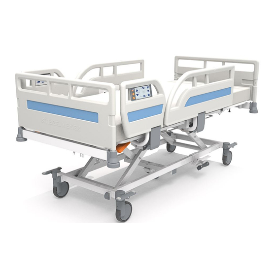
- Page 2 Evario one (split ¾ plastic safety side) Evario one (¾ safety side (swivelling))
- Page 3 [1] Headboard, removable [2] Control panel (inside) for patient (optional equipment) [3] Split ¾ plastic safety side [4] Footboard, removable [5] Linen holder, extensible, with gal- [6] Release buttons for bed extension lery rail (optional equipment) (optional equipment) [7] Brake pedal (to immobilise the [8] Foot pedal (optional equipment) bed) As an optional feature, the bed...
-
Page 5: Table Of Contents
Contents Address, market information................. 1 Foreword........................2 Target groups, qualifications and duties.............. 3 Operator........................... 3 Responsibilities of the operator.................... 3 Users (medical personnel)..................... 4 Users (technical personnel)....................4 Qualification of users......................4 Duties of users........................4 Patient............................5 Conventions of this instruction manual............... 6 Safety information........................6 Icon information........................ - Page 6 6.6.1 Headboard and footboard..................19 6.6.2 Mattress base......................19 6.6.3 Bed chassis.......................19 6.6.4 Electric drive system....................19 6.6.5 Control devices......................20 6.6.6 Safety sides.......................29 6.6.7 Magnetic unlocking key.....................30 6.6.8 Linen holder (optional equipment)................30 6.6.9 Mains cable holder....................32 6.6.10 Adapter sleeves for patient lifting pole/infusion stand (head end)......33 6.6.11 Adapter sleeves for infusion stand (at foot end)............34 6.6.12...
- Page 7 Extending/shortening the mattress base (optional equipment)........53 Integrated lower leg rest extension (optional equipment)..........55 8.3.1 Operation........................56 Bed extension fitting (accessory)..................56 Gap closure for safety side (accessory)................57 8.5.1 Attachment........................ 58 8.5.2 Removal........................60 Inserting the mattress......................61 Inserting/removing patient lifting pole................62 8.7.1 Attaching the grab handle..................
- Page 8 Setting the thigh rest......................84 9.6.1 On the handset......................85 9.6.2 On the control box.....................85 9.6.3 On the control panel (outside)...................85 Setting the lower leg rest......................86 9.7.1 Mechanically......................86 Setting the sitting position....................87 9.8.1 On the handset......................88 9.8.2 On the control box.....................88 9.8.3 On the control panel (inside and outside)..............
- Page 9 11.4.2 On the control panel (outside).................107 Cleaning and disinfection.................. 108 12.1 Safety information on cleaning and disinfection............. 108 12.1.1 Before starting cleaning..................108 12.1.2 After cleaning......................109 12.2 Manual cleaning........................109 Maintenance......................111 13.1 Service address........................111 13.2 Safety instructions for maintenance..................111 13.2.1 Legal principles.......................
- Page 10 Disposal....................... 135 16.1 Disposal of the bed......................135 16.2 Disposal of packaging......................135 16.3 Disposal of components.....................135 16.3.1 Electrical components..................... 135 16.3.2 Batteries........................136 Appendix......................137 17.1 Available accessories......................137 17.2 Information on electromagnetic compatibility (EMC)............138 17.2.1 EMC information tables...................139 17.3 Inspection report.........................
-
Page 12: Address, Market Information
Address, market information Manufacturer Stiegelmeyer GmbH & Co. KG Ackerstraße 42, D-32051 Herford, Germany Phone:+49 (0) 5221 185 - 0 Fax:+49 (0) 5221 185 - 252 Email:info@stiegelmeyer.com Internet:www.stiegelmeyer.com To order replacement parts in Germany, and for any customer service requirements or other questions, please contact our service centre: Stiegelmeyer GmbH &... -
Page 13: Foreword
Even after you have purchased a bed, Stiegelmeyer is still on hand to help at any time. Our Service business division can provide you with customised solutions in all matters relating to inspection and maintenance, repair and process optimisation. -
Page 14: Target Groups, Qualifications And Duties
Target groups, qualifications and duties Operator An operator (e.g. hospital, clinic) is every natural and legal person with property rights to the product. The operator is responsible for the safe operation of this medical product. Responsibilities of the operator Operators of medical beds in Europe are obliged, in accordance with the new Medical Device Regulation (EU) 2017/745 (MDR) and any existing additional relevant national laws/regula- tions, e.g. -
Page 15: Users (Medical Personnel)
Target groups, qualifications and duties Users (medical personnel) Users (e.g. medical specialists, nursing staff, doctors and carers) are persons who, based on their training, experience or briefing, are qualified to operate the bed on their own authority or to carry out work on it, or have been instructed in how to handle this bed. Furthermore, they can recognise and avoid potential dangers and assess the clinical condition of the patient. -
Page 16: Patient
Target groups, qualifications and duties Pay special attention here to the safe routing of all loose connector cables, tubing, etc. Ensure that no obstacles such as bedside cabinets, supply rails or chairs could impede ad- justments to the bed. If other equipment (e.g. compressors for positioning systems, etc.) is attached, ensure that all items of equipment are securely fixed and function properly. -
Page 17: Conventions Of This Instruction Manual
Conventions of this instruction manual Safety information In this instruction manual, safety information is displayed in the following way: WARNING WARNING • WARNING indicates a potentially hazardous situation that, if not avoided, could result in death or serious injury. CAUTION CAUTION •... -
Page 18: Icon Information
Conventions of this instruction manual Icon information General information and cross-references will be displayed in the following way: General information, tips and helpful courses of action. Cross-reference or active link: Indicates the chapter of the instruction manual and the page number where you can find specific information. »... -
Page 19: Safety Instructions
Safety instructions Safety information for operating the bed This hospital bed is not suitable for patients under 146 cm in height or for small children. This hospital bed may only be operated by persons who have received instruction from the operator in its safe operation. -
Page 20: Operating Time Of Electric Drives
Safety instructions • At weekly intervals when the bed is being used, carry out a visual inspection of the mains cable to check for damage (scuffing, exposed wires, kinks, pressure points, etc.). A check should also be performed whenever the cable has been subjected to any mechanical load, e.g. - Page 21 Safety instructions ATTENTION Material damage Failure to heed this warning may result in system faults due to locked adjustment systems. • When routing the handset cable, ensure that it cannot be crushed, stretched or otherwise damaged by any moving parts of the bed. •...
-
Page 22: Bed Adjustment
Safety instructions • children are left unsupervised in the room with the bed. • In these cases, adjustments must only be performed by a person trained by the operator, or in the presence of a trained person! • The following sticker on the linen holder reminds you to lock the handset: 5.1.4 Bed adjustment WARNING... -
Page 23: Special Hazards
Safety instructions • There are no objects lying on the chassis, • People are not sitting on slightly raised sections of the backrest or leg rests. If the load is too high, an electronic overload switch is activated and the drive system is automatically switched off. -
Page 24: Electromagnetic Interference
Efficient and safe operation combined with maximum protection of patients can only be guar- anteed if original Stiegelmeyer accessories are used that are designed for the relevant model of bed! Make sure that by attaching accessories, crush or shearing zones for the patient are not created when the safety sides are adjusted. - Page 25 Safety instructions are involved. The potential equalisation of the bed applies to the mattress base frame. Addi- tional assemblies and accessories (such as headboards and footboards, safety sides, patient lifting poles, infusion stands) are excluded from these requirements. Image1: Connection pin and potential equalisation symbol In addition, observe the information given in: »...
-
Page 26: Use Of Patient Lifts
Failure to heed this warning may result in damage to property and injury due to the use of incorrect accessories and unsuitable spare parts! • Efficient and safe operation combined with maximum protection of patients can only be guaranteed if original Stiegelmeyer accessories are used that are designed for the rele- vant model of bed. Instruction Manual... -
Page 27: Safety Information For Disposal
• Do not dispose of batteries with domestic waste. • They can be returned to Stiegelmeyer or disposed of at local waste collection points in the same way as car batteries. • Outwardly undamaged, discharged battery sets can also be returned to Stiegelmeyer. -
Page 28: Product Description
Product description This bed fulfils all the requirements of the Medical Device REGULATION (EU) 2017/745 (MDR) and is considered a Class I medical device in accordance with the classification rules. Intended use • This bed is designed for positioning and transporting patients, as an aid to diagnosing, monitoring, treating, and alleviating illnesses or compensating for injuries or disabilities. -
Page 29: Contraindications
Product description This bed may only be used under the operating conditions described in this instruction man- ual. Its use for any other type of application is deemed to be contrary to the intended pur- pose. Contraindications • This bed is only suitable for patients who do not fall below the following minimum body size/weight: ⁃... -
Page 30: Components Of The Bed
Product description Components of the bed 6.6.1 Headboard and footboard The standard version of the bed comes with a removable head and footboard to provide bet- ter access to the patient in certain cases (such as when taking X-rays). 6.6.2 Mattress base The mattress base is divided into a backrest, a seat part, a thigh rest and a lower leg rest. -
Page 31: Control Devices
Product description 6.6.5 Control devices This hospital bed provides the following control devices for adjusting the bed and for position- ing components. The bed is equipped with a handset as standard supply. The following table shows the standard features and the optional equipment: Designation of Component variants Standard features (x) Op-... - Page 32 Product description Press the button = Raise Press the button = Lower Backrest Height adjustment Thigh rest Sitting position Sleep position Shock recovery position but- ton (Trendelenburg position) CPR button Lit: Function locked Lit: Function unlocked Magnetic sensor The following storage options are available for the handset which allow for use by the patient (on either side of the bed): Split ¾...
- Page 33 Product description ¾ safety sides: • In the handset holder provided on the top rail of the safety side. 6.6.5.2 Control panel (inside) The integrated control panel (inside) is an optional feature which is only available in conjunc- tion with the split ¾ plastic safety side. The control panel is integrated on the inside of the split ¾...
- Page 34 Product description Image2: (Inside) control panel control level Backrest adjustment function Mattress base height adjust- ment function UP button Under bed light button DOWN button Thigh rest adjustment function Sitting position adjustment func- tion 6.6.5.3 Control panel (outside) The integrated control panel (outside) is an optional feature which is only available in con- junction with a split ¾...
- Page 35 Product description Thigh rest adjustment function Sitting position adjustment func- tion Under bed light button Reverse-Trendelenburg position adjustment UP button DOWN button Buttons for locking and unlock- ing functions and for controlling the CPR function and Trendelen- burg position CPR button Shock recovery position button (Trendelenburg position) 6.6.5.4...
- Page 36 Product description Image4: Control box M Image5: Control box S The buttons and LEDs have the following functions: Button/display Explanation Control box M Control box S Backrest adjustment function Instruction Manual...
- Page 37 Product description Button/display Explanation Control box M Control box S Thigh rest adjustment function Mattress base height adjustment function Adjustment function for reverse-Trendelenburg/Trendelenburg position and/or UP button and/or DOWN button Sitting position button: In combina- Sitting position button: In combi- tion with UP/DOWN button nation with UP button Transport position button In combi-...
- Page 38 Product description Button/display Explanation Control box M Control box S Under bed light button Function not available CPR button (in combination with button [10] (“+” symbol), to return all mattress base sections quickly to a flat position Shock recovery position button (in combination with button [10] (“+” symbol) (Trendelenburg position) Buttons for locking and unlocking the respective functions and for con- trolling the CPR function and Trendelenburg position...
- Page 39 Product description Place the control box back in the lin- en holder when it is no longer nee- ded and slide the linen holder back under the footboard. Ensure that ca- bles are routed correctly (do not pinch or trap the cables). 6.6.5.5 Foot pedal Foot pedals are always locked for safety reasons.
-
Page 40: Safety Sides
Product description Button Explanation Height adjustment: Raise mattress base Height adjustment: Lower mattress base 6.6.6 Safety sides Depending on the features available, the bed is equipped with either split ¾ plastic safety sides or ¾ safety sides (swivelling) to prevent the patient from accidentally falling out of bed. Medical staff can lower the safety sides by hand. -
Page 41: Magnetic Unlocking Key
Product description 6.6.7 Magnetic unlocking key The magnetic unlocking key is attached to the coiled cable of the handset. Please remove the magnet from the coiled cable, and keep it away from the patient in or- der to prevent any misuse of the setting functions. To switch between the handset control levels and to lock and unlock functions, a magnetic unlocking key is required (included in the delivery). - Page 42 Product description Image8: Linen holder 6.6.8.1 Using the linen holder ATTENTION Material damage Failure to heed the maximum loading capacity of the linen holder (10 kg) will result in mate- rial damage. ⁃ Do not sit or lean on the linen holder! ⁃...
-
Page 43: Mains Cable Holder
Product description CAUTION Risk of injury Failure to heed this warning may result in the pulled-out linen holder becoming a tripping hazard. ⁃ Always slide the linen holder back into place immediately after use. Pull the linen holder out from under A gallery rail is attached to the linen the mattress base with a slight jerk. -
Page 44: Adapter Sleeves For Patient Lifting Pole/Infusion Stand (Head End)
Product description Image9: Mains cable holder attached to the headboard Hook the mains cable holder onto the headboard before moving the bed to prevent the mains cable from being driven over, crushed or torn off. 6.6.10 Adapter sleeves for patient lifting pole/infusion stand (head end) On the inside of the headboard, there is an adapter sleeve [A] on each side of the bed for attaching a patient lifting pole or infusion stand. -
Page 45: Adapter Sleeves For Infusion Stand (At Foot End)
Product description Image10: Position of patient lifting pole adapter sleeves/infusion stands 6.6.11 Adapter sleeves for infusion stand (at foot end) On the inside of the footboard, there is an adapter sleeve on each side of the bed for attach- ing a patient lifting pole or infusion stand. Similar to illustration! Image11: Position of infusion stand adapter sleeves (at foot end) -
Page 46: Attachment Points For Posey Belts
Product description Image12: Accessory rails 6.6.13 Attachment points for posey belts The plastic mattress base can optionally be provided with slots for the attachment of posey belts. The arrows indicate slots in the plastic mattress base through which restraint system belts can be threaded. -
Page 47: Lead-Acid Battery (Optional Equipment)
Product description Image13: Slots for posey belts 6.6.14 Lead-acid battery (optional equipment) A conventional high-capacity lead-acid battery can be used for temporary emergency opera- tion of the electrical drive system. This guarantees that all electric adjustments can be carried out even during a power cut. Emergency operation When the bed is occupied by a patient of normal weight (approx. -
Page 48: Technical Data
(up + down) should always be possible under normal load. Otherwise, the lead-acid batteries must be replaced. In this case, contact Stiegelmeyer’s service centre. We will replace the rechargeable lead- acid batteries and dispose of the old batteries properly. - Page 49 Product description Image14: Type plate( example) Symbol Explanation Symbol Explanation Model Name of product Version Variant (if applicable); e.g. brevo, lino, etc. Item number Order number Date of manufacture (week/ Lf.-Nr./seq. no. Bed identification year) from order number:In- dividual bed no./Total no.
-
Page 50: Other Labelling On The Product
Product description 6.7.2 Other labelling on the product Symbol Explanation Symbol Explanation Attention! Follow the op- Safe working load = erating instructions max. patient weight + accessories Only use mattresses that Max. patient weight are approved by the manufacturer. Lock the hand control if Maximum total the patient could be at weight of bed =... -
Page 51: Weight
Product description Description Mattress base size (width x length) 87x200 (cm) Overall dimensions 99.9x214 Min. mattress dimensions * (LxWXH) 87x200x12 Bed extension Mattress base division 76-21-32-52 Backrest length compensation Ground clearance of chassis 15-17.5 Max. mattress dimensions (LxWxH) with 90x200x17 split ¾... -
Page 52: Adjustment Ranges
Product description 6.7.6 Adjustment ranges Description Mattress base size (width x length) 87x200 (cm) Tilting to Trendelenburg position 15.5° Tilting to reverse-Trendelenburg position 15.5° Mattress base height (for castors = ø125) 36–80 cm Mattress base height (for castors = ø150) 38–82 cm Backrest angle 71°... -
Page 53: Medical Device Classification
Product description Ambient operating condi- Minimum Maximum tions Air pressure 700 hPa 1060 hPa 6.7.9 Medical device classification This bed fulfils all the requirements of the Medical Device REGULATION (EU) 2017/745 (MDR) and is considered a Class I medical device in accordance with the classification rules. UDMS code: 10-347;... - Page 54 Product description Handset Protection category IP X4 Control panel (optional equipment) Type LINAK IHS OpenBus™ Operating voltage DC 24 V Protection category IP X4 Control box M (optional equipment) Type LINAK ACOM OpenBus™ Operating voltage DC 24 V Protection category IP X6 Control box S (optional equipment) Type...
- Page 55 Product description Control unit Output voltage DC 24 V Power 190 W at 230 V drops when mains voltage lower Output current Max. 10 A (electronic monitoring and cut-out) Settings button Intermittent duty: 2 min ON / 18 min OFF Classification Protection class I, IEC 60601-1-compliant type B device with in- ternal power supply (if fitted with batteries), not for use in explo-...
- Page 56 Product description Junction box Protection category IP X6 IP X6 Drive M1+M3: (electric motor) lift drives Type LINAK KA30 Force/installation dimension/lift 6000N / 410 mm / 180 mm End position cut-out Signal switch Input voltage DC 24 V Duty cycle Intermittent duty: 2 min ON / 18 min OFF Protection category IP X4...
-
Page 57: Electrical Connection Diagram
Product description Electrical connection diagram This bed can be delivered with standard equipment and also with optional equipment. In the following chapters you will find the connection diagrams of both equipment variants. The following figure will help you to localise the electrical components on the bed. Image15: Location of the electrical components A: Head end, high up... -
Page 58: Optional Equipment
Product description Image16: Standard component features 1: Control unit → A 2: Handset → A 3: Height adjustment motor at foot 4: Thigh rest motor → B end → E 5: Height adjustment motor at 6: Backrest motor → B head end →... - Page 59 Product description Image17: Components - Standard + Optional equipment Instruction Manual...
- Page 60 Product description 7: Distributor box MJB5 with under 8: Distributor box MJB5 without bed light → B under bed light → B 9: Rechargeable battery → A 10: Brake signal button 11 and 12: Connections - foot ped- 13: Control box M / control box al →...
-
Page 61: Putting Into Service
Putting into service No electrical measurements are necessary prior to putting this bed into service for the first time, since the bed was tested by the manufacturer for electrical safety and functionality and left our factory in perfect condition. Remove all transport securing devices (from the pedals) and packaging film (from the bed frame). -
Page 62: Safety Information For Electric Hospital Beds
Putting into service • Before using the bed on parquet flooring, check whether the castors will leave stains on the parquet varnish. The manufacturer accepts no liability for such wear. The bed can be used on tiles, carpet, linoleum or laminate flooring without causing any damage. •... -
Page 63: Bed Reprocessing/Bed Adaptation
The information applicable for your bed is given on a sticker with the above symbols which is located on the chassis of the bed. Bed model Safe working load Example: with → = Permissible weight of accesso- weight of patient ries Evario one 250 kg 10 kg 240 kg 40 kg 210 kg Instruction Manual... -
Page 64: Requirements
Bed reprocessing/bed adaptation 8.1.2 Requirements Before putting the bed into service or the bed is occupied by a new patient, the user must check that: • The bed has been cleaned and disinfected • The castor brakes are applied • No obstacles such as bedside cabinets, supply rails or chairs will impede bed adjust- ments •... - Page 65 Bed reprocessing/bed adaptation Extending the mattress base: Engage the brakes on the bed. Locking knobs [A] are located on both sides of the bed, at the foot end, underneath the mattress base. Pull both knobs down [1], one after the other. Loosen both knobs with a ¼...
-
Page 66: Integrated Lower Leg Rest Extension (Optional Equipment)
Bed reprocessing/bed adaptation Slide the footboard forwards and backwards slowly until both knobs audibly lock into place. Check that the knobs have locked into place by trying to pull the footboard back and forth! Use the integrated lower leg rest extension (see Integrated lower leg rest extension »... -
Page 67: Operation
Bed reprocessing/bed adaptation 8.3.1 Operation 8.3.1.1 Extending the bed Slide out the bed extension [1] (see Extending/ shortening the mattress base (optional equip- » ment) 53). Fold out the extendable brackets [2] Place the mattress piece [4] with its 180° degrees towards the foot end slits facing downwards onto the brack- [3]. -
Page 68: Gap Closure For Safety Side (Accessory)
Bed reprocessing/bed adaptation Slide out the bed extension (see Extending/shortening the mattress base (optional equip- » ment) 53). Place the bed extension fitting [1] Make sure the bed extension fitting is from above onto the long tubes [2] of positioned correctly. the bed extension, so that the bed extension is centred over the gap. -
Page 69: Attachment
Bed reprocessing/bed adaptation 8.5.1 Attachment Adjust the bed to its highest position to make the assembly process easier. Raise the lower leg rest until it engages. Attach the holder using two bolts and two star nuts as shown: Note: Tighten the bolts/star nuts by hand. Note: The holders are designed so that one holder fits on the right-hand side of the bed and one holder on the left-hand side of the bed. - Page 70 Bed reprocessing/bed adaptation • Swivel the locking levers downwards. • Insert the locking hooks [2] into the slits [3] in the holder as far as they will go and make sure that the gap closure is securely in place. Instruction Manual...
-
Page 71: Removal
Bed reprocessing/bed adaptation • Swivel the locking levers upwards and press them until they audibly click into place. • Check that the gap closure is firmly in place by jiggling it to and fro. Repeat steps 3 and 4 to attach the second holder and the gap closure on the other side of the bed. -
Page 72: Inserting The Mattress
Bed reprocessing/bed adaptation Inserting the mattress Place a suitable mattress on top of the mattress base. Please comply with the permissible dimensions and characteristics of the mattress (for mattress dimensions, see chapter Techni- » cal data 37). WARNING Risk of injury Failure to heed this warning may risk injury to patients from entrapment or suffocation be- tween the displaced mattress and the raised safety sides. -
Page 73: Inserting/Removing Patient Lifting Pole
Bed reprocessing/bed adaptation Inserting/removing patient lifting pole CAUTION Health risks and material damage Failure to heed this warning may result in health risks and damage to property! • The maximum loading capacity at the front end of the patient lifting pole is 75 kg. •... -
Page 74: Attaching The Grab Handle
Bed reprocessing/bed adaptation 8.7.1 Attaching the grab handle CAUTION Risk of injury Failure to heed this warning may result in physical injuries! • Check the grab handle and strap regularly for damage. • Replace damaged grab handles or straps immediately. •... -
Page 75: Attaching An Infusion Stand
Bed reprocessing/bed adaptation Attach the grab handle with the strap The integrated anti-slip fitting must be to the patient lifting pole. secured properly between the two limit points of the patient lifting pole. 8.7.1.1 Adjusting the height Similar to illustration. Identical procedure. To adjust the grab handle so that it To adjust the grab handle so that it hangs lower, press the button and... - Page 76 Bed reprocessing/bed adaptation Infusion stands at the head end are fitted in the factory with an anti-twist device (pin) [1] . When using it, ensure that the pin engages with the recesses provided on the reducing adapter. WARNING Danger of collision and injury! Failure to heed this warning may result in physical injury and damage to property! •...
-
Page 77: Use Of Accessory Rails
Bed reprocessing/bed adaptation Use of accessory rails CAUTION Risk of trapping and impact Failure to heed this warning may result in physical injury and damage to property! The ob- jects suspended from the accessory rails can protrude outwards and cause an entrapment and/or impact hazard. - Page 78 Bed reprocessing/bed adaptation » • Clean and disinfect the bed (see Cleaning and disinfection 108) • Adjust the mattress base to a horizontal home position at its lowest level • Lock the electrical adjustment functions to prevent them from being activated acciden- tally or by unauthorised persons •...
-
Page 79: Use/Routine
Use/routine Moving and immobilising the bed The bed is equipped with four lockable castors which can be centrally operated using brake pedals at the foot end of the bed. As an optional feature, the bed can be equipped additional- ly with two brake bars at the head end for braking the bed. One of the castors at the head end of the bed has a steering lock that can be activated. -
Page 80: Safety Information On Moving, Braking And Immobilising The Bed
Use/routine 9.1.1 Safety information on moving, braking and immobilising the bed WARNING Risk of injury Failure to heed this warning may result in life-threatening injuries due to electric shock. Each time before moving the bed, ensure that • the mains cable cannot be stretched, driven over or damaged in any other way, •... -
Page 81: Removing The Transport Securing Device
Use/routine Failure to heed this warning may result in injury and damage to property due to the bed tip- ping up. If the unoccupied bed, with the bed extension extended, is moved over a floor with more than a 5° incline, it is possible that the bed may tip up if a very heavy person sits down on the edge of the mattress base. -
Page 82: Moving The Bed
Use/routine 9.1.3 Moving the bed Similar to illustration. Identical procedure. Standard feature (brake pedal) The brake pedal is located on the castors at the foot end of the bed. Set the brake pedal to the hori- zontal middle position. All castors are now unlocked. -
Page 83: Immobilising The Bed
Use/routine The brake bar is located on the castors at the head end of the bed. Set the brake bar to the horizon- tal middle position. The castors at the head end of the bed are now released. The castors at the head end are operated with a pedal. -
Page 84: Move With Steering Lock
Use/routine 9.1.5 Move with steering lock One of the castors of the bed can be fitted with a steering lock to make it easier to move the bed in a straight line and negotiate curves. Similar to illustration. Identical procedure. Standard feature (brake pedal) The brake pedal is located at the foot end of the bed. -
Page 85: Locking/Unlocking Electric Adjustment Functions
Use/routine A castor with a steering lock is always poin- ted forward. Castors without a steering lock are 360° rotatable. Locking/unlocking electric adjustment functions Only users are authorised to lock adjustment functions! Medical personnel must decide which functions, if any, should be locked. If the clinical condition of the patient is so critical that adjustments using the handset or the control panel on the inside of the safety side might be dangerous for her/him, the user must immediately lock the adjustment functions concerned. -
Page 86: On The Handset
Use/routine 9.2.1 On the handset » The basic operating concept is described in chapter Handset An example of how to lock and unlock backrest adjustments is shown below. All other ad- justment functions are locked and/or unlocked in the same way as shown in the example below. -
Page 87: Locking/Unlocking The Foot Pedal
Use/routine Backrest Lock Unlock Press and hold the backrest button [1], then Press and hold the backrest button [1], then press the lock/unlock button [2]. press the lock/unlock button [2]. → The backrest is now locked. → The backrest is now unlocked. →... -
Page 88: Led Operating Status Display
Use/routine To unlock the function again, press the UP or DOWN arrow key once for about 3 seconds. On the control panel (outside) / control box M and S Foot pedal Unlock Lock Requirements: The foot pedal is locked. Press Requirements: The foot pedal is unlocked. - Page 89 Use/routine 9.2.4.1 LEDs - handset and control box S Symbol Mode Duration Meaning while button pressed function locked and for 1 s after while button pressed function unlocked and for 1 s after flashes one short flash per foot pedal released second enter/leave medical level...
- Page 90 Use/routine LED colour Mode Duration Meaning green flashes function in use orange permanently function locked orange flashes quickly permanently malfunction orange (height adjust- flashes permanently foot pedal released ment button) green transition between function locked and function unlocked green (under bed light) permanently under bed light is ac- tive...
-
Page 91: Set The Sleeping Position
Use/routine LED colour Mode Duration Meaning green + weak yellow when pressing the but- button pressed but no action, e.g. due to drive in end position green + yellow when pressing the but- button pressed, drives travelling weak yellow when pressing the but- no electricity supply, battery mode active, button pressed but no... -
Page 92: On The Handset
Use/routine If the backrest is locked, this function cannot be selected. To unlock, see Locking/unlock- » ing electric adjustment functions 9.4.1 On the handset Press and hold the UP button to raise the backrest. Press and hold the DOWN button to lower the backrest again. -
Page 93: Setting The Bed Height
Use/routine Select the backrest button [1] If this adjustment function is unlocked, the LED lights up green. If this function is locked, the LED lights up orange. Press and hold the UP button [2] to raise the backrest. Press and hold the DOWN button [3] to lower the backrest again. Setting the bed height The mattress base height is continuously adjustable. -
Page 94: On The Control Panel (Inside And Outside)
Use/routine Press and hold the height adjustment button [1] and the UP button [2] together to raise the bed. Press and hold the height adjustment button [1] and the DOWN button [3] together to lower the bed again. 9.5.3 On the control panel (inside and outside) Control panel (inside) Control panel (outside) Select the height adjustment button [1]. -
Page 95: Setting The Thigh Rest
Use/routine ATTENTION Material damage Failure to heed this warning may result in damage to property such as bending/deformation of the foot pedal construction. • Do not stand on the protective cap of the foot pedal. • The protective cap of the foot pedal must not be used as a step to stand on. Foot pedals are always locked for safety reasons. -
Page 96: On The Handset
Use/routine 9.6.1 On the handset Press and hold the UP button to raise the thigh rest. Press and hold the DOWN button to lower the thigh rest again. 9.6.2 On the control box Control box S Control box M Press and hold button [1] and the UP button [2] together to raise the thigh rest. Press and hold the thigh rest button [1] and the DOWN button [3] together to lower the thigh rest again. -
Page 97: Setting The Lower Leg Rest
Use/routine If this adjustment function is unlocked, the LED lights up green. If this function is locked, the LED lights up orange. To unlock, see Locking/unlocking electric adjustment » functions Press and hold the UP button [2] to raise the thigh rest. Press and hold the DOWN button [3] to lower the thigh rest again Setting the lower leg rest 9.7.1... -
Page 98: Setting The Sitting Position
Use/routine 9.7.1.1 Raising/lowering • The bed must be immobilised by applying the brakes. • The thigh rest must be raised (only possible electrically). Raising Raise the lower leg rest at the foot Then lower the lower leg rest slowly end [1] until the desired position is until it clicks into place. -
Page 99: On The Handset
Use/routine 9.8.1 On the handset Press and hold the sitting position button: → The backrest and thigh rest are raised → The mattress base moves to the reverseTrende- lenburg position 9.8.2 On the control box Control box S Control box M Press and hold the sitting position button [1] and the UP button [2] together: →... -
Page 100: Setting The Transport Position
Use/routine Select the sitting position button [1]. If this adjustment function is unlocked, the LED lights up green. If this function is locked, the LED lights up orange. Press and hold the UP button [2] to set the bed to the sitting position. Select the sitting position button [1] and press and hold the DOWN button [3] to revert the bed to a horizontal position. -
Page 101: On The Control Panel (Outside)
Use/routine 9.9.2 On the control panel (outside) • Press and hold the mattress base height position button [1] and the reverse-Trendelen- burg position button [2] together. → The mattress base moves to the transport position. 9.9.3 On the control box M Press and hold the transport position button [1] and the UP button [2] / DOWN button [3] to- gether: →... -
Page 102: Using Safety Sides
Use/routine On the control panel (inside and outside) and on the control box M: Press the under bed light button for approx. 1 sec. until the light goes on. → The LED lights up orange permanently. Repeat the procedure to switch the light off. →... - Page 103 Use/routine • For example, if the patient is extremely confused or very restless, avoid using safety sides as far as possible and make use of alternative or additional safety measures such as re- straint sheets, fall protection mats, setting the mattress base to the lowest position, etc. •...
-
Page 104: Split ¾ Plastic Safety Sides
Use/routine ⁃ The patient is unable to operate the bed safely, ⁃ The patient is unable to free himself or herself from potentially dangerous situations, ⁃ The patient is exposed to an increased risk of entrapment during backrest and thigh rest adjustments when the safety sides are raised, Otherwise there is a danger of the patient's limbs being crushed or trapped between the safety sides if the patient inadvertently activates the handset. -
Page 105: Safety Sides (Swivelling)
Use/routine CAUTION Risk of entrapment and crushing Failure to heed this warning may result in the patient's limbs being entrapped or crushed while lowering the safety sides! • Before lowering the safety sides, ensure that the patient's limbs are not in the radius of movement of the safety side rails. - Page 106 Use/routine 9.11.2.1 Raising The following section describes how to raise the safety side on one side of the bed. The safety side on the other side of the bed is raised in exactly the same way. Grasp the top rail of the safety side Swivel the rail upwards as far as it will with one hand.
- Page 107 Use/routine Grasp the top rail of the safety side with one hand at the foot end. Pull the red release button ② out completely with your fingers. Lower the rail gradually with a pivoting motion towards the foot end of the bed. Caution! Do not let it drop! Instruction Manual...
-
Page 108: Special Functions
Special functions 10.1 Setting the shock recovery position The bed moves to the shock position at maximum speed. The backrest and thigh rest move simultaneously to the horizontal base position. WARNING Risk of injury and material damage Failure to heed this warning may result in patients and other people being exposed to dan- ger and property being damaged. -
Page 109: On The Control Panel (Outside) And/Or On Control Box M And S
Special functions If you wish to revert the bed to the horizontal position, press the UP/DOWN button until the bed is horizontal. 10.1.2 On the control panel (outside) and/or on control box M and S Press the unlock button [1] followed by the shock position button [2] and keep them both pressed. -
Page 110: On The Handset
Special functions WARNING Risk of injury and material damage If this warning is disregarded, patients and other people could be exposed to danger and property could be damaged! ⁃ The CPR function demands the user’s utmost attention since various adjustments are ac- tivated simultaneously. -
Page 111: On The Control Panel (Outside)/On Control Box M And S
Special functions 10.2.2 On the control panel (outside)/on control box M and S Press the unlock button [1] followed by the CPR button [2] and keep them both press- The bed moves at maximum speed into the resuscitation position. → Any raised sections of the bed move to a flat position. - Page 112 Special functions ⁃ Always grip the backrest at the position shown [1] with one hand so as to “control” the ad- justment. ⁃ Before lowering the backrest, ensure that neither the patient's limbs nor your own are in the radius of movement of the backrest. Hold the backrest at the position Keep hold of the backrest and lower shown [1] with one hand and pull the...
-
Page 113: Special Bed Adaptations
Special bed adaptations 11.1 Removing and inserting headboard and footboard The infill panel in the headboard and footboard can be removed if required. This may be nec- essary if the patient has to do rehabilitation exercises in bed, for example. 11.1.1 Remove Similar to illustration! -
Page 114: Attaching Posey Belts
Special bed adaptations Hold the headboard or footboard with Slide the two locking levers towards both hands and carefully pull it up- the edges of the headboard or foot- wards and out of the holders. board in order to fix the headboard or footboard in place. -
Page 115: Restricting/Deleting The Maximum Mattress Base Height
Special bed adaptations Image19: Attachment points for posey belts 11.3 Restricting/deleting the maximum mattress base height A pre-set maximum mattress base height cannot be exceeded in the daily care routine or by the patient. When the bed is raised, it only moves to this position and then stops. A maximum mattress base height can only be defined by service personnel or qualified medical staff who have been trained by the operator to do so. -
Page 116: On The Control Panel (Outside)
Special bed adaptations Set the bed to the position that you wish to define as the maximum mattress base height. Within three seconds, press the backrest UP [1] and the sitting position button [2] simultaneously three times in a row. Press the mattress base UP button [3] once. -
Page 117: Saving/Deleting The Transport Position
Special bed adaptations Deleting: Repeat step 2 on the control panel (outside) and then press the DOWN button [4]. → The mattress base height restriction has now been deleted. 11.4 Saving/deleting the transport position The factory-set transport position of the bed can be adjusted if necessary. Adjustments to the transport position must only be carried out by service personnel or qualified medical staff who have been trained by the operator to do so. -
Page 118: On The Control Panel (Outside)
Special bed adaptations 11.4.2 On the control panel (outside) Saving: Set the bed to the position that you wish to define as the transport position. Within three seconds, press the thigh rest button [1] and the reverse-Trendelenburg po- sition button [2] simultaneously three times in a row. Then press the UP button once [3]. -
Page 119: Cleaning And Disinfection
Cleaning and disinfection ATTENTION Material damage Failure to heed this could result in considerable damage to the bed frame and its electrical equipment and lead to subsequent faults! • The bed must only be cleaned manually. Machine cleaning is not permitted. 12.1 Safety information on cleaning and disinfection Failure to follow this safety advice could result in considerable damage to the bed and the... -
Page 120: After Cleaning
Cleaning and disinfection 12.1.2 After cleaning • Before operating the bed again, ensure that there is no residual moisture on the electri- cal contacts by drying or blowing on the power plug. • If you suspect that water or cleaning solutions have penetrated into electrical compo- nents: •... - Page 121 The choice of cleaning agents and disinfectants available on the market may change from time to time. Stiegelmeyer therefore routinely tests the most commonly used materials for compatibility. The most up-to-date list of tested cleaning agents and disinfectants can be ob- tained on request.
-
Page 122: Maintenance
Service address To order replacement parts in Germany and for any customer service requirements or other questions, please contact our service centre: Stiegelmeyer GmbH & Co. KG Ackerstraße 42, D-32051 Herford, Germany Phone: +49 (0) 5221 185 - 777 Fax: +49 (0) 5221 185 - 219 Email: service@stiegelmeyer.com... -
Page 123: Legal Principles
(source: MDR (Medical Device Regulation), Art. 2(65)). 13.3 Recommended lubricants Designation in Lubrication Manufacturer/product Stiegelmeyer order num- Instructions Table Weicon: Allround Lubricant AL- 190507 (400 ml spray can) 193231 (1000 ml spray can) Klüber: Polylub Gly 801020199 203807 (400 ml cartridge) InnoSelf: Mega Öl with PTFE... -
Page 124: Recommended Special Varnishes
Maintenance Designation in Lubrication Manufacturer/product Stiegelmeyer order num- Instructions Table Weicon: Biofluid 111926 (500 ml spray can) Tab.1: Lubricants 13.4 Recommended special varnishes Colour Description Stiegelmeyer order num- White Varnish (500 g tin) 203804 Tab.2: Special varnishes 13.5 Servicing points... - Page 125 Maintenance This overview applies only for the lubrication that is necessary if the bed is cleaned in an automatic washing system. Instruction Manual...
- Page 126 Maintenance Item Description Lubrica- Lubri- tion spots cant Mattress base frame crank Engagement of split ¾ plastic safety sides Pivot for split ¾ plastic safety sides Pivot between backrest and mattress base frame handlebar strap Pivot between mattress base frame and thigh rest Pivot between thigh rest and lower leg rest Pivot between lower leg rest and Rastomat Sleeves on headboard/footboard...
-
Page 127: Servicing Plan
Maintenance 13.6 Servicing plan Components Action Interval Information All screw connections Check that they are At least once a year Use suitable tools and/or metal safety firmly positioned; tight- caps en and/or replace if necessary Connecting bolts on Clean and slightly At least once a year Use resin-free and the removable head-... -
Page 128: Periodic Inspection
A guide to pre- ventive replacement of potentially relevant components can be obtained from the following address: Stiegelmeyer GmbH & Co. KG Ackerstraße 42, 32051 Herford, Germany Phone: +49 (0) 5221 185 - 777 Fax: +49 (0) 5221 185 - 219 Email: service@stiegelmeyer.com... - Page 129 Maintenance CAUTION Risk of injury and material damage Failure to heed this warning may result in injuries and damage to property. • If any safety-relevant damage or malfunction is suspected during testing in accordance with DIN EN 62353 (VDE 0751-1), take the bed out of service at once until it has been repaired or the damaged components have been replaced! A repeat inspection must be carried out in accordance with the test sheet to determine whether the damage or mal- function has been rectified.
-
Page 130: Replacement Of Electrical Components
Replacement of electrical compo- nents 14.1 Safety information WARNING Risk of injury Failure to heed this warning may result in injury due to electric shock. • Any work and/or repairs to the electrical equipment must only be carried out by Stiegel- meyer service engineers, the actuator manufacturer or qualified and authorised electri- cians in compliance with all relevant VDE and safety regulations! •... -
Page 131: Changing The Lead-Acid Battery
The control unit cover must always be closed properly. 14.2 Changing the lead-acid battery For safety reasons, only the complete battery units can be exchanged. Their housings are fully welded and cannot be opened. Spare parts can be obtained from Stiegelmeyer. Instruction Manual... -
Page 132: Mains Cable Replacement
Replacement of electrical components CAUTION Risk of injury Failure to heed this warning may result in physical injury due to crushing. • For safe and easy installation, move the mattress base and the backrest to the highest position. In order to reconnect the electrical components correctly after replacement, it is essential »... -
Page 133: Connect The Earth Conductor
Replacement of electrical components Plug the new IEC connector into the control unit. The red securing clips prevent the plug from being unintentionally disconnected from the control unit! » Reconnect the protective earth connection (see Connect the earth conductor 122). Replace the mains cable in the holders. -
Page 134: Replacing The Handset With A New One
Replacement of electrical components 14.5 Replacing the handset with a new one In order to reconnect the electrical components correctly after replacement, it is essential » to observe the information in the chapter Electrical connection diagram Instruction Manual... -
Page 135: Replacing The Control Panel
Replacement of electrical components If possible, raise the bed to its highest position to make work easier. Unplug the mains plug from the electrical socket. Open the cover of the control unit by pressing both securing clips [1] in with a screw- driver and lift the cover flap up until it engages in an upright position;... -
Page 136: Replacing The Control Box (M / S)
Replacement of electrical components The two screws can be disposed of since the control panel is supplied with new screws! From the inside of the bed, press the integrated control panel out and remove it togeth- er with its cable. Note: The cable is provided with a cable lock! Press the cable lock together and unplug the cable from the control panel. -
Page 137: Replace The Control Unit
Replacement of electrical components 14.8 Replace the control unit In order to reconnect the electrical components correctly after replacement, it is essential » to observe the information in the chapter Electrical connection diagram For easy installation, move the mattress base and the backrest to the highest position. Unplug the mains plug from the electrical socket. -
Page 138: Initialising The Control Unit
Replacement of electrical components Clip the leads back into the appropriate places in the control unit housing and close the cover again. Make sure that the cover engages to securely lock the plug connections. Plug the mains cable into an electrical socket. The control unit LED must light up green. -
Page 139: On The Control Panel (Outside)
Replacement of electrical components Press the backrest UP button and the backrest DOWN button simultaneously and keep them pressed for 5 seconds. → A beep will sound. → The control unit is now in reset mode Press the backrest UP button until the bed reaches its highest position. →... -
Page 140: On The Control Box M And S
Replacement of electrical components → The control unit has now been initialised. 14.9.3 On the control box M and S Initially, all functions on the control box M and S will be indicated as locked (LEDs light up orange). Press and hold the UP button [1] and the DOWN button [2] simultaneously for about 5 seconds. -
Page 141: Troubleshooting
Troubleshooting 15.1 Faults and their rectification Problem Possible causes Rectification Handset/drive system not Mains cable not plugged in Plug mains cable in; mains working power indicator must light up (green) on the control unit No power supply to mains Check socket and fuse box socket Plug not inserted properly Check plug connections... -
Page 142: Fault Display
Troubleshooting Problem Possible causes Rectification OFF. Let control unit cool down for about 20 minutes, then test it again. Control unit defective Replace the control unit; inform your operator if repairs are necessary Manual CPR release of back- Bowden cables are too loose Readjust at the release lever or rest is not possible or not attached... -
Page 143: On The Handset And Control Box S
Troubleshooting 15.2.1 On the handset and control box S Symbol Mode Meaning Solution LEDs of closed pad- malfunction of control check every single lock flash quickly (or- devices / drives control device; replace ange) defective control devi- ces/ replace cables + acknowledge fault (RESET;... -
Page 144: On The Control Panel (Outside)
Troubleshooting 15.2.3 On the control panel (outside) Button Mode Meaning Solution LED flashes quickly malfunction of the cor- acknowledge fault (orange) responding function 15.3 RESET: Acknowledge faults For safety reasons, if a serious error is detected by the control unit, all functions are electron- ically locked. - Page 145 Troubleshooting ATTENTION Functional defect Failure to heed this warning may result in a malfunction. • Faults must only be rectified by service personnel. • Rectify faults as instructed in the fault rectification table. Faults must not be acknowledged until they have been rectified. →...
-
Page 146: Disposal
Disposal WARNING Risk of infection Failure to heed this warning can result in health risks! • Please ensure as the operator that all components to be disposed of are not infectious or contaminated. 16.1 Disposal of the bed If the bed is to be disposed of, the plastic and metal parts must be separated and disposed of properly in accordance with relevant local and national environmental regulations and legisla- tion of the town or country concerned. -
Page 147: Batteries
The operator of this bed is legally obliged to return the electrical components directly to the manu- facturer and not to dispose of them at municipal waste collection points. STIEGELMEYER and its service and sales partners will take these components back. The return of these components is covered by our General Terms and Conditions. -
Page 148: Appendix
CAUTION Risk of injury Failure to heed this warning may result in injury. • Use only original Stiegelmeyer accessories that match the corresponding bed model. • This ensures safe and reliable operation and maximum patient safety. ATTENTION Material damage Failure to heed the following information when choosing and installing accessories can re- sult in damage to property. -
Page 149: Information On Electromagnetic Compatibility (Emc)
Appendix Up-to-date lists of accessories can be obtained from Stiegelmeyer and their sales partners. Please quote the bed model. The accessories available for this bed include the following: • Patient lifting pole with grab handle » • Mattresses, various (for mattress dimensions, see chapter Dimensions •... -
Page 150: Emc Information Tables
Appendix 17.2.1 EMC information tables ATTENTION Risk of malfunctions Failure to heed this warning may result in malfunctions of the bed or of surrounding devices. • The bed is intended for use in the electromagnetic environment described below. The op- erator or user of the bed must ensure that it is used in such an environment. - Page 151 Appendix Sheathing Phenomenon EMC basic standard or Immunity level (test + test method compliance) Professional healthcare facilities High-frequency electromagnet- IEC 61000-4-3 3 V/m; 80 MHz up to 2.7 GHz; ic fields 80% AM at 1 kHz High-frequency electromagnet- IEC 61000-4-3 See separate table zz (at the ic fields in the immediate vicini- end of this chapter »...
- Page 152 Appendix DC port for supply input Phenomenon EMC basic standard Immunity level (test + compliance) Professional healthcare facilities Electrical fast transients/bursts IEC 61000-4-4 +/- 2 kV; 100 kHz repetition fre- quency Electrical surges: conductor to IEC 61000-4-5 +/- 0.5 kV; +/- 1 kV; conductor Electrical surges: conductor to IEC 61000-4-5...
- Page 153 Appendix Ports for signal input/signal output parts Phenomenon EMC basic standard Immunity level (test + compliance) Professional healthcare facilities Electrostatic discharge (ESD) IEC 61000-4-2 +/- 8 kV; contact +/- 2 kV, +/- 4 kV¸ +/- 8 kV, +/- 15 kV air Electrical fast transients/bursts IEC 61000-4-4 +/- 1 kV;...
-
Page 154: Inspection Report
Appendix Table zz: Test specifications for the immunity of sheathings to high-frequency wire- less communication equipment Test fre- Frequen- Radio Modula- Max. Distance Immunity quency cy band service tion power W test level iDEN820, CDMA 850, LTE band 5 1720 1700 to GSM 1800 Pulse mod-... - Page 155 Equipment type: [X] Hospital [ ] Care bed Protection class: [X] I [ ] II Bed type: Evario - One version Inventory number: Location: Serial number: Manufacturer: Stiegelmeyer Applied parts:Mattress base, GmbH & Co. headboard, footboard, safety sides Testing equipment used (type/inventory no.):...
- Page 156 Appendix I. Visual inspection Not OK Description of defect What? How? mains cable, ad- when bed is ditional compo- moved, mains nent cables cable holder available I. Visual inspection Description of defect What? How? Visual inspection of the mechanical components (if installed) Type plate + Available on bed warning labels on...
- Page 157 Appendix I. Visual inspection Description of defect What? How? Plastic parts, var- Free of sharp- ious edges, damage/ breakage II. Electrical measurement according to DIN EN 62353 (VDE 0751-1) Limit Meas- value ured value Earth conductor re- sistance measuring point: PE pin on the bed, head end, (rec- ommended measur- 0.3 Ω...
- Page 158 Appendix III. Functional check: Description of defect What? How? Performance Inspection of the Electrical Components (if installed) Battery powered; Requirements: capacity of bat- Battery is charg- tery ed + bed is dis- connected from power supply: Test: Load bed with approx. 80 kg (=1 person);...
- Page 159 Appendix III. Functional check: Description of defect What? How? test according to instruction man- Integrated lower Check plastic leg rest extension holders for break- (plastic holders) Grab handle with Securely fixed strap when load tested under approx. 75 kg load (hang from it briefly with two hands) Castors, all...
-
Page 160: Inspection By The User
Appendix Overall inspection result Test approval sticker [ ] Yes [ ] No Next inspection date: applied: Documents that form part of this inspection report: Checked: Date: Name: Signature: Approved Date: Name: Signature: Address/stamp of responsible company: 17.4 Inspection by the user Description of defect Check What? - Page 161 Appendix Description of defect Check What? How? Bed structure No damage or deformation Mattress base, No damage, de- covers; plastic formation, sharp- parts edged breakage Performance Check of the Electrical Components (if Installed) Handset/control For performance box/control panel/ check, see Con- foot pedal trol devi-...
-
Page 162: Translation Of Ec Declaration Of Conformity
17.5 Translation of EC Declaration of Conformity We, Stiegelmeyer GmbH & Co. KG, in our sole responsibility as the manufacturer, hereby de- clare that this product in the version submitted complies with the provisions of REGULATION (EU) 2017/745 OF THE EUROPEAN PARLIAMENT AND THE COUNCIL of 5 April 2017 (MDR). - Page 163 Appendix Instruction Manual...
- Page 164 Stiegelmeyer GmbH & Co. KG Ackerstraße 42 / D-32051 Herford Telephone: +49 (0) 5221 185-0 / Fax: +49 (0) 5221 185-252 E-mail: info@stiegelmeyer.de www.stiegelmeyer.com...
Need help?
Do you have a question about the Evario one and is the answer not in the manual?
Questions and answers