
Related Manuals for Cincoze DS-1200 Series


Summary of Contents for Cincoze DS-1200 Series
- Page 1 DS-1200 Series User Manual Rugged Embedded Computer Generation Intel® Core™ Series Processors High Performance, Expandable and Modular Rugged Embedded Computer Version: V1.43...
-
Page 2: Table Of Contents
2.4 Definition of Connectors …...….……...……….....………………......27 Chapter 3 System Setup 3.1 Removing the Top Cover ……...……………………………….….…………………..35 3.2 Installing CPU ………………………………………………………………….……………38 3.3 Installing SO-DIMM Memory…………………………………..…………….……………41 3.4 Installing a Mini-PCIe/mSATA Card on Top Side…………………………………..44 3.5 Installing a Mini-PCIe/mSATA Card on Bottom Side……………..…………………...…46 DS-1200 Series | User Manual... - Page 3 4.4 Chipset Setup …...……….…………………..…..….…..…………………………………...84 4.4.1 System Agent (SA) Configuration ……………..……………………………………..84 4.4.2 PCH-IO Configuration ………………….……………………………………………..85 4.5 Security Setup …...……….………………….…..………………..……………………...…88 4.5.1 Administrator Password …….…...……………………………………………………88 4.5.2 User Password …….…………………………………………………..………………88 4.6 Boot Setup …...……….….……………………………...…..….…..………..…………..89 4.7 Save & Exit …...……….….………………….…..….…..………………………....90 DS-1200 Series | User Manual...
- Page 4 6.4 Installing a Low Speed CMI Module…...…………..……………………………………..113 6.5 Installing a High Speed CMI Module…...…………..……………………………………..116 6.6 Installing a CFM-PoE Module..……….……………………………………………..……..119 6.7 Installing a CFM-IGN Power Ignition Module..……….…………………………………..124 6.8 Installing an External FAN……………………..……….…………………………………..125 6.9 Installing an Internal FAN (For DS-1202 only)...…….…………………………………..127 DS-1200 Series | User Manual...
-
Page 5: Revision
2020/11/13 Copyright Notice © 2018 by Cincoze Co., Ltd. All rights are reserved. No parts of this manual may be copied, modified, or reproduced in any form or by any means for commercial use without the prior written permission of Cincoze Co., Ltd. All information and specification provided in this manual are for reference only and remain subject to change without prior notice. -
Page 6: Product Warranty Statement
Product Warranty Statement Warranty Cincoze products are warranted by Cincoze Co., Ltd. to be free from defect in materials and workmanship for 2 years from the date of purchase by the original purchaser. During the warranty period, we shall, at our option, either repair or replace any product that proves to be defective under normal operation. -
Page 7: Technical Support And Assistance
Limitation of Liability Cincoze’ liability arising out of the manufacture, sale, or supplying of the product and its use, whether based on warranty, contract, negligence, product liability, or otherwise, shall not exceed the original selling price of the product. The remedies provided herein are the customer’s sole and exclusive remedies. -
Page 8: Conventions Used In This Manual
11. If the equipment is not used for a long time, disconnect it from the power source to avoid damage by transient overvoltage. 12. Never pour any liquid into an opening. This may cause fire or electrical shock. DS-1200 Series | User Manual... - Page 9 The equipment has obvious signs of breakage. ⚫ 14. CAUTION: Danger of explosion if battery is incorrectly replaced. Replace only with the same or equivalent type recommended by the manufacturer. 15. Equipment intended only for use in a RESTRICTED ACCESS AREA. DS-1200 Series | User Manual...
-
Page 10: Package Contents
9/8th Generation Intel® Core™ Series Processors, High DS-1201-R10 Performance, Expandable and Modular Rugged Embedded Computer with 1x PCI/PCIe Expansion Slots 9/8th Generation Intel® Core™ Series Processors, High DS-1202-R10 Performance, Expandable and Modular Rugged Embedded Computer with 2x PCI/PCIe Expansion Slots DS-1200 Series | User Manual... -
Page 11: Optional Modules & Accessories
DB9 Cutout for DS-1200 Series CMI Module with 4 x isolated RS232/422/485 (Support 5V/12V), 1x Universal Bracket CMI-ICOM01/UB1004 with 4x DB9 Cutout for DS-1200 Series MEC-COM-M212-DB9/UB03 Mini-PCIe Module with 2x COM Ports, 1x Standard DB9 Cable, 2x Universal Bracket each with 1x DB9 Cutout for DS / P1000 Series Mini-PCIe Module with 2x USB 3.0 Ports, 1x 15cm cable, 1xUniversal Bracket with 2x... -
Page 12: Chapter 1 Product Introductions
Chapter 1 Product Introductions DS-1200 Series | User Manual... -
Page 13: Overview
DisplayPort, and 1x M.2 Key M 2280 socket for ultra-fast data transfer speed. Based on Cincoze’ innovative CMI & CFM Technology, it allows users to expand I/O and functionalities through ready-to-use modules, such as GbE/PoE ports, serial ports, optical isolated digital I/O and power ignition function. -
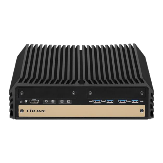
Page 14: Product Pictures
2x PCI/PCIe Slots for Add-on Cards (Maximum Length: 235mm) (For DS-1201 & DS-1202 only) ⚫ 4x CMI Slots for Modular I/O Expansions ⚫ 1x CFM Slot for Power Ignition Sensing Function ⚫ Wide Operating Temperature (-40°C to 70°C ) ⚫ EN50155 (EN50121-3-2) / EN60950-1 Certified DS-1200 Series | User Manual... -
Page 15: Hardware Specification
• EMC: CE, FCC Class A • 3x mSATA (shared by Mini-PCIe socket) (Gen3), BIOS Selectable • Safety: LVD, EN60950-1 • 1x M.2 Key M 2280 Socket, Supports PCIe x4 NVMe SSD or SATA SSD (Gen3) • Railway: EN50155, EN50121-3-2 DS-1200 Series | User Manual... -
Page 16: System I/O
HDD LED Removable HDD Bay Indicates the status of the hard drive Used to inserts a SIM card, CMOS battery, and Digital I/O LED 2.5” HDD Indicates the working status of digital input/ output DS-1200 DS-1200 Series | User Manual... - Page 17 DS-1201 DS-1202 DS-1200 Series | User Manual...
-
Page 18: Rear
Used to connect a monitor with DisplayPort interface A terminal block used to connect to remote USB 3.0 Port power on/off switch Universal I/O Bracket Used to connect USB 3.0/2.0/1.1 device Used to customized I/O output DS-1200 DS-1200 Series | User Manual... - Page 19 DS-1201 DS-1202 DS-1200 Series | User Manual...
-
Page 20: Mechanical Dimension
1.7 Mechanical Dimension DS-1200 Unit: mm DS-1201 Unit: mm DS-1200 Series | User Manual... - Page 21 DS-1202 Unit: mm DS-1200 Series | User Manual...
- Page 22 Chapter 2 Switches & Connectors DS-1200 Series | User Manual...
-
Page 23: Location Of Switches And Connectors
2.1 Location of Switches and Connectors 2.1.1 Top View DS-1200 Series | User Manual... -
Page 24: Bottom View
2.1.2 Bottom View DS-1200 Series | User Manual... -
Page 25: Switches And Connectors Definition
Mini PCI-Express Socket + mSATA + 4G Module CN3, CN4 Mini PCI-Express / mSATA Socket M.2 PCIE / SATA SSD USB2_13_1 Internal USB 2.0 Ports PCIE1 PCI-Express X1 Socket PCIE2 PCI-Express X16 Socket SODIMM1, SODIMM2 DDR4 SODIMM Socket DS-1200 Series | User Manual... -
Page 26: Definition Of Switches
SATA DOM Function Setting: Pin Define SW1 Switch Switch mode Function Disable SATA DOM Enable (Default) COM1/2 Voltage Function Setting: Pin Define SW1 Switch Switch Function mode 0V(RI) ON/ON (Default) COM1 ON/OFF OFF/OFF 0V(RI) ON/ON (Default) COM2 ON/OFF OFF/OFF DS-1200 Series | User Manual... -
Page 27: Definition Of Connectors
+1.5V 46 NA 11 REFCLK- 47 NA 12 SIM_CLK SMB_CLK 48 +1.5V PETN/SATATN 49 NA REFCLK+/SIM_PWR2 14 SIM_Reset1 SMB_DATA 50 GND 15 GND PETP/SATAPN 51 NA 16 SIM_VPP1 52 +3.3V 17 SIM_CLK2 18 GND USB_D- DS-1200 Series | User Manual... - Page 28 46 NA 11 NA 47 NA 12 NA SMB_CLK 48 +1.5V 13 NA PETN/SATATXN 49 NA 14 NA SMB_DATA 50 GND 15 GND PETP/SATATXP 51 NA 16 NA 52 +3.3V 17 NA 18 GND USB_D- DS-1200 Series | User Manual...
- Page 29 46 NA 11 REFCLK- 47 NA 12 NA SMB_CLK 48 +1.5V 13 REFCLK+ PETN/SATATN 49 NA 14 NA SMB_DATA 50 GND 15 GND PETP/SATATP 51 NA 16 NA 52 +3.3V 17 NA 18 GND USB_D- DS-1200 Series | User Manual...
- Page 30 SMD_DATA SUSCLK 17 PERN2 PERP0/SATARN0 69 PEDET 18 +3.3V ALERT# +3.3V 19 PERP2 20 NC +3.3V 21 CFG0 PETN0/SATATN0 73 22 NC +3.3V 23 PETN2 PETP0/SATATP0 75 CFG2 24 NC RESET# 25 PETP2 26 NC DS-1200 Series | User Manual...
- Page 31 LED Color HDD LED HDD Read/Write Blinking Yellow System Temp ≤ 65°C Colorless 65°C < System Temp ≤ 70°C Blue TEMP GPIO TEMP LED 70°C < System Temp ≤ 75°C 75°C < System Temp Blinking Red DS-1200 Series | User Manual...
- Page 32 CN7: Remote Power on/off, Remote Reset Switch Connector Connector Type: Terminal Block 2X2 4-pin, 3.5mm pitch Definition PWR_SW RESET_SW Note: DO NOT apply power to this CONNECTOR!!! This port is used to connect a SWITCH!!! DS-1200 Series | User Manual...
- Page 33 COM1_2_1: RS232 / RS422 / RS485 Connector Connector Type: 9-pin D-Sub RS422 / 485 RS485 RS232 Full Duplex Half Duplex Definition Definition Definition DATA - DATA + DS-1200 Series | User Manual...
-
Page 34: Chapter 3 System Setup
Chapter 3 System Setup DS-1200 Series | User Manual... -
Page 35: Removing The Top Cover
1. Turn over the unit to have the bottom side face up, loosen the 6 screws on the bottom cover and place them aside for later use. 2. Remove the bottom cover from the chassis. DS-1200 Series | User Manual... - Page 36 3. Unscrew the 2 screws at rear panel as marked on the photo and place them aside for later use. 4. Loosen the 4 screws. Pull out 4 latches as marked on the photo. DS-1200 Series | User Manual...
- Page 37 5. Lift up the unit vertically by holding the front and rear panel. 6. Turn over the body of the unit and place it gently. DS-1200 Series | User Manual...
-
Page 38: Installing Cpu
3.2 Installing the CPU Locate the CPU socket, remove the protection cover on it. Press the CPU socket lever and pull it aside away from the socket to unlock it. Pull back the lever to open the socket. DS-1200 Series | User Manual... - Page 39 Align the notches on CPU with the alignment post on socket. The notches of socket provide the space for fingers while lowering the CPU, hold the CPU by the edges toward the notches and insert the CPU gently. DS-1200 Series | User Manual...
- Page 40 Note: Before putting on the heatsink (in the next step), please make sure the protective film on the Thermal Pad has been removed! Align mounting holes of heatsink with the nut studs and fasten the heat sink with provided 4 screws. DS-1200 Series | User Manual...
-
Page 41: Installing So-Dimm Memory
Note: Before assembling the system’s chassis cover, please make sure the protective film on the Thermal Pad has been removed! 3.3 Installing SO-DIMM Memory 1. Locate the SO-DIMM sockets at the bottom side of system. Unscrews the 4 screws and remove the bracket. DS-1200 Series | User Manual... - Page 42 2. Locate two SO-DIMM sockets at the bottom. 3. Tilt the SO-DIMM module at a 45-degree angle and insert it to SO-DIMM socket until the gold-pated connector of module contacted firmly with the socket. 45° 45° Upper socket Lower socket DS-1200 Series | User Manual...
- Page 43 4. Press the modules down until it’s fixed firmly by the two locking latches on the sides. 5. Put the cover back and fix the cover with 4 screws. DS-1200 Series | User Manual...
-
Page 44: Installing A Mini-Pcie/Msata Card On Top Side
Locate the Mini PCIe socket on the top side of system. Use provided two screws fasten the half size module and adapter bracket together as shown in Fig (a) below. (b) Full Size Mini-PCIe Card (a) Half Size Mini-PCIe Card DS-1200 Series | User Manual... - Page 45 Insert the Mini-PCIe card at a 45-degree angle until its edge connector is connected firmly into slot. 45° Press down the module and fasten two screws to secure the module. DS-1200 Series | User Manual...
-
Page 46: Installing A Mini-Pcie/Msata Card On Bottom Side
1. Turn over the body of the unit. Locate Mini-PCIe (mSATA) slots at the bottom. 2. Tilt the Mini-PCIe module at a 45-degree angle and insert it to the slot until the gold-pated connector of module contacted firmly with the slot. 45° DS-1200 Series | User Manual... -
Page 47: Installing Antennas
3. Press down the module and use previous two screws to fix the module. 3.6 Installing Antennas 1. Remove the antenna rubber covers on rear panel. DS-1200 Series | User Manual... - Page 48 2. Have antenna jack penetrate through the hole. 3. Put on washer and fasten the nut with antenna jack. 4. Assemble the antenna and antenna jack together. DS-1200 Series | User Manual...
- Page 49 5. Attach the RF connector at another end of cable onto the module. DS-1200 Series | User Manual...
-
Page 50: Installing A Sata Hard Drive On Top Side
2. Make the PCB side of the HDD face up, place the HDD bracket on it. Ensure the direction of bracket is correct and use 4 provided screws to assemble HDD and HDD bracket together. DS-1200 Series | User Manual... - Page 51 3. Turn over the HDD bracket. Connect the HDD bracket to the SATA connector and fasten the 3 screws. DS-1200 Series | User Manual...
-
Page 52: Installing An M.2 Card
3.8 Installing an M.2 Card 1. Turn over the body of the unit. Unscrews the 2 screws and remove the bracket. Locate M.2 slots at the bottom. DS-1200 Series | User Manual... - Page 53 3. Tilt the Mini-PCIe module at a 45-degree angle and insert it to the slot until the gold-pated connector of module contacted firmly with the slot. 4. Press down the module and use previous one screw to fix the module. DS-1200 Series | User Manual...
-
Page 54: Installing A Pci/Pcie Add-On Card (For Ds-1201 And Ds-1202 Only)
3.9 Installing a PCI/PCIe Add-on Card (For DS-1201 and DS-1202 only) The applicable riser cards for DS-1200 series are listed in the following table. Model No. Description Compatible Model RC-E16-01 Riser Card 1 x PCIex16 DS-1201 RC-PI-01 Riser Card 1 x PCI... - Page 55 2. Unscrew the 4 screws to remove the extension bracket. 3. Remove the extension bracket from the system. DS-1200 Series | User Manual...
- Page 56 4. Assemble the riser card with extension bracket together and fasten with the 4 screws. 5. (1) Loosen the screw to remove I/O bracket. (2) Loosen the 2 screws halfway to allow the card retainer to be adjustable. DS-1200 Series | User Manual...
- Page 57 6. (1) Insert a PCI(e) add-on card to the slot. (2) Fasten the screw to secure it (3) Push the card retainer forward to against the edge of the add-on card. (4) Tighten the screw to fix the card retainer. 7. Locate the riser card slot on bottom side of system. DS-1200 Series | User Manual...
- Page 58 8. Install the module assembled in step 4 into the riser card slot, and fasten the 4 screws to secure it. DS-1200 Series | User Manual...
-
Page 59: Assembling The System
1. Make sure the notch on chassis and the front bezel of body are at the same side. 2. Lift up the body of unit. Make sure that both front and rear panels are in the chassis groves and assemble the body on to chassis firmly. DS-1200 Series | User Manual... - Page 60 3. Push into the 4 latches as indicated and fasten the 4 screws. 4. Fasten the 2 screws at rear panel. DS-1200 Series | User Manual...
- Page 61 5. Be sure to align the grooves with front and rear panels. Put the cover back on and fasten the 6 screws to fix the cover. DS-1200 Series | User Manual...
-
Page 62: Installing A Sata Hard Drive At Front Side
3.11 Installing a SATA Hard Drive at Front Side 1. Loosen the screws in order to remove the front expansion plate. 2. Locate the removable HDD bay and loosen the screw. DS-1200 Series | User Manual... - Page 63 4. Make the PCB side of the HDD face up, place the HDD bracket into it. Ensure the direction of bracket is correct and use 4 provided screws to assemble HDD and HDD bracket together. DS-1200 Series | User Manual...
- Page 64 5. Align the HDD bracket with the entrance of HDD bay. Holding the rotating arm and insert the HDD bracket until the connector of HDD contact the SATA connector firmly. 6. Place the rotating arm back and fasten the screw. DS-1200 Series | User Manual...
-
Page 65: Installing A Sim Card
3.12 Installing a SIM Card 1. Locate the SIM card slot at front side. 2. Insert the SIM card according to the icon instruction aside. SIM 1 SIM 2 DS-1200 Series | User Manual... -
Page 66: Installing The Cmos Battery
3.13 Installing the CMOS Battery 1. Locate the removable CMOS Battery and loosen the screw. 2. Pull out the CMO S battery bracket with assistance of a tweezer. DS-1200 Series | User Manual... - Page 67 3. Insert a CMOS battery in the battery slot. 4. Insert the battery bracket firmly and fasten the screw. DS-1200 Series | User Manual...
-
Page 68: Fastening The Cover
3.14 Fastening the Cover 1. Fasten the cover by using the two screws. DS-1200 Series | User Manual... -
Page 69: Wall Mount Brackets
3.15 Wall Mount Brackets DS-1200 series offers wall mount that customers can install system on the wall in convenient and economical ways. 1. The mounting holes are at the bottom of system. Use provided 8 screws to fasten the bracket with each side of system together. - Page 70 2. Fasten the screws through the bracket mounting hole to mount system on the wall. DS-1200 Series | User Manual...
-
Page 71: Chapter 4 Bios Setup
Chapter 4 BIOS Setup DS-1200 Series | User Manual... -
Page 72: Bios Introduction
You can use arrow keys ( ↑↓ ) to highlight the field and press <Enter> to call up the sub-menu. Then you can use the control keys to enter values and move from field to field within a sub-menu. If you want to return to the main menu, just press the <Esc >. DS-1200 Series | User Manual... -
Page 73: Main Setup
Use arrow keys to move among the items and press <Enter> to accept or enter a sub-menu. 4.2.1 System Date Set the date. Please use <Tab> to switch between date elements. 4.2.2 System Time Set the time. Please use <Tab> to switch between time elements. DS-1200 Series | User Manual... -
Page 74: Advanced Setup
Virtualization Technology will allow a platform to run multiple operating systems and applications in independent partitions. With virtualization, one computer system can function as multiple virtual systems. ■ Active Process Cores [All] Allows you to choose the number of active processor cores. DS-1200 Series | User Manual... -
Page 75: Sata Configuration
Enables or disables SATA Port 3. ■ Serial ATA Port 4 ❑ Port 4 [Enabled] Enables or disables SATA Port 4. ■ Serial ATA Port 5 ❑ Port 5 [Enabled] Enables or disables SATA Port 5. DS-1200 Series | User Manual... -
Page 76: Pch-Fw Configuration
Enables or disables BIOS support for security device. ■ SHA-1 PCR Bank [Enabled] Enables or disables SHA-1 PCR (Platform Configuration Register) Bank. ■ SHA256 PCR Bank [Enabled] Enables or disables SHA256 PCR (Platform Configuration Register) Bank. DS-1200 Series | User Manual... -
Page 77: Acpi Settings
Allows users to select the highest Advanced Configuration Power Interface® (ACPI) sleep state that system will enter when suspend button is pressed. [Suspend Disabled]: Disables entering suspend state. [S3 (suspend to RAM)]: Enables suspend to RAM state. DS-1200 Series | User Manual... -
Page 78: F81866 Super Io Configuration
Allows you to change the IO Address & IRQ settings of the specified serial port. ❑ Onboard Serial Port 1~6 Mode [RS232] Allows you to select Serial Port Mode. Configuration options: [RS232] [RS422/RS485 Full Duplex] [RS485 Half Duplex] ■ Watch Dog [Disabled] Enables or disables watch dog function. DS-1200 Series | User Manual... -
Page 79: Hardware Monitor
■ External Smart Fan Configuration Allows users to setting external smart fan parameters. ■ Internal Smart Fan Function [Enabled] Enables or disables internal smart fan function. ■ Internal Smart Fan Configuration Allows users to setting internal smart fan parameters. DS-1200 Series | User Manual... -
Page 80: S5 Rtc Wake Settings
4.3.9 Serial Port Console Redirection ■ Console Redirection Allow users to enable or disable COM0, COM1, COM2, COM3, COM4, COM5 console redirection function. COM0 = Serial Port 1 COM1 = Serial Port 2 COM2 = Serial Port 3 DS-1200 Series | User Manual... -
Page 81: Usb Configuration
Enables or disables XHCI (USB3.0) hand-off function. Use this feature as a workaround for operating systems without XHCI hand-off support. ■ USB Mass Storage Driver Support [Enabled] Enables or disables USB mass storage driver support. DS-1200 Series | User Manual... -
Page 82: Network Stack Configuration
[UEFI and Legacy]: Allows booting from operating systems that support legacy option ROM or UEFI option ROM. [Legacy only]: Allows booting from operating systems that only support legacy option ROM. [UEFI only]: Allows booting from operating systems that only support UEFI option ROM. DS-1200 Series | User Manual... -
Page 83: Nvme Configuration
[Legacy]: Enables legacy option ROM only. ■ Other PCI devices [Do not launch] Allows users to determine option ROM execution policy for devise other than network, storage, or video. 4.3.13 NVMe Configuration This screen displays the current NVMe device information. DS-1200 Series | User Manual... -
Page 84: Chipset Setup
This feature sets the maximum TOLUD (Top of Low Usable DRAM) value, which specifies the TOLUD memory space to be used by internal graphics devices, GTT Stolen Memory, and TSEG, respectively, if these devices are enabled. DS-1200 Series | User Manual... -
Page 85: Pch-Io Configuration
Configuration options: [Auto] [IGFX] [PEG] [PCIe] ❑ Internal Graphics [Auto] Allows users to enable or disable Internal Graphics. Configuration options: [Auto] [Disabled] [Enabled] ■ VT-d [Enabled] Enables or disables Intel® Virtualization Technology for Directed I/O (VT-d) capability. 4.4.2 PCH-IO Configuration DS-1200 Series | User Manual... - Page 86 Enables or disables PCI Express Root Port 1. ❑ PCIeSpeed [Auto] Allows you to select PCI Express port speed. Configuration options: [Auto] [Gen1] [Gen2] [Gen3]. ■ LAN i219LM Controller [Enabled] Enables or disables i219LM LAN Controller. DS-1200 Series | User Manual...
- Page 87 Allows you to specify which power state system will enter when power is resumed after a power failure (G3 state). [Always on]: Enters to power on state. [Always off]: Enters to power off state. [Keep last state]: Enters to the last power state before a power failure. DS-1200 Series | User Manual...
-
Page 88: Security Setup
This section allows users to configure BIOS security settings. 4.5.1 Administrator Password Administrator Password controls access to the BIOS Setup utility. 4.5.2 User Password User Password controls access to the system at boot and to the BIOS Setup utility. DS-1200 Series | User Manual... -
Page 89: Boot Setup
Allows you to enable or disable Fast Boot function. If enabled, system boots with initialization of a minimal set of devices required to launch active boot option. ■ Hard Drive BBS Priority Allows you to set the order of the legacy devices in this group. DS-1200 Series | User Manual... -
Page 90: Save & Exit
■ Save as User Defaults This item allows you to save the changes done so far as user defaults. ■ Restore User Defaults This item allows you to restore the user defaults to all the setup options. DS-1200 Series | User Manual... -
Page 91: Chapter 5 Product Application (For Dio Only)
Chapter 5 Product Application (For DIO only) DS-1200 Series | User Manual... -
Page 92: Digital I/O (Dio) Application
GPIO32 (PIN 38) GPIO42 (PIN 46) GPIO33 (PIN 39) GPIO43 (PIN 47) GPIO34 (PIN 40) GPIO44 (PIN 48) GPIO35 (PIN 41) GPIO45 (PIN 49) GPIO36 (PIN 42) GPIO46 (PIN 50) GPIO37 (PIN 43) GPIO47 (PIN 51) DS-1200 Series | User Manual... - Page 93 Following is an example to enable configuration and to disable configuration by using debug. -o 4e 87 -o 4e 87 (enable configuration) -o 4e aa (disable configuration) 5.1.1.4 Relative Registers To program the F81866A configuration registers, see the following configuration procedures. DS-1200 Series | User Manual...
- Page 94 DS-1200 Series | User Manual...
- Page 95 DS-1200 Series | User Manual...
- Page 96 DS-1200 Series | User Manual...
- Page 97 <Output/Input Mode Selection> // Set GP80 to GP87 output Mode WriteByte(AddrPort, 0x88) // Select configuration register 88h WriteByte(DataPort, 0xXF)) // Set (bit 0~7) = 1 to select GP 80 ~87 as Output mode. <Output Value> DS-1200 Series | User Manual...
- Page 98 // Select configuration register 82h ReadByte(DataPort, Value) // Read bit 0~7(0xFx)= GP70~77 as High <input Value> WriteByte(AddrPort, 0xC2) // Select configuration register C2h ReadByte(DataPort, Value) // Read bit 0~7(0xFx)= GP30~37 as High <Leave the Extended Function Mode> WriteByte(AddrPort, 0xAA) DS-1200 Series | User Manual...
- Page 99 WriteByte(AddrPort, 0xAA) 5.1.1.5 Change base address <Enter the Extended Function Mode> WriteByte(AddrPort, 0x87) WriteByte(AddrPort, 0x87) // Must write twice to enter Extended mode <Select Logic Device> WriteByte(AddrPort, 0x07) WriteByte(dataPort, 0x06) // Select logic device 06h DS-1200 Series | User Manual...
- Page 100 // Select configuration register 60h (High Byte address) WriteByte(DataPort, (0x0A)) WriteByte(AddrPort, 0x61) // Select configuration register 61h (Low Byte address) WriteByte(DataPort, (0x00)) <Leave the Extended Function Mode> WriteByte(AddrPort, 0xAA) Cincoze default GPIO Port base address is 0xA00h DS-1200 Series | User Manual...
- Page 101 = DI6 = DO6 (Base Base address address +3) +2) (0xA02) (0xA03) = DI7 = DO7 (Base Base address address +3) +2) (0xA02) (0xA03) = DI8 = DO8 (Base Base address address +3) +2) (0xA02) (0xA03) DS-1200 Series | User Manual...
- Page 102 = DI14 = DO14 (Base Base address address +9) +10) (0xA10) (0xA09) = DI15 = DO15 (Base Base address address +9) +10) (0xA10) (0xA09) = DI16 = DO16 (Base Base address address +9) +10) (0xA10) (0xA09) DS-1200 Series | User Manual...
- Page 103 0xA02 Pin Definition DI16 DI15 DI14 DI13 DI12 DI11 DI10 Data Bits Digital Input I/O Port Address 0xA09 Pin Definition DO16 DO15 DO14 DO13 DO12 DO11 DO10 Data Bits Digital Output I/O Port Address 0xA010 DS-1200 Series | User Manual...
-
Page 104: Digital I/O (Dio) Hardware Specification
DO Signal have to pull up resistor to XCOM+ for external device, the resistance will affect the pull up current Signal High Level: Pull up resistor to XCOM+ Signal Low Level: = XCOM- Sink Current: 1A (Max) DS-1200 Series | User Manual... -
Page 105: Dio Connector Definition
5.2.1 DIO Connector Definition DIO1: Digital Input / Output Connector Connector Type: Terminal Block 2X5 10-pin, 3.5mm pitch Definition Definition XCOM+ XCOM- (DC INPUT) (GND) Definition Definition 2XCOM+ 2XCOM- (DC INPUT) (GND) Reference Input Circuit DS-1200 Series | User Manual... - Page 106 Connector Type: Terminal Block 2X5 10-pin, 3.5mm pitch Definition Definition (DI9) (DO9) (DI10) (DO10) (DI11) (DO11) (DI12) (DO12) XCOM+ XCOM- (DC INPUT) (GND) Definition Definition (DI13) (DO13) (DI14) (DO14) (DI15) (DO15) (DI16) (DO16) 2XCOM+ 2XCOM- (DC INPUT) (GND) Reference Output Circuit DS-1200 Series | User Manual...
- Page 107 Chapter 6 Optional Modules Pin Definitions and Settings DS-1200 Series | User Manual...
- Page 108 4x DB9 Cutout for DS-1200 Series CMI Module with 4x Electrical Isolated RS-232/422/485 Serial Ports, CMI-ICOM01/UB1004 1x Universal Bracket with 4x DB9 Cutout for DS-1200 Series COM3/COM4/COM5/COM6: RS232 / RS422 / RS485 Connector Connector Type: 9-pin D-Sub RS422 / 485...
-
Page 109: Cmi-M12 Connector Definition And Settings
Product Description CMI-M12LAN01-R12 CMI Module with 4x Intel I210-IT GbE LAN, M12 Connector / 1x /UB1010 Universal Bracket with 4x M12 Cutout for DS-1200 Series CMI-M12LAN01-R12 Connector CMI-M12 LAN Module Pin Definitions Connector Type: M12 A coded 8pin connector Definition... -
Page 110: Cmi-Com Connector Definition And Settings
1 minute 5 minutes 10 minutes 30 minutes 1 hour 2 hours Reserved (0 second) 24V_12V_1: 12V / 24V Car Battery Switch Definition 1-2 (Right) 24V Car Battery Input 2-3 (Left) 12V Car Battery Input DS-1200 Series | User Manual... -
Page 111: Installing A Low Speed Cmi Module
6.4 Installing a Low Speed CMI Module The applicable low speed CMI modules for DS-1200 series are listed in the following table. Model No. Product Description CMI Module with 4x RS232/422/485 Serial Ports, 1x Universal Bracket CMI-COM02/UB1004 with 4x DB9 Cutout for DS-1200 Series... - Page 112 2. Locate the connector of CMI-module on the top side of system. 3. Insert the CMI module carefully into the CMI connector on the main board. Fix it with 4 screws. DS-1200 Series | User Manual...
- Page 113 4. Fasten the 2 hex nuts from the back side of front bezel. 5. Fasten the 8 D-Sub jack screws as marked on photo. DS-1200 Series | User Manual...
-
Page 114: Installing A High Speed Cmi Module
6.5 Installing a High Speed CMI Module The applicable high speed CMI modules for DS-1200 series are listed in the following table. Model No. Product Description CMI Module with 4x Intel I210-IT GbE LAN, RJ45 Port / 1x Universal CMI-LAN01-R12/UB1012... - Page 115 3. Remove the 4 ring nuts from M12 jack before attempting to install the module. 4. Insert the CMI module vertically into the female connector on system’s mainboard until it’s connected firmly and fasten 4 screws to fix it. DS-1200 Series | User Manual...
- Page 116 5. Attach the M12 I/O bracket. 6. Fasten 2 hex nuts from the back side of the bracket. 7. Fasten the 4 ring nuts onto M12 jacks. DS-1200 Series | User Manual...
-
Page 117: Installing A Cfm-Poe Module
2_LAN1_3-(Power PIN) If you use CMI-LAN01-R12 Module, please paste the shading tape to the place which was marked by red frame. If you use CMI-M12LAN01-R12 Module please skip this step. (Note: Please don’t block the LED.) DS-1200 Series | User Manual... - Page 118 1. Insert the CMI module vertically into the female connector on system’s mainboard until it’s connected firmly and fasten 4 copper pillars to fix it. 2. Insert the CFM-PoE module vertically into the female connector on CMI module until it’s connected firmly. DS-1200 Series | User Manual...
- Page 119 5. Please paste the 1 thermal pad onto the coil of the CFM-PoE module carefully. Note: Before putting on the heatsink (in the step 6), please make sure the protective film on the Thermal Pad been removed! DS-1200 Series | User Manual...
- Page 120 6. Please paste the heatsink onto the CFM-PoE module carefully. 7. Fasten 4 screws to fix it. DS-1200 Series | User Manual...
- Page 121 8. Please paste the thermal pad onto the heatsink carefully. Note: Before assembling the system’s chassis cover, please make sure the protective film on the Thermal Pad has been removed! DS-1200 Series | User Manual...
-
Page 122: Installing A Cfm-Ign Power Ignition Module
6.7 Installing a CFM-IGN Power Ignition Module 1. Locate power ignition connector on main board. 2. Insert the power ignition module carefully into the connector on main board. Fasten 2 screws to fix it. DS-1200 Series | User Manual... - Page 123 1. Prepare an external fan. Loosen the 2 screws halfway on mounting frame before attempting to install it. 2. Slide the FAN into the middle groove of chassis as illustrated. Tighten the 2 screws to fix it onto chassis. DS-1200 Series | User Manual...
- Page 124 3. Move the fan to the center of chassis. Tighten the 2 screws marked on photo to secure it. 4. Connect the FAN cable to external fan power connector at rear panel. DS-1200 Series | User Manual...
-
Page 125: Installing An External Fan
Inhaling Fan with 4pin Connector, Universal Bracket 1. Unscrew 6 screws to remove 3 I/O brackets from rear panel. 2. Attach the FAN from back side of rear panel. Fasten 4 screws to fix it. DS-1200 Series | User Manual... - Page 126 3. Connect the FAN power cable to the power connector on main board.as marked on photo. DS-1200 Series | User Manual...
- Page 127 © 2020 Cincoze Co., Ltd. All rights reserved. The Cincoze logo is a registered trademark of Cincoze Co., Ltd. All other logos appearing in this catalog are the intellectual property of the respective company, product, or organization associated with the logo.
Need help?
Do you have a question about the DS-1200 Series and is the answer not in the manual?
Questions and answers