Sign In
Upload
Download
Table of Contents
Contents
Add to my manuals
Delete from my manuals
Share
URL of this page:
HTML Link:
Bookmark this page
Add
Manual will be automatically added to "My Manuals"
Print this page
×
Bookmark added
×
Added to my manuals
Manuals
Brands
Life Fitness Manuals
Elliptical Trainer
INXSC
Assembly instructions manual
Life Fitness INXSC Assembly Instructions Manual
Integrity cross-trainer
Hide thumbs
Also See for INXSC
:
Service manual
(35 pages)
1
2
3
4
Table Of Contents
5
6
7
8
9
10
11
12
13
14
15
16
17
18
19
20
21
22
23
24
25
26
27
28
29
30
31
32
33
34
35
36
page
of
36
Go
/
36
Contents
Table of Contents
Troubleshooting
Bookmarks
Table of Contents
Table of Contents
Getting Started
Safety Instructions
Consignes de
Sécurité
Where to Place and How to Stabilize the Cross-Trainer
Electrical Power Requirements
Supply)
Power
Product Overview
INXDX, Club Series +, INT-XT (Deluxe), INT-XT- CS, INT-XT-CS-B1, INT-XT-B1
Inxsx, Inxsc, Int-Xt, Pf-Int-Xt
Inxsse, Inxst, Int-Xt
(Deluxe)
Int-Xt-B1
INXDSE, INXDST, Club Series +, INT-XT (Deluxe), INT-XT-CS, INT-XT-CS-B1, INT-XT- B1 (Deluxe)
Connections
How to Use the Mounting and Dismounting the
Cross-Trainer
Service and Technical Data
Approved and Compatible
Tips
Cleaners
Troubleshooting the Polar
Strap
Schedule
Troubleshoot the Lifepulse
Recycle the How to Obtain Product
Sensors
Battery
Service
Assembly: INXSC, INXSX, INXDX, INXSSE
Hardware and Required
Attach Bullhorn
Tools
Attach Moving
Attach Console Support
Handles
Weldment
Insert Cup Holder
Shrouds
Shroud
Covers
Base to Console Cable Connections - Integrity X or Integrity C
Base to Console Cable Connections - Discover SE3 / SE3 HD / ST
Attach Console
Assembly
Tools
Before You Begin
Attach Bullhorn
Attach Moving Handles
Attach Upper Right and Left
Attach Middle Shroud
Insert Cup Holder
Shrouds
Attach Deadshaft
Covers
Assembly: INT-XT, PF-INT-XT, INT-XT-CS
Assembly: INT-XT-B1, INT-XT-CS-B1
Hardware and Required
Tools
Before You Begin
Attach Bullhorn
Attach Moving Handles
Attach Upper Right and Left
Attach Middle Shroud
Insert Cup Holder
Shrouds
Attach Deadshaft
Covers
Base to Console Cable Connections - Integrity X or Integrity C
Base to Console Cable Connections - Discover SE3 / SE3 HD / ST
Attach Console
Assembly
Specifications
Advertisement
Quick Links
1
Electrical Power Requirements
2
Power
3
Inxdx, Club Series +, Int-Xt (Deluxe), Int-Xt- Cs, Int-Xt-Cs-B1, Int-Xt-B1
4
Troubleshooting the Polar
5
Battery
6
Troubleshoot the Lifepulse
7
Service
Download this manual
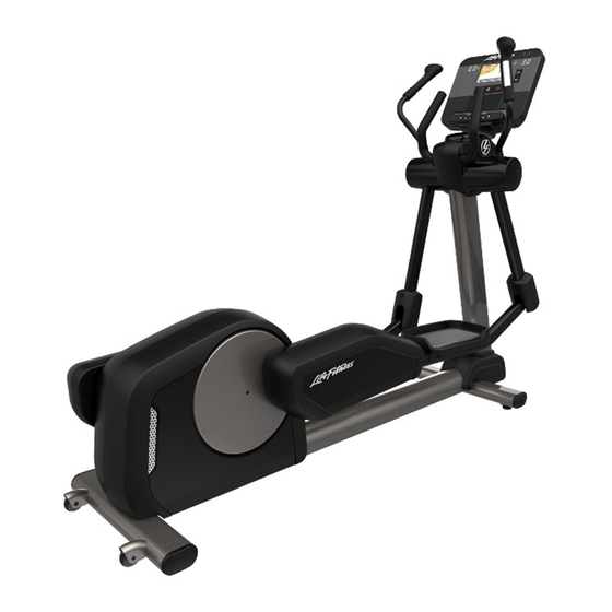
INTEGRITY CROSS-TRAINER
INXSC, INXSX, INXDX, INXSSE, INXST, INXDSE, INXDST, CLUB SERIES +,
INT-XT, PF-INT-XT, INT-XT-CS, INT-XT-B1, INT-XT-CS-B1
Assembly Instructions
1006908-0001 REV AE
Table of
Contents
Previous
Page
Next
Page
1
2
3
4
5
Advertisement
Table of Contents
Need help?
Do you have a question about the INXSC and is the answer not in the manual?
Ask a question
Questions and answers
Related Manuals for Life Fitness INXSC
Fitness Equipment Life Fitness CLUB Series Service Manual
Integrity cross-trainer (35 pages)
Elliptical Trainer Life Fitness INXS-SLXX Assembly Instructions Manual
Integrity cross-trainer (38 pages)
Fitness Equipment Life Fitness INTEGRITY AND CLUB PLUS Series Assembly Instructions Manual
Cross-trainer (34 pages)
Elliptical Trainer Life Fitness M051-00K68-A035 Operation Manual
Integrity series summit trainer (clsl) (44 pages)
Elliptical Trainer Life Fitness 8500 Service Manual
Total body cross-trainers with rear drive system (101 pages)
Elliptical Trainer Life Fitness X 35 User Manual
Total-body elliptical cross-trainer (44 pages)
Elliptical Trainer Life Fitness X3 Owner's Manual
Total-body elliptical cross-trainer (27 pages)
Elliptical Trainer Life Fitness 95Xi Operation Manual
Life fitness operation manual total body trainer 95xi (38 pages)
Elliptical Trainer Life Fitness E1 Service Manual
Total-body elliptical cross-trainers (41 pages)
Elliptical Trainer Life Fitness Base X3 Basic User Manual
Total-body elliptical cross-trainer (39 pages)
Elliptical Trainer Life Fitness CT9500 Parts Manual
Cross-trainer (17 pages)
Elliptical Trainer Life Fitness 9500 Series Service Manual
Cross-trainers (79 pages)
Elliptical Trainer Life Fitness X 5 User Manual
Total-body elliptical cross-trainer (23 pages)
Elliptical Trainer Life Fitness X5 Assembly & Operation Manual
X series cross-trainer (28 pages)
Elliptical Trainer Life Fitness FS6 Operation Manual
Fs console cross-trainers (36 pages)
Elliptical Trainer Life Fitness CT9100 General Assembly
(18 pages)
This manual is also suitable for:
Inxsx
Inxdx
Inxsse
Inxst
Inxdse
Inxdst
...
Show all
Club series +
Int-xt
Pf-int-xt
Int-xt-cs
Int-xt-b1
Int-xt-cs-b1
Table of Contents
Print
Rename the bookmark
Delete bookmark?
Delete from my manuals?
Login
Sign In
OR
Sign in with Facebook
Sign in with Google
Upload manual
Upload from disk
Upload from URL


Need help?
Do you have a question about the INXSC and is the answer not in the manual?
Questions and answers