
Related Manuals for Life Fitness INXS-SLXX


Summary of Contents for Life Fitness INXS-SLXX
- Page 1 INTEGRITY CROSS-TRAINER INXS-SLXX, INXD-SLXX, INT-XT, PF-INT-XT, INT-XT-CS, INT-XT-B1, INT-XT- CS-B1 Assembly Instructions 1015935-0001 REV AA...
- Page 3 Latin America and Caribbean* Spain Hong Kong Life Fitness, LLC Life Fitness IBERIA Life Fitness Asia Pacific LTD Columbia Centre III C/Frederic Mompou 5,1º1ª 32/F, Global Trade Square 9525 Bryn Mawr Avenue 08960 Sant Just Desvern Barcelona 21 Wong Chuk Hang Road Rosemont, IL 60018 U.S.A.
- Page 4 User and Service Documents Link https://lifefitness9512.zendesk.com/hc/en-us https://www.lftechsupport.com/web/document-library/documents Additional information is available online using the links above. أ علاه إل ر إبط باستخدإم إ لإ ن تر نت على إضافية معلومات تتوفر 点击上面的链接可在线获取更多信息。 Flere oplysninger er tilgængelige online gennem linket ovenfor. Bijkomende informatie is online beschikbaar via bovenstaande link.
-
Page 5: Table Of Contents
Polar Electro Inc. © Copyright 2021, Life Fitness, LLC. All Rights Reserved. Life Fitness, Hammer Strength, Cybex, ICG and SCIFIT are registered trademarks of Life Fitness, LLC and its affiliated companies and subsidiaries. Brunswick and related trademarks used under license from Brunswick Corporation. -
Page 6: Getting Started
1. Getting Started Safety Instructions Read all instructions before use. CAUTION: Any changes or modifications to this equipment could void the product warranty. WARNING: Health-related injuries may result from incorrect or excessive use of exercise equipment. Life Fitness STRONGLY recommends seeing a physician for a complete medical exam before undertaking an exercise program, particularly if the user has a family history of high blood pressure or heart disease, is over the age of 45, smokes, has high cholesterol, is obese, or has not exercised regularly in the past year. - Page 7 • Keep all loose clothing, shoelaces, and towels away from moving parts. • Do not reach into, or underneath, the unit or tip it on its side during operation. • This equipment is not intended for use by children. Keep children under the age of 14 away from the machine. •...
-
Page 8: Consignes De
AVERTISSEMENT : Une utilisation incorrecte ou excessive de l'appareil peut entraîner des blessures. Life Fitness Recommande VIVEMENT aux utilisateurs de passer un examen médical complet avant d'entamer un programme d'entraînement, et tout particulièrement dans les cas suivants : antécédents familiaux d'hypertension (pression sanguine trop élevée) ou de pathologies cardiaques, utilisateurs de 45 ans ou plus,... - Page 9 • Si certaines étiquettes d’avertissement sont manquantes ou endommagées, contactez immédiatement le service d’assistance à la clientèle. Nous vous en fournirons de nouvelles. Les étiquettes d’avertissement sont expédiées avec les appareils et doivent être installées avant utilisation de ces derniers. Life Fitness n’est pas responsable des étiquettes manquantes ou endommagées.
-
Page 10: Where To Place And How To Stabilize The Cross-Trainer
Where to Place and How to Stabilize the Cross-Trainer Read the entire manual before setting up the cross-trainer. After following all Safety Instructions, move the unit to the location where it will be used. Allow 1 ft. (0.3 m) of clearance in front of the cross-trainer and at least 2 ft. (0.6 m) on the side. -
Page 11: Electrical Power Requirements
The Integrity SL console is powered by a rechargeable 6-volt battery. Check the battery by pressing the GO button. The console should beep and light up. The console will display the Life Fitness logo. If a prompt doesn’t appear, mount the unit and begin pedaling. The console should light up and programming a workout should be possible. -
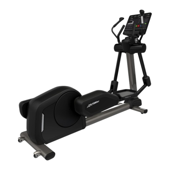
Page 12: Product Overview
2. Product Overview INXS-SLXX, INT-XT, PF-INT-XT, INT-XT-B1 Item Description Console Contact Heart Rate Sensors Cup Holder Pedal Leg Leveler Transport Wheels INXD-SLXX, INT-XT-CS, INT-XT-CS-B1, INT-XT (deluxe), INT-XT-B1 (deluxe) Item Description Console Contact Heart Rate Sensors Cup Holder Pedal Leg Leveler... -
Page 13: How To Use The Mounting And Dismounting The
How to Use the Cross-Trainer Place feet anywhere on the pedals that feel comfortable. Many users put their toes 1-2" from the front edge of the pedals and 0.5-1" from the inside edge of the pedals. However, the pedals are large enough to allow a range of foot positions depending on preference. -
Page 14: Service And Technical Data
3. Service and Technical Data Preventive Maintenance Tips NOTE: Safety of the equipment can be maintained only if the equipment is examined regularly for damage or wear. Keep the equipment out of use until defective parts are repaired or replaced. Pay special attention to parts that are subject to wear, as outlined below. -
Page 15: Troubleshooting The Polar
Preventive Maintenance Schedule Item Weekly Monthly Biannually Console Overlays Clean Inspect Bottle Holders / Accessory Clean Inspect Trays Console Mounting Bolts Inspect Hardware Inspect Frame Clean Inspect Plastic Covers Clean Inspect Lifepulse Sensors Clean / Inspect Leg Levelers Inspect / Adjust Pedals Clean Inspect... -
Page 16: Troubleshoot The Lifepulse
1. Verify the symptom and review the operating instructions. The problem may be unfamiliarity with the product and its features and workouts. 2. Locate and write down the serial number of the unit which is located on the top right of the front stabilizer. 3. Contact Life Fitness Customer Support Services at http://www.lifefitness.com. Page 14 of 35... -
Page 17: Assembly: Inxs-Slxx, Inxd-Slxx
4. Assembly: INXS-SLXX, INXD-SLXX Hardware and Required Tools Item Description Qty. M8 X 20 FLANGE HEX HEAD CAP SCREW M6 X 16 PHILLIPS PAN HEAD SCREW GROMMET M5 X 14 PHILLIPS PAN HEAD SCREW M4.2 X 10 PHILLIPS PAN HEAD SCREW M4.2 X 19 PHILLIPS PAN HEAD SCREW... -
Page 18: Attach Moving
Attach Moving Handles INXS-SLXX INXD-SLXX Run Heart Rate Cable down through the opening and Run Heart Rate Cable and Keypad Cable down through make connection. the opening and make connections. Item Description Qty. Handlebar, Left Handlebar, Right M8 Locknut 27 Nm (19.91 ft. lbs.) -
Page 19: Insert Cup Holder
Attach Upper Right and Left Shrouds NOTE: Check for proper clip engagement after installing the upper shrouds. Item Description Qty. Shroud: Upper, Right Shroud: Upper, Left M4.2 X 10 Phillips Pan Head Screw 1.5 Nm (13.3 in. lbs.) Attach Middle Shroud Item Description Qty. -
Page 20: Attach Deadshaft
Attach Deadshaft Covers 1. Secure rear deadshaft cover to rocker arm using one screw. Item Description Deadshaft Cover, Rear M6 X 16 Phillips Pan Head Screw 1.5 Nm (13.3 in. lbs.) 2. Add grommets to rear deadshaft cover. Interlock the front deadshaft cover into the rear deadshaft cover. Item Description Deadshaft Cover, Front... -
Page 21: Base To Console Cable Connections - Integrity Sl
Base to Console Cable Connections - Integrity SL Item Description CSAFE Base Switches, Lifepulse Base Power Base Com TV (optional) Attach Console - Integrity SL NOTE: Use the hook on top of the console support weldment to aid in console installation. Item Description Qty. -
Page 22: Attach Rear Console Shroud
Attach Rear Console Shroud Assembly 1. Insert grommets into the two holes on the back of the console support weldment. 2. Push the clips on top of the rear console shroud assembly into the corresponding slots on the console support weldment. -
Page 23: Assembly: Int-Xt, Pf-Int-Xt, Int-Xt-Cs
5. Assembly: INT-XT, PF-INT-XT, INT-XT-CS Hardware and Required Tools Item Description Qty. M8 X 20 FLANGE HEX HEAD CAP SCREW M6 X 16 PHILLIPS PAN HEAD SCREW GROMMET M4.2 X 10 PHILLIPS PAN HEAD SCREW M4.2 X 19 PHILLIPS PAN HEAD SCREW M8 LOCKNUT Required Tools: •... -
Page 24: Before You Begin
Before You Begin 1. The console support weldment with console attached is positioned with the console face down in the parts tray table packaging. Item Description Qty. Console Support Weldment Parts Tray Table Packaging CAUTION: Remove any protective covering / tape from the monocolumn and console support weldment prior to attaching to base! Failure to remove the protective covering can cause improper grounding! 2. -
Page 25: Attach Bullhorn
Attach Bullhorn Item Description Bullhorn M8 X 20 Flange Head Cap Screw 27 Nm (19.91 ft. lbs.) Attach Moving Handles INT-XT, PF-INT-XT INT-XT-CS, INT-XT (deluxe) Run Heart Rate Cable down through the opening and Run Heart Rate Cable and Keypad Cable down through make connection. -
Page 26: Attach Upper Right And Left
Attach Upper Right and Left Shrouds NOTE: Check for proper clip engagement after installing the upper shrouds. Item Description Qty. Shroud: Upper, Right Shroud: Upper, Left M4.2 X 10 Phillips Pan Head Screw 1.5 Nm (13.3 in. lbs.) Attach Middle Shroud Item Description Qty. -
Page 27: Covers
Attach Deadshaft Covers 1. Secure rear deadshaft cover to rocker arm using one screw. Item Description Deadshaft Cover, Rear M6 X 16 Phillips Pan Head Screw 1.5 Nm (13.3 in. lbs.) 2. Add grommets to rear deadshaft cover. Interlock the front deadshaft cover into the rear deadshaft cover. Item Description Deadshaft Cover, Front... -
Page 28: Tools
6. Assembly: INT-XT-B1, INT-XT-CS-B1 Hardware and Required Tools Item Description Qty. M8 X 20 FLANGE HEX HEAD CAP SCREW M6 X 16 PHILLIPS PAN HEAD SCREW GROMMET M5 X 14 PHILLIPS PAN HEAD SCREW M4.2 X 10 PHILLIPS PAN HEAD SCREW M4.2 X 19 PHILLIPS PAN HEAD SCREW M8 LOCKNUT Required Tools:... -
Page 29: Assembly: Int-Xt-B1, Int-Xt-Cs-B1 Hardware And Required Before You Begin
Before You Begin 1. The console support weldment is positioned face down in the parts tray table packaging. Item Description Qty. Console Support Weldment Parts Tray Table Packaging CAUTION: Remove any protective covering / tape from the monocolumn and console support weldment prior to attaching to base! Failure to remove the protective covering can cause improper grounding! 2. -
Page 30: Attach Bullhorn
Attach Bullhorn Item Description Bullhorn M8 X 20 Flange Head Cap Screw 27 Nm (19.91 ft. lbs.) Attach Moving Handles INT-XT-B1 INT-XT-B1 (deluxe), INT-XT-CS-B1 Run Heart Rate Cable down through the opening and Run Heart Rate Cable and Keypad Cable down through make connection. -
Page 31: Attach Upper Right And Left Attach Middle Shroud
Attach Upper Right and Left Shrouds NOTE: Check for proper clip engagement after installing the upper shrouds. Item Description Qty. Shroud: Upper, Right Shroud: Upper, Left M4.2 X 10 Phillips Pan Head Screw 1.5 Nm (13.3 in. lbs.) Attach Middle Shroud Item Description Qty. -
Page 32: Covers
Attach Deadshaft Covers 1. Secure rear deadshaft cover to rocker arm using one screw. Item Description Deadshaft Cover, Rear M6 X 16 Phillips Pan Head Screw 1.5 Nm (13.3 in. lbs.) 2. Add grommets to rear deadshaft cover. Interlock the front deadshaft cover into the rear deadshaft cover. Item Description Deadshaft Cover, Front... -
Page 33: Base To Console Cable Connections - Integrity Sl
Base to Console Cable Connections - Integrity SL Item Description CSAFE Base Switches, Lifepulse Base Power Base Com TV (optional) Attach Console - Integrity SL NOTE: Use the hook on top of the console support weldment to aid in console installation. Item Description Qty. -
Page 34: Assembly
Attach Rear Console Shroud Assembly 1. Insert grommets into the two holes on the back of the console support weldment. 2. Push the clips on top of the rear console shroud assembly into the corresponding slots on the console support weldment. -
Page 35: Specifications
7. Specifications Specifications Heavy / Commercial (INXS-SLXX, INXD-SLXX, INT-XT, PF-INT-XT, INT-XT-B1) EN ISO 20957 Class SA Designed Use Home (INT-XT-CS, INT-XT-CS-B1) EN ISO 20957 Class HA Maximum User Weight 400 lbs. / 181 kg Drive Type Generator Pedal Speed Range 2.5 - 14 mph (4 - 22.5 kph) -
Page 36: What Is Covered
Who Pays Transportation and Insurance For Service If the Product or any covered part must be returned to a service facility for repairs, We, Life Fitness Family of Brands, will pay all transportation and insurance charges for the first year. You are responsible for transportation and insurance charge after the first year. -
Page 37: Changes In Warranty Not Effects Of State Laws
Changes in Warranty Not Authorized No one is authorized to change, modify or extend the terms of this limited warranty. Effects of State Laws This warranty gives you specific legal rights, and you may have other rights which vary from state to state and country by country.
Need help?
Do you have a question about the INXS-SLXX and is the answer not in the manual?
Questions and answers