Table of Contents
Advertisement
Quick Links
Advertisement
Table of Contents
Troubleshooting

Related Manuals for Vollrath Stoelting O431


Summary of Contents for Vollrath Stoelting O431
- Page 1 Model O431 SERVICE MANUAL Manual No. 513641 Rev.1...
- Page 3 This manual provides basic information about the machine. Instructions and suggestions are given covering its operation and care. The illustrations and specifi cations are not binding in detail. We reserve the right to make changes to the machine without notice, and without incurring any obligation to modify or pro- vide new parts for machines built prior to date of change.
- Page 4 A Few Words About Safety Safety Information Safety Alert Symbol: Read and understand the entire manual before This symbol Indicates danger, warning or caution. operating or maintaining Stoelting equipment. Attention is required in order to avoid serious per- sonal injury. The message that follows the symbol This manual provides the operator with information contains important information about safety.
-
Page 5: Table Of Contents
TABLE OF CONTENTS Section Description Page Description and Specifi cations Description ....................1 Specifi cations ..................... 2 Modes of Normal Operation ............... 3 Initial Status......................3 Serve Mode ......................3 Standby Mode ...................... 3 Sleep 1 Mode ....................... 4 Sleep 2 Mode ....................... 4 IntelliTec Restart .................... - Page 6 Section Description Page Initial Freeze Down and Operation ............. 16 Adding Mix ......................16 Preparing the IntelliTec Control ................16 Initial Freeze Down ....................16 Adjusting the IntelliTec Control ................16 Serving Product....................17 3.10 Normal Freeze Down and Operation ............17 3.11 Mix Information ...................
- Page 7 Section Description Page Valves ......................32 Thermostatic Expansion Valve (TXV) ..............32 Check Valve ......................33 High Pressure Cutout ................... 33 Hot Gas Bypass ....................34 Water Valve (Water Cooled Models Only) ............35 Solenoid ...................... 36 Filter Drier ....................37 5.10 Cab Unit ......................
-
Page 9: Description And Specifications
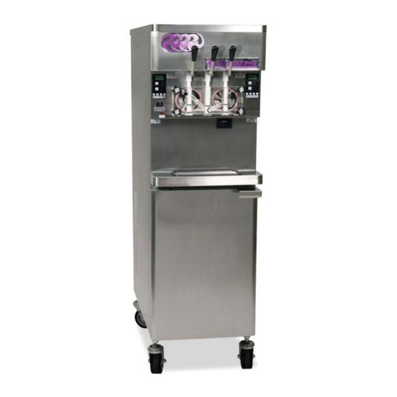
SECTION 1 DESCRIPTION AND SPECIFICATIONS 1.1 DESCRIPTION The Stoelting O431 fl oor model machine is pressure fed. The machine is equipped with fully automatic controls to provide a uniform product. The machine is designed to operate with almost any type of commercial soft-serve or non-dairy mixes available, including ice milk, ice cream, yogurt, and frozen dietary desserts. -
Page 10: Specifi Cations
Model O431 Dimensions Machine with crate width 19-1/8’’ (48,6 cm) 27’’ (68,6 cm) height 67-7/8’’ (172,4 cm) 78’’ (198,1 cm) depth 37-3/4’’ (95,9 cm) 48’’ (121,9 cm) 500 lbs (226,7 kg) 650 lbs (294,8 kg) Weight Electrical 1 Phase, 208-240 VAC, 60Hz Air Cooled Water Cooled running amps... -
Page 11: Modes Of Normal Operation
1.3 MODES OF NORMAL OPERATION Following are details of the operational modes on the O431. NOTE: The preset amounts, times, and temperatures listed below are references to actual settings on the IntelliTec control. Refer to Table 1-1 on page 6 for details on each setting. -
Page 12: Sleep 1 Mode
The “Standby Mode” maintains product quality during slow times, while minimizing reactivation time. This mode lasts for a preset time (Stb Time). Once this time has been reached without user interruption, the control moves into the “Sleep 1 Mode”. Refer to Figure 1-4 for a graphical representation of the “Standby Mode”. -
Page 13: Clean Mode
H. CLEAN MODE A. SERVE AND STANDBY MODE When the CLEAN button is pressed, freezing cylinder In the event of a temperature sensor failure on a freezing refrigeration stops, the drive motor starts and will run for cylinder, the IntelliTec control will function in two modes, 20 minutes, and a 5 minute countdown timer is displayed. - Page 14 IntelliTec Control Setting Specifi cations Basic Menu DISPLAY Value MODE DEFINITION CutOut Serve Amp draw setting for cut out Cut In T 21°F Serve Temperature setting for cut in Cycles Serve Freezing cycles before going into Standby Mode Stir On 15 sec Serve Stir-only on time...
-
Page 15: Installation Instructions
SECTION 2 INSTALLATION INSTRUCTIONS Install the four casters. Turn the threaded end 2.1 SAFETY PRECAUTIONS into the machine until no threads are showing. To Do not attempt to operate the machine until the safety level, turn out casters no more than 1/4” maximum, precautions and operating instructions in this manual are then tighten all jam nuts. -
Page 16: Mix Pump
6” (15cm) Figure 2-2 Mix Hose Installation Allow the remaining 6” (15cm) of tubing to feed 2.5 MIX PUMP through pump until the hose adapter prevents A. MIX PUMP HOSE INSTALLATION further feeding. Follow the steps below to install the mix pump hose in Turn the pump off. - Page 17 Figure 2-3 Mix Pump Connections for Standard Mix Container Connect the free end of the tubing to the mix check Slide the hose clip over free end of 3/8” (9,5mm) valve. Observe the direction of the check valve ID plastic food grade tubing. Attach the free end fl...
-
Page 18: Mix Low Level Indicator Adjustment
Repeat steps 1 to 3 for the middle port and for C. MIX LOW LEVEL INDICATOR ADJUSTMENT the right port of the mix inlet manifold. The sensitivity of the “Mix Low” indication that displays on Place three mix bags into the mix container. the control panel can be adjusted to operator preference. -
Page 19: Initial Set-Up And Operation
SECTION 3 INITIAL SET-UP AND OPERATION 3.1 OPERATOR’S SAFETY PRECAUTIONS 3.2 OPERATING CONTROLS AND INDICATORS SAFE OPERATION IS NO ACCIDENT; observe these Before operating the machine, it is required that the op- rules: erator know the function of each operating control. Refer to Figure 3-1 for the location of the operating controls on Know the machine. - Page 20 C. SPIGOT SWITCH J. DRIVE MOTOR OVERLOAD The spigot switch is mounted to the spigot cam assembly The internal drive motor overload will trip if the drive behind the header panel. When the spigot is opened to motor is overloaded. It will reset after approximately 10- dispense product, the spigot switch opens and the “Serve 12 minutes.
-
Page 21: Disassembly Of Machine Parts
3.3 DISASSEMBLY OF MACHINE PARTS WARNING Moving machinery can grab, mangle and dismem- ber. Place the Main Freezer Power Off/On switch in the OFF position before disassembling for cleaning or servicing. Before using the machine for the fi rst time, complete machine disassembly, cleaning and sanitizing proce- dures need to be followed. -
Page 22: Cleaning Disassembled Parts
3.4 CLEANING DISASSEMBLED PARTS 3.7 ASSEMBLING MACHINE Disassembled machine parts require complete cleaning, To assemble the machine parts, refer to the following steps: sanitizing and air drying before assembling. Local and state NOTICE health codes will dictate the procedure required. Some Petrol-Gel sanitary lubricant or equivalent must be state health codes require a four sink process (pre-wash, used when lubrication of machine parts is specifi... -
Page 23: Sanitizing
When sanitizing the machine, refer to local sanitary regu- lations for applicable codes and recommended sanitizing products and procedures. The frequency of sanitizing must comply with local health regulations. Mix sanitizer according to manufacturer’s instructions to provide a 100 parts per million strength solution. Mix sanitizer in quanti- ties of no less than 2 gallons of 90°F to 110°F (32°C to 43°C) water. -
Page 24: Initial Freeze Down And Operation
Using a sanitized soft bristle brush (or equivalent) Press the SET button. A cursor will start blinking dipped in sanitizing solution, clean the mix under the far right digit. container. Change the value to 8.0. Press the left arrow () After fi... -
Page 25: Serving Product
Press the SET button to save the value. The LCD Place the mix pump switch in the ON position. will read “CutOut Set -- OK”. Place a container under the spigot and open the Press the SEL button. The LCD will read “CutOut spigot to allow the mix to fl... -
Page 26: Operation Of Mix Pump
When checking the temperature, stir the thermometer in Air Operation: The air compressor operates the frozen product to get an accurate reading. whenever the peristaltic mix pump is running. Air enters through a check valve on the piston Old mix, or mix that has been stored at too high a tempera- downstroke. -
Page 27: Disassembly And Inspection Of Removable Parts
Completely disassemble the hose assembly and 3.14 DISASSEMBLY AND INSPECTION OF the check valve (Fig. 3-10). Place hoses, tee, REMOVABLE PARTS check valve assembly, and pickup hose adapter in Inspection of removable parts should be made whenever 90° to 110°F (32°C to 43°C) mild detergent water maintenance is performed or when the pump requires and wash thoroughly. -
Page 29: Maintenance And Adjustments
SECTION 4 MAINTENANCE AND ADJUSTMENTS MACHINE ADJUSTMENT LOCKING THE CONTROL PANEL This section is intended to provide maintenance personnel The IntelliTec control has a tamper proof mode to prevent with a general understanding of the machine adjustments. unauthorized use. When set, all buttons on the control It is recommended that any adjustments in this section panel are disabled. -
Page 30: Readings (Service Personnel Only)
IMPORTANT: ERROR CODE READINGS The following details are recorded under the ERRCODES Before making changes to any settings, record menu for each of the last 25 error codes received: the original values. If the setting changes do not achieve desired results, return settings to their Err1 (hours) original values. -
Page 31: Adjustments (Service Personnel Only)
RUN STATISTICS Cut In T (°F) In addition to dynamic readings and recorded error code After the consistency value has been determined, details, the IntelliTec control records rolling averages of the Cut In T value can be adjusted. The Cut In run statistics. -
Page 32: Overrun Adjustment
Off Time (sec) Cab Off Increasing this value will increase the time between If the Refriger value is set to Cabinet and the freezing cycles in “Standby Mode” and result in temperature sensor in the cabinet fails, this setting an increase of product temperature in the barrel. determines the time between refrigeration cycles. -
Page 33: Mix Pump Hose Reposition
Turn the mix pump switch to the OFF position. Disconnect power sources/circuit breakers. Remove the back panel from the machine. On the air compressor side of the pump, locate the long/slender piston rocking arm. The rocking arm downward travel is limited by a stationery cam. -
Page 34: Cab Temperature Adjustment
Connect the new mix pump hose to the pickup Press the left arrow button () three (3) times to hose adapter using the small clamp. navigate to the Storage menu. Feed one end of the mix pump hose into the Press the up arrow button () once to navigate pickup hose side (left) of the black cover. -
Page 35: Condenser Cleaning (Air-Cooled Machines)
The United States Department of Agriculture and the Food When the tension is properly adjusted, the belt and Drug Administration require that lubricants used in will depress the approximate width of the belt with food zones be certifi ed for this use. Use lubricants only in the pressure of a fi... -
Page 37: Refrigeration System
SECTION 5 REFRIGERATION SYSTEM 5.1 REFRIGERATION SYSTEM NOTE The O431 refrigeration system has two functions: For qualifi ed service personnel only. Anybody work- ing with refrigerants must be certifi ed as a Techni- Medium-Temperature - Maintaining product cian TYPE I as required by 40 CFR 82 Subpart F temperature in the cab unit. -
Page 38: Refrigerant Recovery
A. REFRIGERANT RECOVERY NOTE Disconnect the machine from electrical supply If evacuation is not completed after 20 minutes, before removing any panels for servicing. press the Push To Freeze button again. This will keep the solenoid valves open. Remove all panels. If the system will not maintain a standing vacuum Connect the recovery unit to the suction and test with the vacuum pump off (gauge increases... -
Page 39: Compressor
Connect an ohmmeter to the C and R terminals. 5.4 COMPRESSOR Resistance through the run winding should be The O431 has a scroll type compressor (Refer to Figure 1.01 ±10%. 5-2). This compressor type uses two spiral shaped scrolls Connect ohmmeter to terminals C and S. to compress gas. -
Page 40: Condenser
5.6 EVAPORATOR WARNING The O431 has two freezing cylinder evaporators and a cab evaporator. Hazardous voltage EVAPORATOR TESTING The Main Freezer Power switch must be placed in the OFF position when disassembling for servicing. The evaporator can be checked for leaks using the bubble The machine must be disconnected from electrical test or using a leak detector. -
Page 41: Check Valve
If the pressure reading is higher than expected, Tighten clamp to 20 in/lb using a torque wrench. check to see if there is an overcharge of refrigerant. Replace insulation to the TXV and surrounding If the pressure reading is lower than expected, lines. -
Page 42: Hot Gas Bypass
HIGH PRESSURE CUTOUT REMOVAL Remove the panels. Recover refrigerant charge per instructions in Section 5.2. Leave the suction and discharge ports open to prevent pressure buildup during removal. Unsweat the high pressure cutout from the discharge line. Disconnect the wires from the high pressure cutout. -
Page 43: Water Valve (Water Cooled Models Only)
Adjust the hot gas bypass valve to 18 psig ±1. Connect the machine to the electrical supply, start the refrigeration cycle, and read the pressure. Wait 2 minutes to ensure pressure remains stable. The proper gauge reading should be 225-235 psig. Hand-tighten seal cap to valve. -
Page 44: Solenoid
5.8 SOLENOID SOLENOID MAGNETIC COIL INSTALLATION To replace the magnetic coil, perform the following pro- Solenoid valves are installed on the liquid and suction lines cedures: of each freezing cylinder evaporator and on the liquid line of the cab evaporator (Refer to Figure 5-13). A solenoid Connect the two electrical wires to the magnetic valve has a magnetic coil that, when energized, lifts a coil. -
Page 45: Filter Drier
5.9 FILTER DRIER The fi lter drier must be replaced every time the refrigeration system is opened for service. A new fi lter drier improves operation of the entire refrigeration system by stopping the circulation of moisture and by removing harmful con- taminants (Refer to Figure 5-14). -
Page 47: Electrical And Mechanical Control Systems
SECTION 6 ELECTRICAL AND MECHANICAL CONTROL SYSTEMS NOTE The wiring diagram is available in Section 8. INTELLITEC CONTROLLER The IntelliTec control is Stoelting’s most advanced con- troller. It combines all of the best features of previous controllers with advanced sensing and troubleshooting capabilities. -
Page 48: Drive Motor
Place the Main Power OFF/ON and Freezing A. CONTACTOR TESTS Cylinder OFF/ON switches in the OFF position. The following tests will show if a contactor is working properly. Install the belt and tighten the tension bolt. Open header panel and visually check the Use a Burroughs Belt Tension Gauge to set the IntelliTec control board. -
Page 49: Capacitors
Remove a lead from one of the capacitor terminals. B. DRIVE MOTOR INSTALLATION Place the drive motor in position and install the Using insulated pliers, discharge the capacitor four mounting bolts. by connecting a 20KΩ 5W resistor across the terminals. Place the pulley and key on the motor shaft. -
Page 50: Condenser Fan Motor (Air-Cooled Only)
Remove the three bolts holding the gearbox to B. FAN MOTOR REPLACEMENT the barrel. Disconnect machine from electrical supply before Remove the two bolts holding the gearbox to removing any panels for servicing. the mounting bracket and remove the gearbox through the rear of the machine. -
Page 51: Switches
Remove the mix containers and sliding drawer The clicking sound should be within the fi rst 1/2” from the cab. of the spigot glide movement (Refer to Figure 6-8). If the switch does not close, an adjustment Disconnect the tubing from the mix transfer line may be necessary. -
Page 52: Pump Pressure Switch
The motor should cutout when the gauge reads SPIGOT SWITCH REPLACEMENT 24 psig ±1. Remove the header panel. Open the spigot and monitor the gauge. The motor Remove the dispense rate adjuster knob located should cutin when the gauge reads 21 psig ±1. below the header panel. -
Page 53: Temperature Control Sensor
REED SWITCH REPLACEMENT TEMPERATURE CONTROL SENSOR Place the Main Power OFF/ON switch and both The temperature control sensor is a thermistor used to Freezing Cylinder OFF/ON switches in the OFF sense the temperature of the suction line. As the suction position. -
Page 55: Troubleshooting Error Codes
SECTION 7 TROUBLESHOOTING in the machine’s mix container or from product 7.1 ERROR CODES breakdown. Another common cause results from When the machine experiences a problem, one of the a restriction preventing mix from entering the following error codes will be displayed on the control freezing cylinder. - Page 56 Error Code 5 - Freezing Cylinder Sensor Error Code 6 - Hopper Sensor (single hopper machines) The Freezing Cylinder Sensor Error (E5) indicates The Hopper Sensor Error (E6) will not occur on a failure of the barrel sensor or an extreme out of the O431 machine.
- Page 57 Error Code 11 - Low Temperature The Low Temperature Error (E11) occurs when the temperature of the gas refrigerant at the freezing cylinder sensor falls below -20°F. Although the machine will not shut down, the active freezing cycle will immediately end. This error usually occurs when the machine continues to run in a low mix condition or if the machine runs out of mix.
-
Page 58: Troubleshooting - Machine
7.3 TROUBLESHOOTING - MACHINE PROBLEM POSSIBLE CAUSE REMEDY 1 Power to machine is off. 1 Supply power to machine. 2 Freeze-up (auger will not turn). 2 Turn Clean/Off/On switch Off for 15 minutes, Machine does not then restart. run. 3 Front door not in place. 3 Assemble front door in place. -
Page 59: Troubleshooting - Mix Pump
7.4 TROUBLESHOOTING - MIX PUMP PROBLEM POSSIBLE CAUSE REMEDY 1. Power to pump is off. 1. Supply power to pump. 2. Low voltage. 2. Check for low voltage. 3. Mix pump hose jammed inside black 3. Disconnect pump from power source. Remove cover/clamp. - Page 60 PROBLEM POSSIBLE CAUSE REMEDY 1. Mix pump hose service life is 1. Reposition/replace mix pump hose. exceeded. 2. Out of mix. 2. Replenish mix supply. Overrun too high. 3. Overrun setting too high. 3. Decrease overrun setting. 4. Pick-up leg of mix pump hose is 4.
-
Page 61: Replacement Parts
SECTION 8 REPLACEMENT PARTS BRUSHES, DECALS AND LUBRICATION Part Description Quantity 208135 Brush - 4" X 8" X 16" (Barrel) 208380 Brush - 1/4" X 3" X 14" 208387 Brush - 1/2" X 5" X 24" 208465 Brush - 1" X 3-1/2" X 18" 208467 Brush - 3/8"... -
Page 62: Auger Shaft And Front Door
AUGER SHAFT AND FRONT DOOR Part Description Quantity 149003 Bushing - Front Auger Support 381804 Auger Flight 417006 Grid - Drip Tray (Metal) 482004 Knob - Air Bleed Valve 482019 Knob - Front Door 624520-5 O-Ring - Air Bleed Valve - Black (5 Pack) 624598-5 O-Ring - Outside Spigot - Black (5 Pack) 624614-5... -
Page 63: Cab Tubing Assembly
CAB TUBING ASSEMBLY Part Number Description Quantity 264235 Clamp - Metal (1/4" ID Tubing) 264241 Clamp - Metal (1/2" ID Tubing) 264243 Clamp - Metal (3/8" ID Tubing) 375819 Elbow - Barbed (3/8"- 1/4") 376041 Tee Connector - 3-Way (Stainless) 558114 Mix Container Only 624607-5... -
Page 64: Spigot Cam Assembly
SPIGOT CAM ASSEMBLY Part Number Description Quantity 428045 Knob - Spigot Handle (Black) 570961 Pin - Cotterless Clevis (Spigot Cam) 696044 Spring - Torsion (Spigot Cam) 718773 Switch - Spigot Cam 2158082 Glide - Spigot Socket 2158260 Handle - Spigot (Metal Only) STAINLESS STEEL PANELS Part Number Description... -
Page 65: Rear
REAR 598032 763181 762359 718794 152238 778027 598031 763017 558004 282062 284085 743654 357102 230654 Part Number Description Quantity 152237 Belt - Gripnotch (AX35) (Each) (50 Hz) 152238 Belt - Gripnotch (AX34) (Each) (60 Hz) 230654 Capacitor (Fan Motor) 282062 Compressor - 1 PH - 60 Hz (Scroll) (No Capacitors) 282076 Compressor - 1 PH - 50 Hz (No Capacitors) -
Page 66: Right
RIGHT 718539 614233 2187264 302042 272065 763423 522858-SV 762275 Part Number Description Quantity 231078 Capacitor - Run (#522858 Motor) 231095 Capacitor - Start (#522858 Motor) 272065 Valve Coil - Solenoid (#763423 Valve) 302042 Cord - Power 368325 Filter - Air (Condenser) 522858-SV Motor - Drive (60 Hz) 522859... -
Page 67: Left
LEFT 762481 763422 763482 762457-SV 342008 458010 Part Number Description Quantity 342008 Drier (Liquid Line) 458010 Indicator - Liquid Line 493042 Flasher - Indicator Light (Cab On - Off) 762481 Valve - Expansion (Has 2) 762457-SV Valve - Expansion (w/Orifi ce) (Cab) 763422 Valve - Solenoid (1/4") (Liquid Line) (Has 3) 763482... -
Page 68: Front Panel And Header Panel
8.10 FRONT PANEL AND HEADER PANEL 521686-230 295017 332541 718532 719025-SV 718895 202235 493041 718532 744276 Header Panel - Back 744142 230638 618180 295017 230653 Part Number Description Quantity 202235 Circuit Breaker 230638 Capacitor - Start (#282062 Compressor) 230653 Capacitor - Run (#282062 Compressor) 231048... -
Page 69: Cab Interior
8.11 CAB INTERIOR 522307-SV 162048 128311 2187296 128312 396449 3177231 719123-SV 4183338 736084 284095 672724 2187306 Part Number Description Quantity 128311 Hinge - Door (Top & Bottom) (Cab) 128312 Mix Container Holder Assembly w/Rollers (Cab) 162048 Blade - Fan (Evaporator) (Cab) 266018 Clip - “J”... -
Page 70: Pump Parts
8.12 PUMP PARTS Part Number Description Quantity 128295 Rocker Arm Assembly w/Screw 369037 Fitting - Flared Brass - Air Inlet 376035 Tee Connector - Air Pressure Switch 432003-SV Valve Head Only w/Tubes 522229 Motor - Pump 538306 Nut - Motor Mounting 644065 Screw - Rocker Arm 650146... - Page 71 8.12 PUMP PARTS (CONTINUED) 1177037 1177034 1171864 1171862 1171958 1171863 1171860 1177035 1171861-SV 1177036 1171866 1171986 369037 762246 1171987 717928 432003-SV 644065 653042 128295 376035 1171868 1171874 1171985 1171867 1171988 1171870 1177681 1171986 1171981 3171952 1171984 1171983 2177812 1171955 1171866 1171982 1171979 1171980...
-
Page 72: Part Kits
8.13 PART KITS Part Number Description Quantity 1177436 Air Compressor Kit (Reed Valve, Piston & Cylinder Sleeve) (Cab) 128296 Piston & Cylinder Sleeve 1171860 Valve Spring 1171861-SV Needle Valve w/O-Ring 1171863 Valve Guide 1171864 O-Ring 1183624 O-Ring & Bearing Kit 149003 Bushing - Front Auger Support 624520... -
Page 73: Refrigeration Diagram And Wiring Diagram
8.14 REFRIGERATION DIAGRAM AND WIRING DIAGRAM... - Page 75 DOMESTIC WARRANTY (Including Mexico) SOFT SERVE / SHAKE EQUIPMENT 1. Scope: PW Stoelting, L.L.C. (“Stoelting”) warrants to the first user (the “Buyer”) that the freezing cylinders, hoppers, compressors, drive motors, speed reducers, and augers of Stoelting soft serve / shake equipment will be free from defects in materials and workmanship under normal use and proper maintenance appearing within five (5) years, and that all other components of such equipment manufactured by Stoelting will be free from defects in material and workmanship under normal use...
Need help?
Do you have a question about the Stoelting O431 and is the answer not in the manual?
Questions and answers