Advertisement
General Information
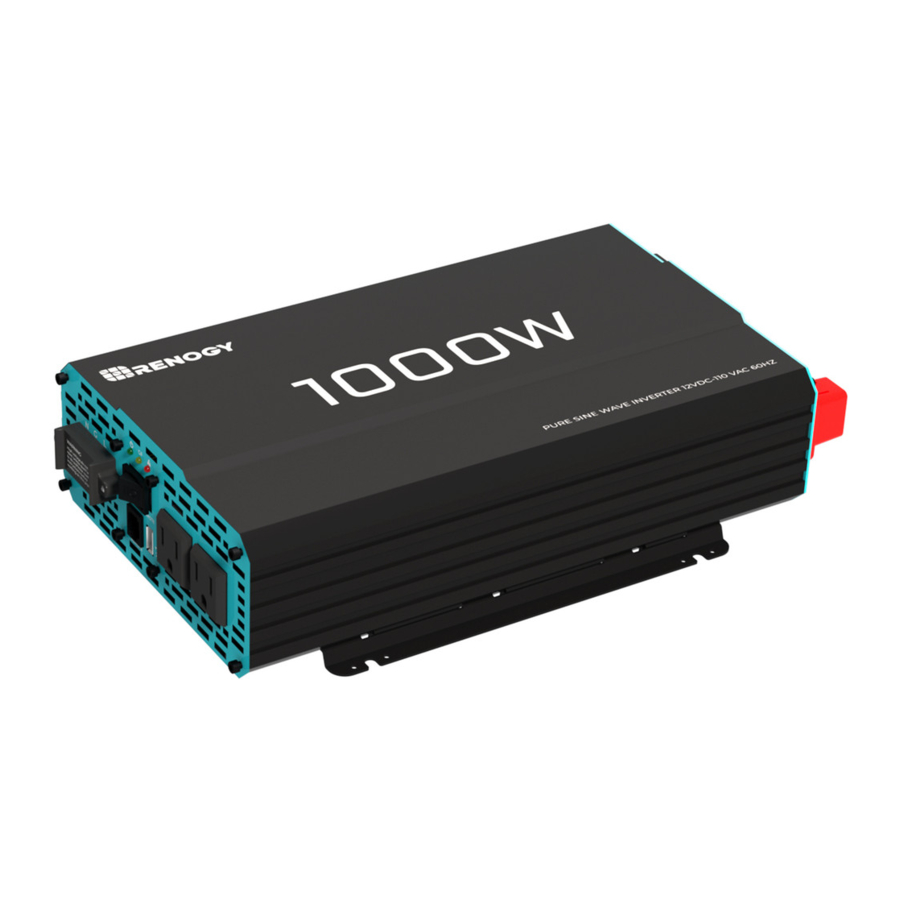
The Renogy Pure Sine Wave Power Inverter delivers superior performance for remote off-grid applications, capable of producing cleaner, smoother, and more reliable electricity for a user's electronic needs.
Key Features
- Robust and sleek design
- Optimized for 12 VDC system voltage
- Clean power for safe operation of sensitive electronics
- Easy-to-read LED indicator display
- Multiple protection features (LVD, HVD, AC Overload and Over Temperature)
- Excellent Surge Rating: 2x the Power Rating
- Ground-fault circuit interrupter(GFCI) protection
- Build-in 5V/2.1A USB port
Pure Sine Wave
The Renogy Power Inverters output a pure sine wave similar to the waveform of the grid power. In a pure sine wave, the voltage rises and falls in a smooth fashion with very low harmonic distortion and cleaner utility-like power.

This gives users stable enough power to operate tools, fans, lights, computers, and other electronics without any interference. Pure sine wave inverters are in many cases more efficient, allowing users to use less energy and allow for more device capability. The main advantage to pure sine wave inverters is that they are used to operate sensitive electronic devices that require a high quality waveform with little harmonic distortion. Almost any electronic device could be powered using a pure sine wave inverter.
Included Components
The Renogy Pure Sine Wave Battery Inverters will be shipped wi th inverter cables and a space for powering the inverter on or off.
| Inverter Model | Gauge |
| 700W | 6 AWG 3ft |
| 1000W | 4 AWG 3ft |
| 2000W | 4 AWG*2 3ft |
| 3000W | Does not include |
Wired remote control

| List dimensions | 2.875 x 2.3125 x 0.9375in, 73 x 58.7 x 23.8mm |
| Thickness | 0625in, 1.5mm |
| Wire length | Approx 19.8ft |
Identification of Parts
AC Side

Key Parts
- High Output AC Terminals (30A) — These terminals are for connecting 115V AC devices that require more than 15 amps to operate or for connection to distributed wiring that has multiple AC outlets. Remove the two screws on protective cover to access the terminals. Any AC output wiring that is directly connected must comply with US National Electric Code (NEC) wiring gauge recommendations.
![]()
The spacing distance between the LNG is 8mm.- Facing the front panel, the terminals are:
NEUTRAL and GROUND are bonded inside the inverter to comply with the National Electric Code (NEC) requirement that any AC source must have a neutral to ground connection.LEFT Middle Right Neutral (N) Ground(G) Live(L)
- Facing the front panel, the terminals are:
- Power LED (Green) — When this green LED is lit, the inverter is operating.
- GFCI LED (Yellow) — When the yellow LED is lit, the ground fault circuit has been interrupted. Shut down the inverter and restart.
- Fault LED (Red) — The red indicator turns on as the inverter shuts down due to overheating, overload, under voltage, or over voltage.
- Immediately turn off all AC appliances if the Fault LED is lit. Allow the inverter to cool before continuing. Make sure that the ventilation vents are not blocked.
- If an inverter shutdown was preceded by a buzzing sound, there may be an excessive load in combination with low voltage or a cable problem.
- ON/OFF Switch — Controls AC output.
- AC Outlets (15A) — 115V AC 60Hz, up to 15amps for 2000W and 3000W models, up to 6.1 amps for 700W,up to 8.7 amps for 1000W.
- USB Power Port — 5 volts/2.1A for charging tablets, smartphones, and other small electronic devices.
- Remote Switch Connection — Insert wired remote switch to the connection port. Set ON/OFF switch to "remote" position.

Alarm —If there is a buzzing sound, the battery is low. The user should reduce the AC load, charge the battery, and check the DC cable for excessive losses.
DC Side

You are advised to select a wire diameter corresponding to a copper nose that is less than or equal to 4mm.
KEY PARTS
- Positive Terminal — Positive (+) DC Input (Red)
- Cooling Fans — Thermally controlled
- Negative Terminal — Negative (−) DC Input (Black)
- Ground Terminal — For insulated safety ground wire.
Installation

Make sure inverter is in the off position before connecting anything.

Do not over-torque or over tighten the terminals. This could potentially damage the unit.
Refer to the technical specifications for max wire sizes on the controller and for the maximum amperage going through wires.
Location Recommendations
Never install the inverter in a sealed enclosure with flooded batteries. Gas can accumulate and there is a risk of explosion.
Ensure installation follows the following guidelines:
- Cool, dry, well-ventilated area — Heat is the worst enemy for electronic equipment. Inverters must be in an area where the fans are not blocked or where they are not hit directly by the sun. They should be in an area free of any kind of moisture and allow for clearance of at least 10" around the unit to provide for adequate ventilation.
- Protection against fire hazard — the unit should be away from any flammable material, liquids, or any other combustible material. The unit can spark and the consequences could be severe.
- Close proximity to battery bank — prevent excessive voltage drop by keeping the unit close to the battery bank and having a properly sized wire going from the battery bank to the inverter.
![]()
Do not install the inverter in the same compartment as the battery bank because it could serve as a potential fire hazard.- Limiting electromagnetic interference (EMI) — ensure the inverter is firmly grounded to a building, vehicle, or earth grounded. Keep the inverter away from EMI receptors such as TVs, radios, and other audio/visual electronics to prevent damage/interference to the equipment.
- Secure inverter — the inverter could be stand alone or mounted using the outlying terminals on the inverter.
The inverter should never be mounted vertically on a vertical surface since it would present a hazard for the fan opening which is crucial for cooling the inverter.
Sizing a Battery Bank
- Determine the amount of Watts (Amps * Volts) for the load, and how long the load needs to operate — each electrical appliance has technical specifications indicating the watts, or the volts and amps required for operation.
- Estimate load run-time — Battery size depends on load watts and run-time. Most loads are not constant, so estimation is very important.
- Utilize the formula Watts = Volts * Amps
- Determine Amps used for how many hours – Amp-hour (Ah)
For this Renogy inverter, the battery bank will be 12 volts direct current (12 VDC)
| Example | |
| A Microwave oven = 700 Watts 12V battery bank | 700 Watts to run microwave oven using the batteries as if it was a 12VDC microwave requires 58 Amps 700 Watts/12 Volts = 58 Amps |
| Load Operation = 3 hours | Now that amps have been determined, the amp-hours need to be determined. The microwave will be used for approximately 3 hours a day. 58 Amps * 3 hours = 174 Ah |
| At least a 174 Ah battery must be selected in order to use the 700-Watt microwave at 3 hours a day. However, determining a battery size is also dependent on the battery that is able to handle repeated discharge/charge cycles. | |
This is just an example. Actual quantities vary by battery capacity and rates of discharge.
To power the microwave in the example, the user must use an inverter that is at least 1000 watts, if not more.
Grounding
If available, the chassis ground lug should be connected to a ground point such as a vehicle chassis or boat grounding system. In fixed locations, connect the ground lug to earth ground. The connections to ground must be tight and against bare metal. Grounding is highly recommended for both when using the inverter in a mobile application, such as an RV, or in a building.
Recommended wire material: insulated copper strand wire
Recommended wire size:
- 14AWG to 18AWG (700W)
- 14AWG (1000W)
- 12AWG (2000W)
- 10AWG (3000W)
DC Side Connection
The Renogy Pure Sine Wave Inverters are suitable for 12V battery bank systems ONLY. Not following the minimum DC requirement will cause irreversible damage to the unit.
Be careful of the positive and negative poles. Reversing the poles might cause permanent damage to the inverter. It will surely blow the internal fuse.
Damage to the Renogy inverters due to reverse polarity is NOT covered by warranty.
The input terminals of the inverters have large capacitors connected to them. Once a positive and negative wire are connected to the terminals, it will complete the circuit, and commence drawing a heavy current momentarily. As a result, there may be a sparking occurring even if the inverter is in the off position. To minimize sparking, it is recommended that the user have the appropriate size wire feeding into the inverters and/or install an external fuse leading into the inverter.

- Flip inverter power to OFF position (on AC side)
- Remove Cap, then unscrew inverter terminals and connect battery connections. Then tighten.
For your safety, it is recommended to use a battery fuse.
| Model | RNG-INVT-70012V-P2 | RNG-INVT-100012V-P2 | RNG-INVT-200012V-P2 | RNG-INVT-300012V-P2 |
 Continuous Output Power Continuous Output Power | 700 W | 1000 W | 2000 W | 3000 W |
| Battery Fuse | 100 A | 150 A | 250 A | 400 A |
Operation
Assuming proper battery connection, the inverter is now ready for use.
AC Side Operation

- Connect electronic devices to electrical socket (s) on inverter. Flip inverter power to ON position (on AC side)
- When finished, switch AC devices off FIRST, then turn off inverter switch
Avoid switching on the inverter with the load (electronic devices) already switched on. This may trigger an overload since some electronic devices have an initial high power surge to start.
When switching off the inverter, turn off the electronic devices first. Although the inverter is off, the capacitors will still have a charge, so the DC and AC terminals must be disconnected if altering the circuitry.
Recommended Ground-Fault Circuit Interrupter (GFCI)
A ground-fault circuit interrupter, or GFCI, is a device that help protect people from electric shocks by de-energizing a circuit or portion of a circuit within an established period of time when a current to ground exceeds some predetermined value that is less than that required to operate the overcurrent device (circuit breaker or fuse) of the supply circuit. GFCIs are usually required in wet or damp locations.
While the inverter is equipped with a GFCI, it is recommended to install an external GFCI where you can manually test the circuit.
The following table lists GFCIs that meet the specifications and will function properly when they are connected to the AC Outlets of the inverter.
| Tested GFCI M odels | |
| Manufacturer | Model Number |
| Leviton | GFNT2 |
| Hubbell | GFP1305 |
| Hubbell | GF15WLA |

Risk of electrical shock. Use only ground-fault circuit inter rupters [receptacle (s) or circuit breaker(s)] compatible with your P2 inverter.
Risk of electric shock. Use only class A ground-fault circuit-interrupter [receptacle (s) or circuit breaker(s)]. Other types may fail to operate properly when connected to this unit.
GFCIs shall be installed in a recreational vehicle's wiring system to protect all branch circuits.

Inverter Troubleshooting
| Indicator | Potential Issue | Troubleshoot |
| Alarm beeps | Input voltage is below 10.5V | Keep input voltage above 10.5V |
| Input voltage is above 16.0V | Keep input voltage below 16.0V | |
| Fault LED Lit, inverter shut down and alarm on | Input voltage is below 10V | Keep input voltage above 10V |
| Input voltage is above 16.5V | Keep input voltage below 16.5V | |
| Inverter overheats | Allow inverter to cool down | |
| Check for adequate ventilation | ||
| Reduce the load on inverter | ||
| Operating equipment draws too much power | Use a higher wattage inverter or use a lower powered device | |
| Inverter is short circuited | Disconnect the inverter and turn off the ON/OFF switch to reset | |
| Yellow LED Lit - Inverter shut down | GFCI tripped | Disconnect appliances and turn off the ON/OFF switch to reset |
External Fusing
Fusing is a recommended in PV systems to provide a safety measure for connections going from panel to controller and controller to battery. Remember to always use the recommended wire gauge size based on the PV system and the controller.
| NEC Maximum Current for different Copper Wire Sizes | |||||||||
| #AWG | 16 | 14 | 12 | 10 | 8 | 6 | 4 | 2 | 0 |
| Max. Current | 10A | 15A | 20A | 30A | 55A | 75A | 95A | 130A | 170A |
Specifications
| Model | RNG-INVT-70012V-P2 | RNG-INVT-100012V-P2 | RNG-INVT-200012V-P2 | RNG-INVT-300012V-P2 |
| Continuous Power | 700 W | 1000 W | 2000 W | 3000 W |
| Input Voltage | 12V DC | |||
| Output Voltage | 115V AC | |||
| Peak surge | 1400 W | 2000 W | 4000 W | 6000 W |
| Efficiency | > 90% | |||
| Frequency | 60Hz | |||
| Total harmonic distortion (THD) | < 3% | |||
| No load current draw | < 0.8A | < 1.0A | < 2.0A | < 2.5A |
| Battery low alarm | 10.5V ± 0.5V DC | |||
| Battery low shutdown | 10.0V ± 0.5V DC | |||
| Over voltage shutdown | 16.5V ± 0.5V DC | |||
| Cooling fan | Thermally controlled | |||
| AC output sockets | 2 | 2 | 3 | 3 |
| USB power port | 5V/2.1A | |||
| Power output control | AC On/Off Switch | |||
| Dimensions | 12.2×7.4×3.3 in | 12.9×6.8×3.3 in | 17.8×8.6×4 in | 18.9×9×4 in |
| Net weight (approximate) | 5.6 lb | 6.0 lb | 11.7 lb | 12.5 lb |
| Certification | ETL Listed to UL 458 and CSA 22.2 NO 107.1-01 | |||
| Wired remote control | ||||
| List dimensions | 2.875 x 2.3125 x 0.9375in, 73 x 58.7 x 23.8mm | |||
| Thickness | 0625in, 1.5mm | |||
| Wire length | Approx 19.8ft | |||
Dimensions

Important Safety Instructions
This manual contains important safety, installation, and operating instructions for the inverter. The following symbols are used throughout the manual:
Indicates a potentially dangerous condition. Use extreme caution when performing this task.
Indicates a critical procedure for safe and proper operation of the inverter.

Indicates a procedure or function that is important to the safe and proper operation of the inverter.
General Safety Information
- Installation and wiring must comply with the Local and National Electric Codes (NEC) and must be done by a certified technician.
- Read all of the instructions and cautions in the manual before beginning the installation.
- There are no serviceable parts for this inverter. Do NOT disassemble or attempt to repair the inverter.
- Make sure all connections going into and from the inverter are tight. There may be sparks when making connections, therefore, make sure there are not flammable materials or gases near installation.
Inverter Safety
- The inverters are suitable for 12V Battery Banks ONLY.
- ALWAYS make sure inverter is in OFF position and disconnect all AC and DC connecting when working on any circuit associated with the inverter.
- NEVER connect the AC output of the unit directly to an Electrical Breaker Panel/ Load Centre which is also fed from the utility power/generator.
- When connecting battery terminals, ensure the polarity of the battery connections is correct. Incorrect polarity may cause permanent damage to the unit.
- Be careful when touching bare terminals of capacitors as they may retain high lethal voltages even after power is removed.
Battery Safety
- Do NOT let the positive (+) and negative (-) terminals of the battery touch each other.
- Use only sealed lead-acid, flooded, lithium battery, or gel batteries which must be deep cycle.
- Explosive battery gases may be present while charging. Be certain there is enough ventilation to release the gases.
- Be careful when working with large lead acid batteries. Wear eye protection and have fresh water available in case there is contact with the battery acid.
- Over-charging and excessive gas precipitation may damage the battery plates and activate material shedding on them. Too high of an equalizing charge or too long of one may cause damage. Please carefully review the specific requirements of the battery used in the system.
Installation Safety
- The unit should be installed in a well-ventilated, cool, and dry environment. Make sure the fans of the unit and the ventilation holes are not blocked.
- Do not expose the unit to rain, moisture, snow, or liquids of any type.
Renogy reserves the right to change the contents of this manual without notice.
US
2775 E Philadelphia St, Ontario, CA 91761, USA
909-287-7111
www.renogy.com
CN
苏州高新区科技城培源路1号5号楼-4
400-6636-695
https://www.renogy.cn
JP
https://www.renogy.jp
CA
https://ca.renogy.com
AU
https://au.renogy.com
UK
https://uk.renogy.com
DE
https://de.renogy.com
Documents / Resources
References
![www.renogy.com]() Renogy® Official- offer all off grid solar system products
Renogy® Official- offer all off grid solar system productsRENOGY如果新能源 | 让每个人拥有独立清洁的能源
![ca.renogy.com]() Renogy® Canada solar off-grid items, Canadian solar panels
Renogy® Canada solar off-grid items, Canadian solar panels![au.renogy.com]() Solar Power Kits & Equipment for Sale | Renogy Australia
Solar Power Kits & Equipment for Sale | Renogy Australia![uk.renogy.com]() Top off-grid solar kits, lithium batteries supplies | Renogy UK
Top off-grid solar kits, lithium batteries supplies | Renogy UK![de.renogy.com]() Renogy bietet alle Produkte für netzunabhängige Solarsysteme anRenogy DE
Renogy bietet alle Produkte für netzunabhängige Solarsysteme anRenogy DE
Download manual
Here you can download full pdf version of manual, it may contain additional safety instructions, warranty information, FCC rules, etc.
Download Renogy 700w, 1000w, 2000w, 3000w - Power inverter Manual
Advertisement


Need help?
Do you have a question about the 700w and is the answer not in the manual?
Questions and answers