
Related Manuals for Spectrum Digital AppBox C21


Summary of Contents for Spectrum Digital AppBox C21
- Page 1 AppBox C21 System User’s Guide Specializes in designing with Microchip products AppBox C21 System User’s Guide AppBox...
- Page 2 Notice ! Spectrum Digital, Inc (SDI) provides the enclosed product under the following conditions: The user/customer assumes ALL responsibility and liability for the proper use, storage, and safe handling of the product. Further, the user indemnifies SDI from all claims arising from the use, installation, storage, and handling of the product.
-
Page 3: Table Of Contents
........Attachment of the Distribution Box to the AppBox C21 . -
Page 4: Introduction
1.0 Introduction This document describes the features of the AppBox C21. The AppBox C21 is designed to be used in an industrial environment with a CAN, RS-485, or LIN interface and provide flexible, modular I/O (AppIO) for specific applications. These AppIO Modules allow customized solutions to be integrated for a wide variety of applications that need to go into a CAN, RS-485, or LIN communications environment. -
Page 5: Appbox C21 Applications
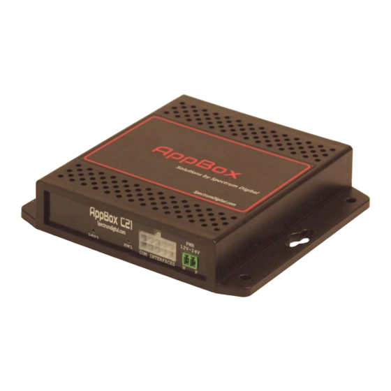
Software code generation suite) can be obtained from Microchip/Atmel at: https://www.microchip.com/development-tools/. 1.4 AppBox C21 Front Panel The features of the front panel on the AppBox C21 are shown in the figure below: LED1 AppBox C21 Front Panel 1.5 AppBox C21 Accessories... -
Page 6: Appbox C21 Communication Expansion
Distribution Box (Part/SKU #: 703924-0001) and AppBox cable (Part/SKU #:703923-0001) are required. The Distribution Box expands the J2 connector to four (4) images of the AppBox C21 J2 connector. The AppBox cable bridges all signals on the AppBox C21 J2 connector to a connector on the Distribution Box. -
Page 7: Installation
2.1 Attaching Power to the AppBox C21 Power can be provided to the AppBox C21 by two different means; the AppBox power supply with cable (Part/SKU #: 703925-0001), or wiring the 2 position terminal block header (included with AppBox C21) that plugs into the C21 CPU Board’s power input connector. -
Page 8: Installation Of Appio Modules
+12 -24 VDC is present. Place the meter/scope probes on the 2 screws to measure. 11. Turn off the power source 12. Insert the terminal block header into the power input of the AppBox C21. 13. Turn on the power source. -
Page 9: Attachment Of The Distribution Box To The Appbox C21
16. Apply power to the AppBox C21 2.3 Attachment of Distribution Box to the AppBox C21 Listed below are the steps to attach the Distribution Box (Part/SKU #: 703924-0001) to the AppBox C21: 1. Remove ALL power to the AppBox C21 enclosure 2. -
Page 10: Installation Of Atmel-Ice
6. Plug the emulator end of the ribbon cable into the “SAM” Port on the emulator 7. Plug in the Atmel-ICE debug into connector J6 on the AppBox C21 CPU board. Visually inspect the connection to insure all the board pins are in the female cable connector. -
Page 11: Interfaces
3.0 Interfaces This section describes the interfaces on the AppBox C21 CPU Board. These interfaces include the connectors, jumpers, switches, LEDs, and test points. The location of each of these interfaces is shown in the figure below: EXT1 LED1 EXT2... -
Page 12: Connectors
The table below lists all the interfaces on the AppBox C21 CPU Board. AppBox C21 CPU BOARD INTERFACES INTERFACE NAME TYPE OF INTERFACE Connector for power input Connector for RS485/CAN/LIN Connector for header 5x2 Cortex-M Debug EXT1 Connector to AppIO Module... -
Page 13: J1, Power Connector
Pin 1, DGND Pin 2, VIN J1, Power Connector (card edge view) The following table shows the signals present on the J1 connector. J1, Power Connector Pin number Signal name DGND VIN, (+12-24 VDC) AppBox C21 System User’s Guide AppBox... -
Page 14: J2, Rs485/Can/Lin Connector
3.1.3 J6, Cortex-M Debug Connector The following table shows the signals on the J6 connector. J6, Cortex-M Debug Connector Pin number Signal name VDD_3V3, +3.3 volts PA31_SWDIO DGND PA30_SWCLK/TCK DGND No Connect No Connect No Connect DGND RESETn AppBox C21 System User’s Guide AppBox... -
Page 15: Appio Module Connectors
0.1 inch (2.54 mm) centers. Note: The user should be aware that several signals from the AppBox C21 CPU are shared and present on all 3 connectors. If the signals are used by one connector (AppIO Module) they should not be used on the other connectors. -
Page 16: Ext1, Appio Module 1 Connector
Master in slave out line of serial PA16_SPI_MISO peripheral interface, always implemented, bus type Clock for serial peripheral PA19_SPI_SCK interface, always implemented, bus type DGND Ground Ground VDD_3V3 Power for the AppIO Module Power for the AppIO Module AppBox C21 System User’s Guide AppBox... -
Page 17: Ext2, Appio Module 2 Connector
Master in slave out line of PB02_SPI_MISO serial peripheral interface, always implemented, bus type Clock for serial peripheral PB01_SPI_SCK interface, always implemented, bus type DGND Ground Ground Power for the AppIO VDD_3V3 Power for the AppIO Module Module AppBox C21 System User’s Guide AppBox... -
Page 18: Ext3, Appio Module 3 Connector
Master in slave out line of serial PB02_SPI_MISO peripheral interface, always implemented, bus type Clock for serial peripheral PB01_SPI_SCK interface, always implemented, bus type DGND Ground Ground Power for the AppIO VDD_3V3 Power for the AppIO Module Module AppBox C21 System User’s Guide AppBox... -
Page 19: Jumpers
3.2 Jumpers This section describes the jumpers on the AppBox C21 CPU board. All jumpers are located on the bottom side of the circuit board. All jumpers are surface mount jumpers. The figure below shows the location of each jumper. - Page 20 The table below describes the jumpers on the AppBox C21 CPU Board. JUMPER FACTORY SHIPPED POSITION DESCRIPTION NAME POSITION Installed = +5 V power to pin 1, EXT1 Installed Installed = +5 V power to pin 1, EXT2 Installed Installed = +5 V power to pin 1, EXT3...
-
Page 21: Switches
3.3 Switches The table below describes the switches on the AppBox C21 CPU board. TYPE OF FACTORY DEFAULT SWITCH NAME FUNCTION SWITCH POSITION Pushbutton PA28_IRQ/GPIO Open switch Connects RS485_A to SW2, position 1, on Rocker switch RS485_B RS485 terminator on... -
Page 22: Leds
3.5 Test Points This section discusses the test points on the AppBox C21 CPU Board. All test points are on the top side of the circuit board. Their location is shown in the diagram in section 3.0. The table below describes the test points on the AppBox C21 CPU board. -
Page 23: Mechanical Information
5.0 Mechanical Information The following drawing provides the mechanical information for the AppBox C21. All dimensions are in inches. Note: Drawing is NOT to scale. Top View AppBox C21 Side View AppBox C21 6.0 Schematics The following pages include the schematics for the AppBox C21 CPU Board inside the AppBox C21. - Page 26 100K 1% 10K 1% 10K 1% 10K 1% 4.7K 1% 4.7K 1%...
- Page 31 Spectrum Digital, Inc PO Box 1559 Sugar Land, TX. 77487-1559 Web site: www.spectrumdigital.com Sales: sales@spectrumdigital.com Support: support@spectrumdigital.com Copyright Spectrum Digital Inc, © 2020 519098-4001 AppBox C21 System User’s Guide AppBox...
Need help?
Do you have a question about the AppBox C21 and is the answer not in the manual?
Questions and answers