Table of Contents
Advertisement
Advertisement
Table of Contents

Related Manuals for Spectrum Digital XDS510PP


Summary of Contents for Spectrum Digital XDS510PP
- Page 1 XDS510PP MPSD Emulator Pod Installation Guide 1997 DSP Development Systems...
- Page 2 XDS510PP MPSD Emulator Pod Installation Guide 502222-0001 Rev. C April 1997 SPECTRUM DIGITAL, INC. 10853 Rockley Road Houston, TX. 77099 Tel: 281/561-6952 Fax: 281/561-6037 sales@spectrumdigital.com www.spectrumdigital.com...
- Page 3 IMPORTANT NOTICE Spectrum Digital, Inc. reserves the right to make changes to its products or to discontinue any product or service without notice, and advises its customers to obtain the latest version of relevant information to verify, before placing orders, that the information being relied on is current.
-
Page 4: Table Of Contents
Step 2: Connecting the Emulator to Your Target System ......Setting up the “XDS510PP.INI” file ........ -
Page 5: What You'll Need
Installing the XDS510PP MPSD Emulator Pod This chapter helps you install the XDS510PP MPSD emulator pod on a PC running Windows or Windows 95. When you complete the installation, refer to the appropriate C Source Debugger User’s Guide for software installation. -
Page 6: Hardware Checklist
Spectrum Digital, Inc What You’ll Need The following checklists detail items that are shipped with the XDS510PP MPSD emulator and additional items you’ll need to use these tools. Hardware checklist __ host An IBM PC/AT or compatible ISA/EISA-based PC with a hard- disk system and a 1.44M floppy-disk drive... -
Page 7: Preparing The Emulator For Installation
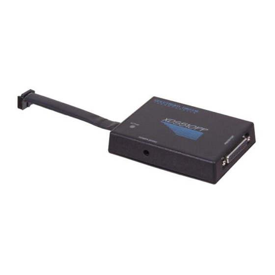
XDS510PP emulator pod. The XDS510PP is also known as a scan path adapter. The XDS510PP can be powered from two different sources. The easiest is to use power from the target system. This is done automatically when the target cable is connected. - Page 8 Spectrum Digital, Inc 1.3 Step 2: Connecting the XDS510PP to Your Target System Figure 1-1 shows how you connect the XDS510PP emulator pod and 25 conductor cable to your target system. In most cases, the target system will be a target board of your own design.
-
Page 9: Setting Up The Xds510Pp.ini File
Spectrum Digital, Inc Setting up the XDS510PP.INI file The xds510pp.ini file is used to set driver parameters. The “.INI” should be located in the same directory as the HLL Debugger. The D_DIR environment variable is used to select the Debugger directory. If the xds510pp.ini file doesn’t exist or can’t be found certain parameters are used as default. -
Page 10: Resetting The Emulator
TCK_RET signal. When alternate timing is selected TDI and TMS are changed to the rising edge of the clock. The default mode is to use the default timing. example: timing = alternate As shipped from the factory the xds510pp.ini file has the parameters set as: speed = 25 mode = epp... -
Page 11: Specifications For Your Target System's Connection To The Emulator
Chapter 2 Specifications for Your Target System’s Connection to the Emulator This chapter contains information about connecting your target system to the emulator. Your target system must use a special 12-pin connector for proper communication with the emulator. Topic Page Designing Your Target System’s Emulator Connector (12-pin Header) Emulator Cable Pod Logic... - Page 12 Emulation Pin 2 EMU3 Emulation Pin 3 ‘C3x H3 Presence detect. Indicates that the emulation cable is connected and that the target is powered up. PD should be tied to +5 volts in the target system. XDS510PP MPSD Emulator Pod Installation Guide...
- Page 13 Spectrum Digital, Inc Although you can use other headers, recommended parts include: straight header, unshrouded DuPont Connector Systems part # 65610-112 part # 65611-112 part # 37996-112 part # 67997-112 2.2 Emulator Cable Pod Logic Figure 2-2 shows a portion of the logic in the EMU320C3x emulator pod. Please note the 33 ohm resistors have been added to the EMU0, EMU1, and EMU2 lines.
- Page 14 The timing parameters are calculated from standard data sheet parts used in the emulator and cable pod. These parameters are for reference only. Spectrum Digital does not test or guarantee these timings. Figure 2-3. Emulator POD Timing...
- Page 15 Spectrum Digital, Inc Buffering Signals Between the Emulator and the Target System It is extremely important to provide high-quality signals between the emulator and the ‘C3x on the target system. In many cases, the signal must be buffered to produce a high-quality signal.
- Page 16 --EMU0, EMU1, EMU2, EMU3, and H3 -- are buffered through the same package. 6 to 12 inches TMS320C3x Emulator Header EMU0 EMU0 EMU1 EMU1 EMU2 EMU2 EMU3 EMU3 H3 Buffer Restrictions Don’t connect any devices between the buffered H3 output and the header ! XDS510PP MPSD Emulator Pod Installation Guide...
-
Page 17: Mechanical Dimensions For The 12-Pin Emulator Connector
(page 2-8) show the mechanical dimensions for the XDS510PP Scan Path Adapter and short cable. Note that the pin-to-pin spacing on the connector is 0.100 inches in both the X and Y planes. The XDS510PP enclosure is nonconductive plastic with four recessed metal screws. - Page 18 0.225 (Connector, Side View) Cable 0.420 0.100 key, pin #8 Cable (Connector, Front view) 0.70 0.100 stripe pins 2,4,6,8,10,12 pins 1,3,5,7,9,11 Note: All dimensions are in inches and are nominal dimensions, unless otherwise specified. XDS510PP MPSD Emulator Pod Installation Guide...
- Page 19 Index assembler 1-3 D_DIR environment variable 1-7, 1-8 autoexec.bat file 1-6 to 1-9 D_OPTIONS environment variable 1-7, 1-9 invoking 1-7 D_SRC environment variable sample 1-7 debugger 1-1 to 1-11 addresses environment setup 1-6 to 1-9 installation port 1-3, 1-7 error messages 1-11 verifying 1-10...
- Page 20 Index emulator additional tools 1-3 connection to target system 1-4 to 2-14 hardware checklist 1-2 mechanical dimensions 2-13 to host system 1-2 2-14 debugger environment 1-6 to 1-9 debugger installation 1-1 to 1-11 error messages 1-11 -i debugger option verifying 1-10 with D_OPTIONS environment variable host system...
- Page 21 Index operating system -s debugger option optional files with D_OPTIONS environment variable signal buffering for emulator connec- tions -p debugger option 2-7 to 2-9 with D_OPTIONS environment variable software checklist PATH statement port addresses 1-3, 1-11 power requirements -t debugger option board with D_OPTIONS environment variable -profile debugger option...
- Page 22 Printed in U.S.A., April 1997 502222-0001 Rev. C...
Need help?
Do you have a question about the XDS510PP and is the answer not in the manual?
Questions and answers