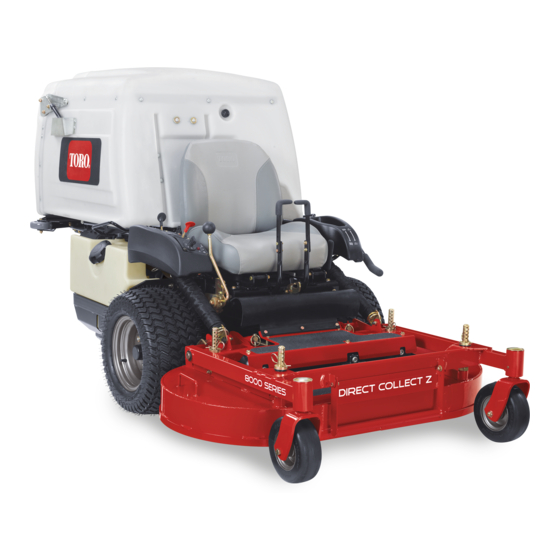
Toro Z Master 8000 Series Operator's Manual
Riding mower with 122cm cutting unit
Hide thumbs
Also See for Z Master 8000 Series:
- Operator's manual (68 pages) ,
- Setup instructions (16 pages) ,
- Installation instructions (2 pages)

Related Manuals for Toro Z Master 8000 Series


Summary of Contents for Toro Z Master 8000 Series
- Page 1 Form No. 3436-620 Rev A Z Master ® 8000 Series Riding Mower with 122cm Cutting Unit Model No. 74311TE—Serial No. 405700000 and Up *3436-620* A Register at www.Toro.com. Original Instructions (EN)
- Page 2 Whenever you need service, genuine Toro parts, or additional information, contact an Authorized Service • Danger indicates an imminently hazardous Dealer or Toro Customer Service and have the model situation which, if not avoided, will result in death and serial numbers of your product ready. Figure 1 or serious injury.
-
Page 3: Table Of Contents
Contents Replacing the Fuel Filter ........40 Servicing the Fuel Tank........40 Electrical System Maintenance ......41 Safety ............... 4 Electrical System Safety ........41 General Safety ........... 4 Servicing the Battery......... 41 Slope Indicator ........... 5 Adjusting the Safety Switches......42 Safety and Instructional Decals ...... -
Page 4: Safety
Safety Disposing of Waste........... 62 Storage ..............63 Storage Safety..........63 This machine has been designed in accordance with Cleaning and Storage ........63 EN ISO 5395. Troubleshooting ............64 Schematics ............. 66 General Safety This product is capable of amputating hands and feet and of throwing objects. -
Page 5: Slope Indicator
Slope Indicator g011841 Figure 3 You may copy this page for personal use. 1. The maximum slope you can operate the machine on is 15 degrees. Use the slope chart to determine the degree of slope of hills before operating. Do not operate this machine on a slope greater than 15 degrees. Fold along the appropriate line to match the recommended slope. -
Page 6: Safety And Instructional Decals
Safety and Instructional Decals Safety decals and instructions are easily visible to the operator and are located near any area of potential danger. Replace any decal that is damaged or missing. decal93-7818 93-7818 decalbatterysymbols 1. Warning—read the Operator's Manual for instructions on Battery Symbols torquing the blade bolt/nut to 115 to 149 N∙m (85 to 110 ft-lb). - Page 7 decal112-9028 112-9028 1. Warning—stay away from moving parts; keep all guards and shields in place. decal116-8934 116-8934 1. Warning—disengage the 2. Height of cut blade clutch, shut off the engine, and remove decal115-4212 the key before making 115-4212 adjustments, servicing, or 1.
- Page 8 decal116-8946 116-8946 1. Rotate counterclockwise 3. Unlock to push the to release. machine. 2. Rotate clockwise to lock. 4. Read the Operator’s decal116-8941 116-8941 Manual before servicing or performing maintenance. 2. 2. Pump-drive belt routing 1. 1. PTO belt routing decal116-9049 116-9049 1.
- Page 9 decal126-4159 Molded in Left Console 1. PTO—disengage 3. Park brake—release 2. PTO—engage 4. Park brake—engage decal126-4207 126-4207 1. Refer to the Operator’s Manual for adjustment procedure. decal130-2880 When PTO is engaged, the idler arm position must be in 130-2880 hatched area or an adjustment is required. 1.
- Page 10 decal126-4158 Molded into Front of Hopper Note: This machine complies with the industry standard stability test in the static lateral and longitudinal tests with the maximum recommended slope indicated on the decal. Review the instructions for operating the machine on slopes in the Operator’s Manual and review the conditions in which you will use the machine to determine whether you can operate the machine in the conditions on that day and at that site.
- Page 11 decal116-9044 116-9044 1. Read the Operator’s Manual before performing any 8. Grease the deck lock mechanism every 100 hours. maintenance. 2. Check the engine oil every 8 hours. 9. Grease the deck pivots every 100 hours. 3. Grease the front caster wheel bearings every 8 hours. 10.
-
Page 12: Product Overview
Key Switch Product Overview The key switch, used to start and shut off the engine, has 3 positions: O , and S . Refer to TART Starting the Engine (page 22). Throttle Control The throttle controls the engine speed, and it has a continuous-variable setting from the S to F position... -
Page 13: Specifications
Contact Engine-Oil-Temperature Light and your Authorized Service Dealer or authorized Toro distributor or go to www.Toro.com for a list of all Buzzer approved attachments and accessories. The engine-oil-temperature light monitors the To ensure optimum performance and continued safety temperature of the engine oil. -
Page 14: Before Operation
Fuel Safety Operation • Fuel is extremely flammable and highly explosive. A fire or explosion from fuel can burn you and Note: Determine the left and right sides of the others and can damage property. machine from the normal operating position. –... -
Page 15: Adding Fuel
Adding Fuel Note: Do not fill the fuel tank completely full. The empty space in the tank allows the fuel to expand. Recommended Fuel • For best results, use only clean, fresh (less than 30 days old), unleaded gasoline with an octane rating of 87 or higher ((R+M)/2 rating method). -
Page 16: Raising The Mower Deck Into The Service Position
Raising the Mower Deck into the Service Position Park the machine on a level surface, disengage the PTO, and engage the parking brake. Shut off the engine, remove the key, and wait for all moving parts to stop before leaving the operating position. -
Page 17: Adjusting The Fill Reduction System (Frs) Baffles
Adjusting the Fill Reduction System (FRS) Baffles The fill reduction system has been designed to allow you to reduce the amount of clippings collected by varying degrees. The advantages include less frequent emptying of the hopper and the return of nutrients to the soil. -
Page 18: Using The Safety-Interlock System
Slightly tighten the locknuts on the rear studs of the FRS baffles. Note: The locknuts on the rear studs may be left slightly loose if you anticipate adjusting the baffle frequently. Install the rubber guard using the attached bolts. Using the Safety-Interlock System g020563 WARNING... -
Page 19: Unlatching The Seat
OFF position, the engine should shut off and the blade should stop. If not, stop using your machine • Use only accessories and attachments approved immediately and contact an Authorized Service by Toro. Dealer. • This machine produces sound levels in excess •... - Page 20 Authorized Service Dealer to inspect the ROPS. • Never raise the mower deck while the blades are • Use only Toro approved accessories and moving. attachments for the ROPS. • Be aware of the mower discharge path and direct the discharge away from others.
-
Page 21: Operating The Parking Brake
Operating the Parking braking and steering. The machine can slide even if the drive wheels are stopped. Brake • Remove or mark obstacles such as ditches, holes, ruts, bumps, rocks, or other hidden hazards. Tall Always engage the parking brake when you stop the grass can hide obstacles. -
Page 22: Operating The Pto-Engagement Lever
Operating the Operating the Throttle PTO-Engagement Lever You can move the throttle control between F positions (Figure 21). The PTO-engagement lever starts and stops the Always use the F position when engaging the PTO. mower blades and blower. Engaging the PTO-Engagement Lever g232776 Figure 21... -
Page 23: Shutting Off The Engine
Engage the parking brake; refer to Engaging the If the choke is in the C position, LOSED Parking Brake (page 21). gradually return choke to the O position as the engine warms up. Move the PTO-engagement lever to the O position (Figure 23). -
Page 24: Driving The Machine
Driving the Machine Adjusting the Height of Cut The throttle control regulates the engine speed as The cutting height of the mower deck is adjusted from measured in rpm (revolutions per minute). Place 2.5 to 10.2 cm (1 to 4 inches) in 6.3 mm (1/4 inch) the throttle control in the F position for best increments. -
Page 25: Emptying The Hopper
It is best to cut only about a third of the grass blade. damaged or worn, replace it immediately with a Cutting more than that is not recommended unless genuine Toro replacement blade. grass is sparse, or it is late fall when grass grows more slowly. -
Page 26: After Operation
Using the Drive-Wheel After Operation Release Valves After Operation Safety WARNING Hands may become entangled in the rotating General Safety drive components below the engine deck, • Shut off the engine, remove the key, and wait which could result in serious injury. for all moving parts to stop before leaving the Shut off the engine, remove the key, and allow operator’s position. -
Page 27: Transporting The Machine
Transporting the Machine Use a heavy-duty trailer or truck to transport the machine. Use a full-width ramp. Ensure that the trailer or truck has all the necessary brakes, lighting, and marking as required by law. Please carefully read all the safety instructions. Knowing this information could help you or bystanders avoid injury. - Page 28 Loading the Machine WARNING Loading a machine onto a trailer or truck increases the possibility of tip-over and could cause serious injury or death. • Use extreme caution when operating a machine on a ramp. • Back the machine up the ramp and drive it forward down the ramp.
-
Page 29: Maintenance
Keep your hands and feet away from moving • To ensure optimum performance, use only parts or hot surfaces. If possible, do not make genuine Toro replacement parts and accessories. adjustments with the engine running. Replacement parts and accessories made by •... - Page 30 • Adjust the caster-pivot bearings. • Check the parking-brake adjustment. • Change the hydraulic filter and reservoir hydraulic fluid when using Toro® HYPR-OIL™ 500 hydraulic fluid (more often in dirty or dusty conditions). • Change the oil in all 3 gearbox housings and add oil as needed.
-
Page 31: Lubrication
Lubrication Greasing the Machine Service Interval: Every 40 hours—Grease the drive shaft (more often in dirty or dusty conditions). Every 100 hours—Grease the mower-deck flip-up pivot (more often in dirty or dusty conditions). Every 100 hours—Grease the mower-deck push-arm tubes (more often in dirty or dusty conditions). -
Page 32: Lubricating The Brake-Handle Pivot
g034251 Figure 32 1. Plate 2. Bolts Lubricate the pump-belt idler arm (Figure 32). Install the plate and the air cleaner. g034248 Figure 30 Lubricating the Shut off the engine, remove the key, and wait Brake-Handle Pivot for all moving parts to stop before leaving the operating position. -
Page 33: Lubricating The Brake-Rod Bushings And Steering-Linkage Rod Ends
Lubricating the Brake-Rod Bushings and Steering-Linkage Rod Ends Service Interval: Every 160 hours Park the machine on a level surface, disengage the PTO, and engage the parking brake. Shut off the engine, remove the key, and wait for all moving parts to stop before leaving the operating position. -
Page 34: Greasing The Caster Pivots
Note: Each of the gearbox sections must be filled separately. Note: Keep the mower deck level to the ground when filling the gearbox with oil. Do not fill the gearbox with the mower deck raised in the service position. Apply a Teflon pipe sealant to the 3 large oil plugs and install them into the gearbox. -
Page 35: Greasing The Caster-Wheel Hubs
Greasing the Caster-Wheel surface of the spacer nut to the end of the axle inside the nut. Hubs Insert the assembled nut and axle into the wheel on the side with the new seal and bearing. Service Interval: Before each use or daily—Grease the front caster wheel hubs (more With the open end of the wheel facing up, fill often in dirty or dusty conditions). -
Page 36: Engine Maintenance
Engine Maintenance Engine Safety • Keep your hands, feet, face, clothing, and other body parts away from the muffler and other hot surfaces. Allow engine components to cool before performing maintenance. • Do not change the engine governor speed or overspeed the engine. -
Page 37: Servicing The Engine Oil
Note: Holes in the filter will appear as bright Remove the dipstick and wipe the oil off. spots. If the filter is damaged, discard it. Insert the dipstick and push it all the way down into the tube. Servicing the Engine Oil Remove the dipstick and read the oil level. - Page 38 Changing the Engine Oil Changing the Engine-Oil Filter Drain the oil from the engine; refer to Changing Note: Dispose of the used oil at a recycling center. the Engine Oil (page 38). Park the machine so that the rear is slightly Change the engine-oil filter (Figure 42).
-
Page 39: Servicing The Spark Plug
Servicing the Spark Plug Installing the Spark Plug Service Interval: Every 200 hours—Check the spark plug(s). Every 500 hours—Replace the spark plug(s). Type: Champion XC12YC Air Gap: 0.76 mm (0.03 inch) Removing the Spark Plug Park the machine on a level surface, disengage the blade-control switch (PTO), and engage the parking brake. -
Page 40: Fuel System Maintenance
Fuel System Maintenance DANGER In certain conditions, fuel is extremely flammable and highly explosive. A fire or explosion from fuel can burn you and others and can damage property. Refer to Fuel Safety (page 14) for a complete list of fuel related precautions. Replacing the Fuel Filter Service Interval: Every 200 hours/Yearly (whichever comes first) (more often in dirty or... -
Page 41: Electrical System Maintenance
Electrical System Slide the red terminal boot off the positive (red) battery terminal and remove the positive (+) Maintenance battery cable (Figure 47). Remove the wing nuts securing the J-hooks (Figure 47). Electrical System Safety Remove the clamp (Figure 47). •... -
Page 42: Adjusting The Safety Switches
Adjusting the Safety Switches Adjust all safety switches so that the plunger extends 4.8 mm to 6.4 mm (3/16 inch to 1/4 inch) from the switch body when the plunger is compressed (Figure 49). g000960 Figure 48 1. Positive (+) battery post 3. -
Page 43: Jump-Starting The Machine
Jump-Starting the Machine vent caps on both batteries. Also ensure that the machines do not touch and that both electrical Check and clean corrosion from the battery systems are off and at the same rated system terminals before jump-starting. Ensure that the voltage. -
Page 44: Drive System Maintenance
Drive System Maintenance Adjusting the Tracking Note: The tracking knob is located under the seat. Note: Rotating this knob allows fine tuning g209397 adjustments so that the machine tracks straight with the drive levers in the full forward position. Run the machine at 3/4 speed for at least 5 minutes to bring hydraulic fluid up to operating temperature. -
Page 45: Checking The Tire Pressure
Checking the Tire Pressure Adjusting the Caster-Pivot Bearings Service Interval: Every 40 hours Maintain the air pressure in the rear tires at 103 kPa Service Interval: Every 500 hours/Yearly (whichever (15 psi). Uneven tire pressure can cause uneven cut. comes first) Check the tires when they are cold, to get the most Park the machine on a level surface, move the accurate pressure reading. -
Page 46: Cooling System Maintenance
Cooling System Maintenance Cooling System Safety • Swallowing engine coolant can cause poisoning; keep out of reach from children and pets. • Discharge of hot, pressurized coolant or touching a hot radiator and surrounding parts can cause severe burns. – Always allow the engine to cool at least 15 minutes before removing the radiator cap. -
Page 47: Servicing The Engine-Oil Cooler
Servicing the Engine-Oil Brake Maintenance Cooler Adjusting the Parking Service Interval: Every 100 hours Brake Park the machine on a level surface, move the speed-control lever to the N position, EUTRAL Service Interval: After the first 100 hours disengage the PTO, and engage the parking Every 500 hours thereafter brake. - Page 48 g020525 Figure 59 1. 22.7 to 23.3 cm (8.92 to 2. Nuts 9.16 inches) Engage and disengage the brakes to check for proper engagement and disengagement. Adjust g020489 Figure 58 if necessary. 1. Parking brake 4. Vertical spring assembly Note: When the brakes are disengaged, there 2.
-
Page 49: Belt Maintenance
Belt Maintenance Inspecting the Belts Service Interval: Every 40 hours Replace the belt if it is worn. The signs of a worn belt include squealing while the belt is rotating; the blades slipping while cutting grass; and frayed edges, burn g006836 marks, and cracks on the belt. -
Page 50: Replacing The Pump-Drive Belt
Adjusting the Belt Guides Engage the PTO lever and check the alignment. Check and adjust the belt guides as stated in Park the machine on a level surface, move the Adjusting the Belt Guides (page 50). speed-control lever to the N position, EUTRAL disengage the PTO, and engage the parking... -
Page 51: Controls System Maintenance
Controls System Engage the parking brake and check the steering levers. Maintenance Repeat steps through until you achieve up to 3 mm (1/8 inch) movement. Adjusting the Reverse-Stop Install the seat frame assembly, if removed in step A. Park the machine on a level surface, move the Adjusting the speed-control lever to the N position,... -
Page 52: Adjusting The Speed-Control Linkage
Adjusting the until the wheels stop or creep slightly in reverse (Figure 66). Speed-Control Linkage Adjust the left pump linkage by rotating the tracking-adjustment knob. WARNING Adjust the right pump linkage by using a wrench to turn the double nuts on the assembly (Figure The engine must be running and the drive 66). -
Page 53: Aligning The Pump-Drive Pulley
Aligning the Pump-Drive disengage the blade-control switch (PTO), and engage the parking brake. Pulley Shut off the engine, remove the key, and wait for all moving parts to stop before leaving the The pump-drive-pulley alignment is necessary for any operating position. of the following conditions: Remove the fuel-tank mounting nuts and swing •... -
Page 54: Adjusting The Pto Brake Spring
Adjusting the PTO Brake Adjusting the Hopper Door Spring Park the machine on a level surface, move the speed-control lever to the N position, EUTRAL Adjust the PTO brake spring only if the blower has disengage the blade-control switch (PTO), and been removed or replaced or if the PTO drive idler engage the parking brake. -
Page 55: Adjusting The Locking-Pin Stop On The Mower Deck
Figure 70 Hydraulic-Fluid 1. Rotate the stop screw clockwise until the locking pin is tight, Specifications then back off 1/2 turn. 2. Loosen the jam nut. Hydraulic Fluid Type: Toro ® HYPR-OIL ™ hydraulic oil or Mobil ® 1 15W-50. -
Page 56: Changing The Hydraulic Fluid And Filter
Install the dipstick. Before installing the new filter, fill it with Toro ® HYPR-OIL ™ 500 hydraulic fluid and apply a thin coat of fluid on the surface of the rubber seal. -
Page 57: Blade Maintenance
Blade Maintenance Blade Safety • Inspect the blades periodically for wear or damage. • Use care when checking the blades. Wrap the blades or wear gloves, and use caution when servicing the blades. Only replace or sharpen the g006530 blades; never straighten or weld them. Figure 72 •... - Page 58 • Replace the blade bolt after striking a foreign object. • Use only genuine Toro replacement g000552 Figure 75 parts. 1. Sharpen at original angle. • Do not lubricate the threads of the...
-
Page 59: Leveling The Mower Deck
• Do not operate up or down a trailer ramp. • Avoid sudden acceleration or deceleration. Important: Do not transport this machine without an approved Toro front mount attachment. Park the machine on a level surface, move the speed-control lever to the N position,... - Page 60 g006788 Figure 78 g233982 1. Spring anchor pin under console Figure 79 2. Secure springs with a washer and hairpin cotter 1. Push arm 3. Slide the spring onto the spring-anchor pin 2. Lynch pin 3. Push-arm tube Remove the spring from the spring anchor. Repeat for other side of the machine.
-
Page 61: Installing The Mower Deck
Pull the mower deck forward to remove it from the machine. Installing the Mower Deck Important: Do not transport the machine without an approved Toro front mount attachment. Park the machine on a level surface, move the speed-control lever to the N position, EUTRAL disengage the blade-control switch (PTO), and engage the parking brake. -
Page 62: Cleaning
Cleaning Cleaning under the Mower Deck Service Interval: Before each use or daily Park the machine on a level surface, move the speed-control lever to the N position, EUTRAL disengage the blade-control switch (PTO), and engage the parking brake. Shut off the engine, remove the key, and wait for all moving parts to stop before leaving the operating position. -
Page 63: Storage
Storage Check the condition of the blades; refer to Servicing the Cutting Blades (page 57). Prepare the machine for storage when non-use Storage Safety occurs over 30 days. Prepare the machine for storage as follows: • Shut off the engine, remove the key, and wait for all moving parts to stop before you leave the Add a petroleum-based operator’s position. -
Page 64: Troubleshooting
Troubleshooting Problem Possible Cause Corrective Action The starter does not crank. 1. The blade-control switch is engaged. 1. Disengage the blade-control switch. 2. The parking brake is disengaged. 2. Engage the parking brake. 3. The motion-control levers are not in 3. - Page 65 Problem Possible Cause Corrective Action The machine pulls to the left or right (with 1. The tracking needs adjustment 1. Adjust the tracking. the motion-control levers fully forward). 2. The tire pressure in the drive tires is 2. Adjust the tire pressure in the drive not correct.
-
Page 66: Schematics
Schematics g020385 Wire Diagram (Rev. A) - Page 67 g020536 Hydraulic Diagram (Rev. A)
- Page 68 The Toro Company (“Toro”) respects your privacy. When you purchase our products, we may collect certain personal information about you, either directly from you or through your local Toro company or dealer. Toro uses this information to fulfil contractual obligations - such as to register your warranty, process your warranty claim or to contact you in the event of a product recall - and for legitimate business purposes - such as to gauge customer satisfaction, improve our products or provide you with product information which may be of interest.
Need help?
Do you have a question about the Z Master 8000 Series and is the answer not in the manual?
Questions and answers