Toro 74314 Operator's Manual

Toro 74314 Operator's Manual

With 42in and 48in cutting unit
Table of Contents

Advertisement

Quick Links

Register at www.Toro.com.
Original Instructions (EN)
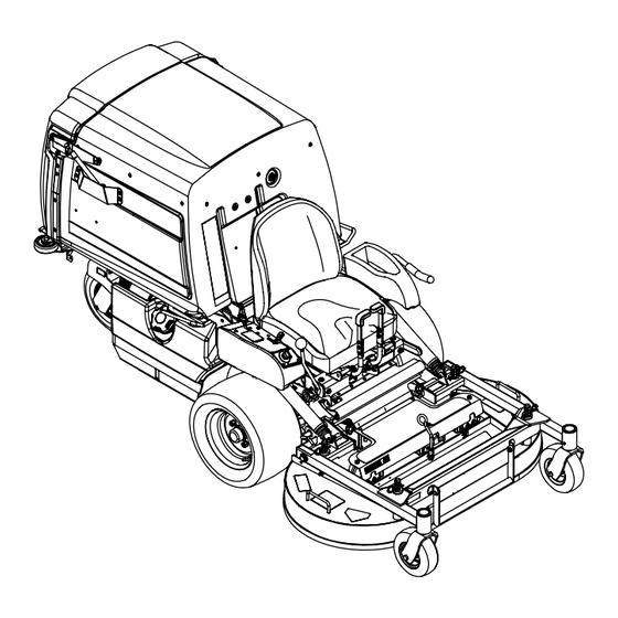
Z Master
®
Mower
With 42in and 48in Cutting Unit
Model No. 74314—Serial No. 400000000 and Up
Model No. 74316—Serial No. 400000000 and Up
Model No. 74318—Serial No. 400000000 and Up
Model No. 74319—Serial No. 400000000 and Up
Form No. 3466-575 Rev A
8000 Series Riding
*3466-575*

Advertisement

Table of Contents
loading
Need help?

Need help?

Do you have a question about the 74314 and is the answer not in the manual?

Questions and answers

Subscribe to Our Youtube Channel

Summary of Contents for Toro 74314

  • Page 1 ® 8000 Series Riding Mower With 42in and 48in Cutting Unit Model No. 74314—Serial No. 400000000 and Up Model No. 74316—Serial No. 400000000 and Up Model No. 74318—Serial No. 400000000 and Up Model No. 74319—Serial No. 400000000 and Up *3466-575* Register at www.Toro.com.
  • Page 2 Authorized Service requirements, the actual engine torque on this class Dealer or Toro Customer Service and have the model of mower will be significantly lower. Please refer to and serial numbers of your product ready.
  • Page 3: Table Of Contents

    Contents Fuel System Maintenance ........42 Servicing the Electronic Fuel-Injection System............42 Safety ............... 4 Replacing the Fuel Filter ........42 Safety Alert Symbol ..........4 Servicing the Fuel Tank........43 General Safety ........... 4 Electrical System Maintenance ......43 Slope Indicator ...........
  • Page 4: Safety

    Safety This machine is capable of amputating hands and feet Safety Alert Symbol and of throwing objects. Toro designed and tested this lawn mower to offer reasonably safe service; however, failure to comply with safety instructions This Safety Alert Symbol...
  • Page 5: Slope Indicator

    Slope Indicator g011841 Figure 3 You may copy this page for personal use. 1. The maximum slope you can operate the machine on is 15 degrees. Use the slope chart to determine the degree of slope of hills before operating. Do not operate this machine on a slope greater than 15 degrees. Fold along the appropriate line to match the recommended slope.
  • Page 6: Safety And Instructional Decals

    Safety and Instructional Decals Safety decals and instructions are easily visible to the operator and are located near any area of potential danger. Replace any decal that is damaged or missing. decal93-7818 93-7818 decalbatterysymbols 1. Warning—read the Operator's Manual for instructions on Battery Symbols torquing the blade bolt/nut to 115 to 149 N∙m (85 to 110 ft-lb).
  • Page 7 decal112-9028 112-9028 1. Warning—stay away from moving parts; keep all guards and shields in place. decal116-8934 116-8934 1. Warning—disengage the 2. Height of cut blade clutch, shut off the engine, and remove decal115-4212 the key before making 115-4212 adjustments, servicing, or 1.
  • Page 8 decal116-8946 116-8946 1. Rotate counterclockwise 3. Unlock to push the to release. machine. 2. Rotate clockwise to lock. 4. Read the Operator’s decal116-8941 116-8941 Manual before servicing or performing maintenance. 2. Pump-drive belt routing PTO belt routing decal116-9049 116-9049 1. Rotating driveline hazard—keep all driveline shields in decal116-8943 116-8943 place.
  • Page 9 Non-EFI Machines Only decal120-0625 120-0625 1. Pinch point, hand—keep hands away. decal126-4207 126-4207 1. Refer to the Operator’s Manual for adjustment procedure. When PTO is engaged, the idler arm position must be in hatched area or an adjustment is required. decal130-2880 130-2880 1.
  • Page 10 EFI Machines Only decal130-2881 130-2881 1. Engine temperature 6. Reverse 2. Fast 7. Retract the piston 3. Slow 8. Extend the piston 4. Neutral 9. Fast 5. Neutral 10. Slow decal126-4159 Molded in Left Console 1. PTO—disengage 3. Park brake—release 2.
  • Page 11 decal126-4158 Molded into Front of Hopper Note: This machine complies with the industry standard stability test in the static lateral and longitudinal tests with the maximum recommended slope indicated on the decal. Review the instructions for operating the machine on slopes in the Operator’s Manual and review the conditions in which you will use the machine to determine whether you can operate the machine in the conditions on that day and at that site.
  • Page 12 decal116-9044 116-9044 1. Read the Operator’s Manual before performing any 8. Grease the deck lock mechanism every 100 hours. maintenance. 2. Check the engine oil every 8 hours. 9. Grease the deck pivots every 100 hours. 3. Grease the front caster wheel bearings every 8 hours. 10.
  • Page 13: Product Overview

    Key Switch Product Overview The key switch, used to start and shut off the engine, has 3 positions: O , and S . Refer to TART Starting the Engine (page 24). Throttle Control The throttle controls the engine speed, and it has a continuous-variable setting from the S to F position...
  • Page 14 Electronic-Control Unit Malfunction-Indicator Light EFI Machines Only The electronic-control unit (ECU) continuously monitors the operation of the EFI system. If a problem or fault within the system is detected, the malfunction-indicator light (MIL) illuminates. The MIL is the red light located in the right console panel.
  • Page 15: Specifications

    To ensure optimum performance and continued safety • Do not operate the mower when people, especially certification of the machine, use only genuine Toro children, or pets are in the area. Stop the machine replacement parts and accessories. Replacement and attachment(s) if anyone enters the area.
  • Page 16 Fuel Safety DANGER In certain conditions during fueling, static Use extreme care when handling fuel. electricity can be released causing a spark which can ignite gasoline vapors. A fire or DANGER explosion from gasoline can burn you and In certain conditions gasoline is extremely others and cause property damage.
  • Page 17: Adding Fuel

    Adding Fuel Note: Do not fill the fuel tank completely full. The empty space in the tank allows the fuel to expand. Recommended Fuel • For best results, use only clean, fresh (less than 30 days old), unleaded gasoline with an octane rating of 87 or higher ((R+M)/2 rating method).
  • Page 18: Raising The Mower Deck Into The Service Position

    Raising the Mower Deck into the Service Position Park the machine on a level surface, disengage the PTO, and engage the parking brake. Shut off the engine, remove the key, and wait for all moving parts to stop before leaving the operating position.
  • Page 19: Adjusting The Fill Reduction System (Frs) Baffles

    Adjusting the Fill Reduction System (FRS) Baffles The fill reduction system has been designed to allow you to reduce the amount of clippings collected by varying degrees. The advantages include less frequent emptying of the hopper and the return of nutrients to the soil.
  • Page 20: Using The Safety-Interlock System

    Slightly tighten the locknuts on the rear studs of the FRS baffles. Note: The locknuts on the rear studs may be left slightly loose if you anticipate adjusting the baffle frequently. Install the PTO guard using the clevis pins and hairpin cotters removed in step 3.
  • Page 21: Unlatching The Seat

    • Move the speed-control lever forward; the The owner/user can prevent and is responsible engine should shut off. for accidents or injuries occurring to himself or herself, other people or property. Unlatching the Seat • This mower was designed for one operator only. Do not carry passengers and keep all others away To unlatch the seat, remove the bolt and the pin on from machine during operation.
  • Page 22 Slope Safety • Never raise the deck with blades running. • • Be aware of the mower discharge path and direct Slopes are a major factor related to loss of control discharge away from others. Avoid discharging and rollover accidents, which can result in severe material against a wall or obstruction as the injury or death.
  • Page 23: Operating The Parking Brake

    Disengaging the Parking Brake • Avoid starting, stopping or turning the machine on slopes. Avoid making sudden changes in speed or direction; turn slowly and gradually. • Do not operate a machine under any conditions where traction, steering or stability is in question. Be aware that operating the machine on wet grass, across slopes or downhill may cause the machine to lose traction.
  • Page 24: Operating The Pto-Engagement Lever

    Operating the Operating the Throttle PTO-Engagement Lever You can move the throttle control between F positions (Figure 20). The PTO-engagement lever starts and stops the Always use the F position when engaging the PTO. mower blades and blower. Engaging the PTO-Engagement Lever g232776 Figure 20...
  • Page 25: Shutting Off The Engine

    Shutting Off the Engine CAUTION Children or bystanders may be injured if they move or attempt to operate the machine while it is unattended. Always remove the key and engage the parking brake when leaving the machine unattended. Disengage the PTO. Move the speed-control lever to the NEUTRAL position.
  • Page 26: Driving The Machine

    Driving the Machine Adjusting the Height of Cut The throttle control regulates the engine speed as The cutting height of the mower deck is adjusted from measured in rpm (revolutions per minute). Place 2.5 to 10.2 cm (1 to 4 inches) in 6.3 mm (1/4 inch) the throttle control in the F position for best increments.
  • Page 27: Emptying The Hopper

    It is best to cut only about a third of the grass blade. damaged or worn, replace it immediately with a Cutting more than that is not recommended unless genuine Toro replacement blade. grass is sparse, or it is late fall when grass grows more slowly.
  • Page 28: After Operation

    Using the Drive-Wheel After Operation Release Valves After Operation Safety WARNING Hands may become entangled in the rotating General Safety drive components below the engine deck, • Park machine on level ground, disengage drives, which could result in serious injury. set parking brake, stop engine, remove key or Shut off the engine, remove the key, and allow disconnect spark plug wire.
  • Page 29: Transporting The Machine

    Transporting the Machine Use a heavy-duty trailer or truck to transport the machine. Use a full-width ramp. Ensure that the trailer or truck has all the necessary brakes, lighting, and marking as required by law. Please carefully read all the safety instructions. Knowing this information could help you or bystanders avoid injury.
  • Page 30 Loading the Machine WARNING Loading a machine onto a trailer or truck increases the possibility of tip-over and could cause serious injury or death. • Use extreme caution when operating a machine on a ramp. • Back the machine up the ramp and drive it forward down the ramp.
  • Page 31: Maintenance

    Unauthorized WARNING modifications to the original equipment or failure to use original Toro parts could lead While maintenance or adjustments are being to serious injury or death. Unauthorized made, someone could start the engine.
  • Page 32: Recommended Maintenance Schedule(S)

    • • Use jack stands to support the machine and/or Keep hands and feet away from moving parts. components when required. If possible, do not make adjustments with the engine running. If the maintenance or adjustment procedure require the engine to be running and CAUTION components moving, use extreme caution.
  • Page 33: Lubrication

    • Adjust the caster-pivot bearings. • Check the parking-brake adjustment. • Change the hydraulic filter and reservoir hydraulic fluid when using Toro® HYPR-OIL™ 500 hydraulic fluid (more often in dirty or dusty conditions). • Change the oil in all 3 gearbox housings and add oil as needed.
  • Page 34: Greasing The Pump-Belt Idler Arm

    g020366 Figure 27 g034248 Figure 28 1. Rear caster pivot 6. Front caster wheel hub 2. PTO-belt idler arm 7. Deck flip-up pivot Shut off the engine, remove the key, and wait 3. Pump-belt idler arm 8. Push-arm tubes for all moving parts to stop before leaving the 4.
  • Page 35: Lubricating The Brake-Handle Pivot

    Lubricating the Brake-Rod Bushings and Steering-Linkage Rod Ends Service Interval: Every 160 hours Park the machine on a level surface, disengage the PTO, and engage the parking brake. Shut off the engine, remove the key, and wait for all moving parts to stop before leaving the operating position.
  • Page 36: Greasing The Caster Pivots

    Pump grease into the fitting until it oozes out around the top bearing. Remove the grease fitting from the hole. Install the hex plug and cap. Greasing the Caster-Wheel Hubs Service Interval: Before each use or daily—Grease the front caster wheel hubs (more g007579 Figure 32 often in dirty or dusty conditions).
  • Page 37: Engine Maintenance

    Engine Maintenance nut and thread it onto the axle with the wrench flats facing outward. Note: Do not thread the spacer nut all of Engine Safety the way onto the end of the axle. Leave approximately 3 mm (1/8 inch) from the outer •...
  • Page 38: Servicing The Engine Oil

    Servicing the Engine Oil Clean the inside of the air-cleaner cover with compressed air. Service Interval: Before each use or daily Gently slide the primary filter out of the Every 100 hours (more often in dirty or dusty air-cleaner body (Figure 34).
  • Page 39 Changing the Engine Oil To keep dirt, grass clippings, etc., out of the engine, clean the area around the oil-fill cap and Note: Dispose of the used oil at a recycling center. dipstick before removing it (Figure 36). Park the machine so that the rear is slightly Remove the dipstick and wipe the oil off.
  • Page 40: Servicing The Spark Plug(S)

    Changing the Engine-Oil Filter Servicing the Spark Plug(s) Drain the oil from the engine; refer to Changing Service Interval: Every 200 hours—Check the spark the Engine Oil (page 39). plug(s). Change the engine-oil filter (Figure 38). Every 500 hours—Replace the spark plug(s). Type for EFI engines: Champion ®...
  • Page 41 Checking the Spark Plug(s) Important: Do not clean the spark plug(s). Always replace the spark plug(s) when it has a black coating, worn electrodes, an oily film, or cracks. If you see light brown or gray on the insulator, the engine is operating properly.
  • Page 42: Checking The Spark Arrester

    Checking the Spark Fuel System Arrester Maintenance For Machines with a Spark DANGER Arrester In certain conditions, fuel is extremely Service Interval: Every 50 hours flammable and highly explosive. A fire or explosion from fuel can burn you and others and can damage property.
  • Page 43: Servicing The Fuel Tank

    Electrical System Shut off the engine, remove the key, and wait for all moving parts to stop before leaving the Maintenance operating position. Allow the machine to cool down. Electrical System Safety Clamp the hose on the fuel tank side of the fuel filter.
  • Page 44: Servicing The Fuses

    Note: Slide the red terminal boot off the positive (red) Do not run the machine with the battery battery terminal and remove the positive (+) disconnected; electrical damage may occur. battery cable (Figure 44). Remove the wing nuts securing the J-hooks (Figure 44).
  • Page 45: Adjusting The Safety Switches

    Adjusting the Safety systems. Make sure that the cables are color coded or labeled for the correct polarity. Switches CAUTION Adjust all safety switches so that the plunger extends Connecting the jumper cables incorrectly 4.8 mm to 6.4 mm (3/16 inch to 1/4 inch) from the switch body when the plunger is compressed (Figure (wrong polarity) can immediately damage...
  • Page 46: Drive System Maintenance

    Drive System Connect the black negative (–) cable to the other terminal (negative) of the booster battery. Maintenance Make the final connection on the engine block of the stalled machine (not to the negative battery post), away from the battery, and stand back Adjusting the Tracking (Figure 48).
  • Page 47: Checking The Tire Pressure

    Checking the Tire Pressure Shut off the engine, remove the key, and wait for all moving parts to stop before leaving the Service Interval: Every 40 hours operating position. Remove the dust cap from the caster and tighten Maintain the air pressure in the rear tires at 103 kPa the locknut until the spring washers are flat, then (15 psi).
  • Page 48: Cooling System Maintenance

    Cleaning the Engine Cooling System Cooling Fins and Shrouds Maintenance Service Interval: Every 100 hours/Yearly (whichever comes first) Cooling System Safety Park the machine on a level surface, move the • Swallowing engine coolant can cause poisoning; speed-control lever to the N position, EUTRAL keep out of reach from children and pets.
  • Page 49: Brake Maintenance

    Brake Maintenance Adjusting the Parking Brake Service Interval: After the first 100 hours Every 500 hours thereafter Make sure that the brake is adjusted properly. Follow this procedure when you remove or replace a brake component. Park the machine on a level surface, move the speed-control lever to the N position, EUTRAL...
  • Page 50: Belt Maintenance

    Belt Maintenance Inspecting the Belts Service Interval: Every 40 hours Replace the belt if it is worn. The signs of a worn belt include squealing while the belt is rotating; the blades slipping while cutting grass; and frayed edges, burn marks, and cracks on the belt.
  • Page 51: Replacing The Pump-Drive Belt

    Engage the PTO lever and check the alignment. Check and adjust the belt guides as stated in Adjusting the Belt Guides (page 52). Replacing the Pump-Drive Belt Park the machine on a level surface, move the g006836 speed-control lever to the N position, EUTRAL Figure 56...
  • Page 52: Adjusting The Belt Guides

    Adjusting the Belt Guides Controls System Maintenance Park the machine on a level surface, move the speed-control lever to the N position, EUTRAL disengage the PTO, and engage the parking brake. Aligning the PTO-Drive Shut off the engine, remove the key, and wait Pulley for all moving parts to stop before leaving the operating position.
  • Page 53: Aligning The Pump-Drive Pulley

    Aligning the Pump-Drive Pulley The pump-drive-pulley alignment is necessary for any of the following conditions: • The engine mounting bolts have been loosened or the engine has been moved or replaced. • The pump pulleys have been loosened, moved, or replaced. •...
  • Page 54: Adjusting The Pto Brake Spring

    Adjusting the PTO Brake Adjusting the Hopper Door Spring Park the machine on a level surface, move the speed-control lever to the N position, EUTRAL Adjust the PTO brake spring only if the blower has disengage the blade-control switch (PTO), and been removed or replaced or if the PTO drive idler engage the parking brake.
  • Page 55: Hydraulic System Maintenance

    1 fluid (more often in dirty or dusty conditions). hydraulic fluid level. Every 500 hours—Change the hydraulic filter Park the machine on a level surface, move the and reservoir hydraulic fluid when using Toro ® speed-control lever to the N position,...
  • Page 56: Mower Deck Maintenance

    Blade Safety introducing contaminates into the system. • Inspect the blades periodically for wear or damage. Before installing the new filter, fill it with Toro ® HYPR-OIL ™ 500 hydraulic fluid and apply a thin •...
  • Page 57 Removing the Blades Replace the blades if they hit a solid object, or if the blade is out of balance or bent. Note: Make note of the red-colored blade position. From the normal user position, it is located on the right side.
  • Page 58: Leveling The Mower Deck

    • Replace the blade bolt after striking a foreign object. • Use only genuine Toro replacement parts. • Do not lubricate the threads of the bolt or spindle before assembly.
  • Page 59: Removing The Mower Deck

    Important: Do not transport this machine without refer to Lowering the Mower Deck to the an approved Toro front mount attachment. Operating Position (page 18). Park the machine on a level surface, move the Note:...
  • Page 60: Installing The Mower Deck

    Loosen the bolts attached to the rubber guard (Figure 72). Important: Do not transport the machine without an approved Toro front mount attachment. Park the machine on a level surface, move the speed-control lever to the N position, EUTRAL disengage the blade-control switch (PTO), and engage the parking brake.
  • Page 61: Adjusting The Locking-Pin Stop On The Mower Deck

    Cleaning Install the springs onto the spring anchor pins under the left and right consoles and secure it with a washer and hairpin cotter (Figure 70). Cleaning under the Mower Unlatch the mower deck from the raised position, slowly lower the mower deck to ground, and Deck lock the deck-locking pins on each side.
  • Page 62: Storage

    Storage Check the condition of the blades; refer to Servicing the Cutting Blades (page 56). Prepare the machine for storage when non-use Storage Safety occurs over 30 days. Prepare the machine for storage as follows: • Shut off the engine, remove the key, and wait for all moving parts to stop before you leave the Add a petroleum based operator’s position.
  • Page 63: Troubleshooting

    Troubleshooting Problem Possible Cause Corrective Action The malfunction-indicator light (MIL) 1. The engine is too hot. 1. Shut off the engine and let it cool. comes on. 2. There is old fuel in the fuel tank. 2. Use new fuel. 3.
  • Page 64 Problem Possible Cause Corrective Action The engine loses power. 1. The engine load is excessive. 1. Reduce the ground speed. 2. The air cleaner is dirty. 2. Clean the air-cleaner element. 3. The oil level in the crankcase is low. 3.
  • Page 65: Schematics

    Schematics g020385 Wire Diagram (Non-EFI machines) (Rev. A)
  • Page 66 g020386 Wire Diagram (EFI machines) (Rev. A)
  • Page 67 g020536 Hydraulic Diagram (Rev. A)
  • Page 68 While the exposure from Toro products may be negligible or well within the “no significant risk” range, out of an abundance of caution, Toro has elected to provide the Prop 65 warnings. Moreover, if Toro does not provide these warnings, it could be sued by the State of California or by private parties seeking to enforce Prop 65 and subject to substantial penalties.

This manual is also suitable for:

Z master 8000 series743167431874319

Table of Contents