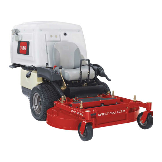
Toro Z Master 8000 Series Operator's Manual
Riding mower with 42in cutting unit
Hide thumbs
Also See for Z Master 8000 Series:
- Operator's manual (68 pages) ,
- Setup instructions (16 pages) ,
- Installation instructions (2 pages)


Need help?
Do you have a question about the Z Master 8000 Series and is the answer not in the manual?
Questions and answers