Table of Contents
Advertisement
Quick Links
Auto-Clean Turbidity System
Home Office
Analytical Technology, Inc.
6 Iron Bridge Drive
Collegeville, PA 19426
Phone: 800-959-0299
610-917-0991
Fax:
610-917-0992
Email: sales@analyticaltechnology.com
O & M Manual
European Office
ATI (UK) Limited
Unit 1 & 2 Gatehead Business Park
Delph New Road, Delph
Saddleworth OL3 5DE
Phone: +44 (0)1457-873-318
Fax:
+ 44 (0)1457-874-468
Email: sales@atiuk.com
Advertisement
Table of Contents

Related Manuals for ATI Technologies Q-Blast Series


Summary of Contents for ATI Technologies Q-Blast Series
- Page 1 O & M Manual Auto-Clean Turbidity System Home Office European Office Analytical Technology, Inc. ATI (UK) Limited 6 Iron Bridge Drive Unit 1 & 2 Gatehead Business Park Collegeville, PA 19426 Delph New Road, Delph Phone: 800-959-0299 Saddleworth OL3 5DE 610-917-0991 Phone: +44 (0)1457-873-318 Fax:...
-
Page 2: Table Of Contents
Table of Contents PART 5 – CALIBRATION ....... 40 PART 1 - INTRODUCTION ........ 4 General ..........4 Turbidity Calibration ......40 Standard System ......... 4 5.11 Cal Zero ......... 40 Features ..........5 5.12 Cal Span ........40 Q46/76 Auto-Clean System Temperature Calibration .... - Page 3 Table of Figures 1 - Q-B ........................... 6 IGURE LAST YSTEM 2 - W ......................10 IGURE OUNT RACKET 4 - Q-B ....................11 IGURE LAST LEANER IMENSIONS 5 - H ....................12 IGURE ANDRAIL OUNTING SSEMBLY 6 - S ........................
-
Page 4: Part 1 - Introduction
Part 1 - Introduction General The Auto-Clean version of the Model Q46/76 is an on-line monitoring system designed for the continuous measurement of turbidity in water and includes an air-blast sensor cleaning system. It is intended for continuous monitoring of raw water, wastewater effluent, or other turbidity applications where sample conditions dictate regular sensor cleaning. -
Page 5: Features
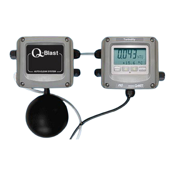
Q46/76 Q-Blast Turbidity Monitor Part 1 - Introduction Features Standard Q46 electronic transmitters are designed to be a fully isolated instruments for operation from either 90-260 VAC or 12-24 VDC power supplies. Two 4-20 mA analog outputs are standard. One output may be configured for PID control, while other output is programmable to track either Turbidity or Temperature. - Page 6 Q46/76 Q-Blast Turbidity Monitor Part 1 - Introduction (System Diagram Shown on Optional Mounting Plate w/Power Distribution Box) Figure 1 - Q-Blast System O&M Manual Rev-H (11/18)
-
Page 7: Q46/76 Auto-Clean System Specifications
Q46/76 Q-Blast Turbidity Monitor Part 1 - Introduction Q46/76 Auto-Clean System Specifications Main Parameter Ranges Manual selection of one of the following display ranges, 0-2.000, 0-20.00, 0-200.0, or 0-2000 NTU Note that the values above 400 on the 0-2000 display range are not valid Power 90 - 260 VAC, 50/60 Hz., 10 VA Maximum... -
Page 8: Q46/76 Performance Specifications
Q46/76 Q-Blast Turbidity Monitor Part 1 - Introduction Q46/76 Performance Specifications Accuracy 0.5% of range or 0.03 NTU Repeatability 0.3% of range or 0.02 NTU Sensitivity 0.1% of selected range Non-linearity 0.1% of selected range Warm-up Time 30 seconds to rated performance (electronics only) Supply Voltage Effects ±... -
Page 9: Part 2 - Analyzer Mounting
Part 2 – Analyzer Mounting General The Q46 Auto-Clean pH System consists of two assemblies housed in NEMA 4X (IP-66) enclosures. The analyzer electronics and the Q-Blast cleaner assembly should both be mounted near the sensor location, with a maximum of 30 feet between the monitor/cleaner and the sensor. The standard system is supplied with a 30 ft. -
Page 10: Wall Mount Dimensions
Part 2 – Analyzer Mounting Q46/76 Q-Blast Turbidity Monitor Figure 2 - Wall/Pipe Mount Bracket Wall Mount Dimensions Figure 3 shows the dimensions of the analyzer dimensions. Note that the enclosure mounting brackets are not installed at the factory. They are supplied separately and must be attached using the screws provided. - Page 11 Part 2 – Analyzer Mounting Q46/76 Q-Blast Turbidity Monitor Figure 3 - Wall Mount Analyzer Dimensions Figure 3 - Q-Blast Cleaner Dimensions O&M Manual Rev-H (11/18)
-
Page 12: Railing Mount
Part 2 – Analyzer Mounting Q46/76 Q-Blast Turbidity Monitor Railing Mount Figure 5 shows the optional mounting assembly (on system mounting plate) used to mount the analyzer and cleaner assembly to a typical safety handrail that surrounds many aeration tanks. This bracket assembly consists of vertical channels attached to the handrail with u-bolts. -
Page 13: Sensor Assembly
Part 2 – Analyzer Mounting Q46/76 Q-Blast Turbidity Monitor Sensor Assembly The turbidity sensor is contained in a housing that acts as a light shield and also directs the cleaning air across the face of the sensor. Figure 6 shows an exploded view of that assembly. The sensor is already installed in the Autoclean holder when shipped from the factory. -
Page 14: Sensor Installation
Part 2 – Analyzer Mounting Q46/76 Q-Blast Turbidity Monitor Sensor Installation Applications for Auto-Clean turbidity monitoring are done using a submersible sensor. Submersible sensors are mounted to a 1" pipe using a standard 1" PVC thread by thread pipe coupling. The mounting pipe can be secured to standard 1½” or 2” pipe rail using a mounting bracket kit available from ATI (part number 00-0624) as shown in Figure 7 &... - Page 15 Part 2 – Analyzer Mounting Q46/76 Q-Blast Turbidity Monitor Figure 7 - Sensor Mounting Detail O&M Manual Rev-H (11/18)
-
Page 16: Part 3 - Electrical Installation
Part 3 – Electrical Installation General Q46 Auto-Clean analyzers and Q-Blast cleaners are powered from 90-260 VAC, 50/60 Hz. or 12- 24 VDC. Systems can draw up to 0.5 amps when the internal air compressor activates as part of the sensor cleaning system. Normal current draw is less than 0.2 amps when the cleaner is off. Important Notes: Use wiring practices that conform to all national, state and local electrical codes. - Page 17 Part 3 – Electrical Installation Q46/76 Q-Blast Turbidity Monitor Figure 8 - Electrical Connections O&M Manual Rev-H (11/18)
- Page 18 Part 3 – Electrical Installation Q46/76 Q-Blast Turbidity Monitor Figure 9 - Q-blast Connections O&M Manual Rev-H (11/18)
-
Page 19: Sensor Wiring
Part 3 – Electrical Installation Q46/76 Q-Blast Turbidity Monitor Sensor Wiring Sensor connections are made to a terminal block mounted on the front section of the monitor. The sensor cable can be quickly connected to the Q46 terminal strip by matching the wire colors on the cable to the color designations on the label in the monitor. -
Page 20: Q-Blast To Q46 Connection
Part 3 – Electrical Installation Q46/76 Q-Blast Turbidity Monitor Q-Blast to Q46 Connection Connections inside the Q-Blast enclosure include power and an interconnect cable running to the Q46 monitor. To access the terminal compartment, loosen the 4 screws holding the cover in place and set the cover aside. - Page 21 Part 3 – Electrical Installation Q46/76 Q-Blast Turbidity Monitor Figure 11 - Electrical Connections O&M Manual Rev-H (11/18)
- Page 22 Part 3 – Electrical Installation Q46/76 Q-Blast Turbidity Monitor Figure 12 - Q-Blast Connections w/Optional J-Box O&M Manual Rev-H (11/18)
-
Page 23: Analog Output Connections
Part 3 – Electrical Installation Q46/76 Q-Blast Turbidity Monitor Analog Output Connections Q46 Auto-Clean systems provide two 4-20 mA outputs. Output connections are made to terminal TB1 as shown in Figure 8. Relay Connections Relay wiring is done to terminal blocks inside the Q46 display assembly. This unit actually contains three SPDT relays, and a bank of three low-power relays that is used to control the activation of the sensor automatic cleaning system. -
Page 24: Part 4 - Configuration
Part 4 – Configuration User Interface The user interface for the Q46 Series instrument consists of a custom display and a membrane keypad. All functions are accessed from this user interface (no internal jumpers, pots, etc.). When power is first applied, you may notice that the display does not come on immediately. This is normal. -
Page 25: 4.11 Keys
Part 5 – Configuration Q46/76 Q-Blast Turbidity Monitor 4.11 Keys All user configurations occur through the use of four membrane keys. These keys are used as follows: MENU/ESC To scroll through the menu section headers or to escape from anywhere in software. -
Page 26: Software
Q46/76 Q-Blast Turbidity Monitor Part 5 - Configuration Icon Area The icon area contains display icons that assist the user in set-up and indicate important states of system functions. The CAL, CONFIG, and DIAG icons are used to tell the user what branch of the software tree the user is in while scrolling through the menu items. -
Page 27: 4.21 Software Navigation
Q46/76 Q-Blast Turbidity Monitor Part 5 - Configuration 4.21 Software Navigation Within the CAL, CONFIG, CONTROL, and DIAG menu sections is a list of selectable items. Once a menu section (such as CONFIG) has been selected with the MENU key, the user can access the item list in this section by pressing either the ENTER key or the UP arrow key. - Page 28 Q46/76 Q-Blast Turbidity Monitor Part 5 - Configuration Start MENU M ENU M ENU M ENU M ENU M ENU MEASURE CONFIG CONTROL DIAG SECTIONS (display only) ENTER ENTER ENTER ENTER Temperature PID 0% #1 Entry Lock Set Hold Cal Span % Signal PID 100% #1 Cal Temp...
-
Page 29: Measure Menu [Measure]
Q46/76 Q-Blast Turbidity Monitor Part 5 - Configuration 4.22 Measure Menu [MEASURE] The default menu for the system is the display-only menu MEASURE. This menu is a display-only measurement menu, and has no changeable list items. When left alone, the instrument will automatically return to this menu after approximately 30 minutes. -
Page 30: Calibration Menu [Cal]
Q46/76 Q-Blast Turbidity Monitor Part 5 - Configuration The MEASURE screens are intended to be used as a very quick means of looking up critical values during operation or troubleshooting. 4.23 Calibration Menu [CAL] The calibration menu contains items for frequent calibration of user parameters. There are five items in this list: Cal Span, Cal Temp, Cal Zero, Cal Signal, and Set Range. - Page 31 Q46/76 Q-Blast Turbidity Monitor Part 5 - Configuration effective air-blast system that is self contained in the A/C enclosure. When enabled, the D, E and F relay settings are not displayed in the CONFIG or CNTRL menus. Com Mode Sets digital communication mode of analyzer. Optional digital communication card must be plugged into the power supply slot for this function to work.
-
Page 32: Control Menu [Control]
Q46/76 Q-Blast Turbidity Monitor Part 5 - Configuration Temp Units This function sets the display units for temperature measurement. Press ENTER to initiate user entry mode, and the entire value will flash. Use the UP arrow key to modify the desired display value. The choices are °F and °C. - Page 33 Q46/76 Q-Blast Turbidity Monitor Part 5 - Configuration PID Deriv Derivative is a second order implementation of Integral, used to suppress “second-order” effects from process variables. These variables may [Iout1=PID] include items like pumps or mixers that may have minor impacts on the measured value.
- Page 34 Q46/76 Q-Blast Turbidity Monitor Part 5 - Configuration and the LCD indicator illuminates when the turbidity value exceeds the setpoint. When the phase is LO, the relay energizes and the LCD indicator illuminates when the turbidity drops below the setpoint. The failsafe setting does have an impact on this logic.
- Page 35 Q46/76 Q-Blast Turbidity Monitor Part 5 - Configuration Figure 17 shown below is a visual description of a typical alarm relay application. When value rises to ≥ 1.000 ppm, relay When value falls to < 1.000 ppm, relay closes, until value falls back to < 0.950 ppm. closes, until rises back to >...
-
Page 36: Diagnostics Menu [Diag]
Q46/76 Q-Blast Turbidity Monitor Part 5 - Configuration To change the values for Timer CYCLE, CLEAN, and HOLD, press ENTER to initiate user entry mode, and entire value will flash. Use the UP arrow key to modify the desired value. Selections for each variable are: CLEAN 1-10 minutes, CYCLE 1-999 hours, HOLD 0-999 minutes. - Page 37 Q46/76 Q-Blast Turbidity Monitor Part 5 - Configuration Fault List The Fault List screen is a read-only screen that allows the user to display the cause of the highest priority failure. The screen indicates the number of faults present in the system and a message detailing the highest priority fault present.
- Page 38 Q46/76 Q-Blast Turbidity Monitor Part 5 - Configuration Fail Out #1 This function enables the user to define a specified value that the main current output will go to under fault conditions. When the Relay Option Board is installed, the display will read Fail Out #1. When enabled to ON, the output may be forced to the current value set in Fail Val (next item.) With the Fail Out setting of ON, and a Fail Val setting of 6.5 mA, any alarm condition will cause the current loop output to drop outside the...
- Page 39 Q46/76 Q-Blast Turbidity Monitor Part 5 - Configuration may displace the forced air stream, and a good saturation reading may be difficult to obtain. *Failsafe This function allows the user to set the optional system relays to a failsafe condition. In a failsafe condition, the relay logic is reversed so that the relay is electrically energized in a normal operating state.
-
Page 40: Part 5 - Calibration
Part 5 – Calibration Turbidity Calibration Turbidity monitors will start to measure aqueous samples as soon as power is applied and the sensor is submerged in a tank, channel, or sample chamber. Calibration of a turbidity system is normally required at start-up, but factory settings are likely to be fairly accurate, so it is often OK to start up the monitor without adjustment. -
Page 41: Temperature Calibration
Q46/76 Q-Blast Turbidity Monitor Part 6 - Calibration Mixing a turbidity standard takes 24 hours. First, place 5 cc. of Turbidity Standard 1 and 5 cc. of Turbidity Standard 2 in a 100 cc volumetric flask. Allow to stand for 24 hours at about 25 C. Then dilute to 100 cc. - Page 42 Q46/76 Q-Blast Turbidity Monitor Part 6 - Calibration Scroll to the CAL menu section using the MENU key and press ENTER or the UP arrow key. Press the UP arrow key until Cal Temp is displayed. Press the ENTER key. The message Place sensor in solution then press ENTER will be displayed.
-
Page 43: Part 6 - Sensor Auto-Clean System
Part 6 - Sensor Auto-Clean System General The cleaner control system located in the cleaner enclosure contains a number of components designed to supply pulses of high pressure air to the tip of the sensor. The main components and their function are as follows: Compressor: The air compressor is a small DC powered diaphragm type compressor that delivers air at up to 30 PSI to the accumulator cylinder which is part of the system. -
Page 44: Cleaner Programming
Part 6 – Sensor Auto-Clean System Q46/76 Q-Blast Turbidity Monitor The cleaner can be started manually any time the monitor is in operation. From the Measure Menu, press the UP arrow until the bottom line of the display indicates “Tcycle xx Hrs”. Then press and hold the ENTER key for about 3 seconds to start the cleaning cycle. -
Page 45: Part 7 - Pid Controller Details
Part 7 – PID Controller Q46/76 Q-Blast Turbidity Monitor Part 7 – PID Controller Details PID Description PID control, like many other control schemes, is used in chemical control to improve the efficiency of chemical addition or control. By properly tuning the control loop that controls chemical addition, only the amount of chemical that is truly required is added to the system, saving money. - Page 46 Part 7 – PID Controller Q46/76 Q-Blast Turbidity Monitor The most notable feature of the algorithm is the fact the proportional gain term affects all components directly (unlike some other algorithms - like the “series” form.) If a pre-existing controller utilizes the same form of the algorithm shown above, it is likely similar settings can for made if the units on the settings are exactly the same.
-
Page 47: Classical Pid Tuning
Part 7 – PID Controller Q46/76 Q-Blast Turbidity Monitor Classical PID Tuning Unlike many high speed position applications where PID loops are commonly used, the chemical feed application employed by this instrument does not require intense mathematical exercise to determine tuning parameters for the PID. In fact, the risk of instability is far greater with overly tuned PID control schemes. - Page 48 Part 7 – PID Controller Q46/76 Q-Blast Turbidity Monitor The easiest process’ to control with closed-loop schemes are generally linear, and symmetrical, in nature. For example, controlling level in tank where the opening of valve for a fixed period of time corresponds linearly to the amount that flows into a tank.
-
Page 49: Part 8 - System Maintenance
Part 8 – System Maintenance General The Q46/76 Turbidity Monitor will generally provide unattended operation over long periods of time. With proper care, the system should continue to provide measurements indefinitely. For reliable operation, maintenance on the system must be done on a regular schedule. Keep in mind that preventive maintenance on a regular schedule is much less troublesome than emergency maintenance that always seems to come at the wrong time. -
Page 50: Part 9 - Troubleshooting
Part 9 – Troubleshooting General The information included in this section is intended to be used in an attempt to quickly resolve an operational problem with the system. During any troubleshooting process, it will save the most time if the operator can first determine if the problem is related to the analyzer, sensor, or some external source. -
Page 51: Analyzer
Q46/76 Q-Blast Turbidity Monitor Part 9 - Troubleshooting moving wiring, or by adding very inexpensive snubbers (such As Quencharcs) to the load. Carefully examine any junction box connections for loose wiring or bad wire stripping. If possible, connect the sensor directly to the analyzer for testing. Check sensor for fouling. -
Page 52: Display
Q46/76 Q-Blast Turbidity Monitor Part 9 - Troubleshooting 9.31 Display Messages The Q46 Series instruments provide a number of diagnostic messages which indicate problems during normal operation and calibration. These messages appear as prompts on the secondary line of the display or as items on the Fault List. MESSAGE DESCRIPTION POSSIBLE CORRECTION... -
Page 53: Spare Parts
Spare Parts Part No. Description 07-0378 AC Powered monitor electronics assembly, 100-240 VAC 07-0379 DC Powered monitor electronics assembly 12-24 VDC 07-0380 AC Powered monitor electronics assembly w/Profibus, 100-240 VAC 07-0381 DC Powered monitor electronics assembly w/Profibus, 12-24 VDC 03-0445 Q46T Front Lid electronics assembly 03-0407 Q46 P/S Assy, 100-240VAC... - Page 54 PRODUCT WARRANTY Analytical Technology, Inc. (Manufacturer) warrants to the Customer that if any part(s) of the Manufacturer's equipment proves to be defective in materials or workmanship within the earlier of 18 months of the date of shipment or 12 months of the date of start-up, such defective parts will be repaired or replaced free of charge.
- Page 55 WATER QUALITY MONITORS GAS DETECTION PRODUCTS Dissolved Oxygen Ammonia Carbon Monoxide Free Chlorine Hydrogen Combined Chlorine Nitric Oxide Total Chlorine Oxygen Residual Chlorine Dioxide Cl2 Phosgene Potassium Permanganate Bromine Chlorine Dissolved Ozone Chlorine Dioxide pH/ORP Fluorine Conductivity Iodine Hydrogen Peroxide Acid Gases Peracetic Acid O Ethylene Oxide...
Need help?
Do you have a question about the Q-Blast Series and is the answer not in the manual?
Questions and answers