
Related Manuals for Fronius FOH 8-40


Summary of Contents for Fronius FOH 8-40
- Page 1 / Perfect Welding / Solar Energy / Perfect Charging Translated document: FOH 8-40 Operating Instructions, Maintenance FOH 10-76 Open weld head FOH 20-114 FOH 40-168 42,0426,0234,EN V06 - 06092018...
- Page 3 Dear reader, Introduction These operating instructions will help you familiarise yourself with the machine. It is in your interest to read these instructions carefully and to observe the directions contained in them. This will prevent faults and incorrect operation or possible damage to installed components.
- Page 5 Contents General information Safety rules ..............................11 General remarks............................11 Proper use ..............................11 Environmental conditions ......................... 12 Obligations of the operator ........................12 Obligations of the personnel ........................12 Mains connection ............................. 12 Protecting yourself and others ......................... 13 Information on noise emission values ......................
- Page 6 Replacing the plastic coupling ........................64 Technical data Technical data ............................... 67 Open weld head FOH 8-40 ........................67 Open weld head FOH 10-76 ........................67 Open weld head FOH 20-114 ........................67 Open weld head FOH 40-168 ........................67 Orbital welding torch ..........................
- Page 7 Spare parts, circuit diagram Spare parts ..............................73 Spare parts, wearing parts and auxiliary materials .................. 73 Ordering details ............................73 FOH 8-40..............................74 FOH 10-76..............................77 FOH 20-114 .............................. 80 FOH 20-114 .............................. 81 FOH 20-114 .............................. 82 FOH 40-168.............................. 83 Orbital welding torch TTWO 2000 F++ .....................
- Page 9 General information...
- Page 11 Safety rules General remarks The device is manufactured using state-of-the-art technology and according to r ecognised safety standards. If used incorrectly or misused, however, it can cause: injury or death to the operator or a third party, damage to the device and other material assets belonging to the operator, inefficient operation of the device.
- Page 12 Environmental Operation or storage of the device outside the stipulated area will be deemed as not in conditions accordance with the intended purpose. The manufacturer shall not be held liable for any damage arising from such usage. Ambient temperature range: during operation: -10 °C to + 40 °C (14 °F to 104 °F) during transport and storage: -20 °C to +55 °C (-4 °F to 131 °F) free from dust, acids, corrosive gases and substances, etc.
- Page 13 Protecting your- Persons involved with welding expose themselves to numerous risks, e.g.: self and others arc radiation, which can damage eyes and skin hazardous electromagnetic fields, which can endanger the lives of those using cardiac pacemakers risk of electrocution from mains current and welding current greater noise pollution harmful welding fumes and gases Anyone working on the workpiece whilst welding is taking place must wear suitable pro-...
- Page 14 Dangers posed An electric shock is potentially life threatening and can be fatal. by mains cur- Do not touch live parts either inside or outside the device. rent and welding During TIG welding, the welding wire, the wirespool, the feed rollers and all pieces of current metal that are in contact with the welding wire are live.
- Page 15 EMC measures In certain cases, even though a device complies with the standard limit values for emissions, it may affect the application area for which it was designed (e.g. when there is sensitive equipment at the same location, or if the site where the device is installed is close to either radio or television receivers).
- Page 16 Specific hazards Keep hands, hair, clothing and tools away from moving parts. For example: Fans Cogs Wirespools and welding wires ► Do not reach into the rotating cogs of the wire drive or into rotating drive components. ► Covers and side panels may only be opened or removed for as long as maintenance or repair work is being carried out.
- Page 17 Danger from Shielding gas cylinders contain gas under pressure and can explode shielding gas if damaged. As shielding gas cylinders form part of the welding equipment, cylinders they must be handled with great care. Protect shielding gas cylinders containing compressed gas from excessive heat, mechanical impact, slag, naked flames, sparks and arcs.
- Page 18 Safety measures Only operate the device if all safety devices are fully functional. If the safety devices are in normal opera- not fully functional, there is a risk of tion injury or death to the operator or a third party, damage to the device and other material assets belonging to the operator, inefficient operation of the device.
- Page 19 Copyright of these operating instructions remains with the manufacturer. Text and illustrations were accurate at the time of printing. Fronius reserves the right to make changes. The contents of the operating instructions shall not provide the basis for any claims whatsoever on the part of the purchaser.
- Page 20 Copyright Copyright of these operating instructions remains with Fronius International GmbH. Text and illustrations were accurate at the time of printing. Fronius reserves the right to make changes. The contents of the operating instructions shall not provide the basis for any claims whatsoever on the part of the purchaser.
- Page 21 General remarks Principle The open weld heads in the FOH series are devices with an open design and are pow- ered by 24 V direct current motors. An exceptional speed control is achieved by using a completely maintenance-free and indestructible encoder. Device concept The open weld heads in the FOH series are intended for welding butt welds (PG, PF &...
- Page 23 Safety...
- Page 25 No modifications or upgrades to the open weld head should therefore be undertaken without first consulting FRONIUS International GmbH and obtaining written approval. Duty to provide Before they start work, the device operator must instruct or train all persons working with...
- Page 26 Operating The operating instructions help you to use the open weld head safely and efficiently and instructions must be accessible at all times. The various sections of the operating instructions must always be kept near the device. Clearly mark the place where the instructions are kept Ensure that all persons using the open weld head know where the operating instructions are located.
- Page 27 Operational safety regulation Spare parts, Using spare parts and wearing parts from third-party manufacturers may pose risks. Use wearing parts Fronius original replacement parts only. and auxiliary The manufacturer cannot accept any liability for damage resulting from the use of spare materials or wearing parts or auxiliary materials that are not approved by the manufacturer.
- Page 28 Danger points and safety precautions General During arc welding you can incur injury and cause harm to other people. For this reason, always adhere to the applicable safety and accident prevention regulations, including when orbital welding. Safety instruc- WARNING! tions Risk of burns from hot surfaces.
- Page 29 Safety instruc- WARNING! tions Risk of skin injuries or burns due to hot weldments. (continued) The residual heat generated during welding can heat up components to extremely high temperatures. Falling components can lead to burns and severe injuries to feet. Wear welding footwear when inserting and removing compo- nents.
- Page 31 Description of the open weld heads...
- Page 33 Scope of supply Open weld head configuration FOH open weld head Plug-in control line (6 m) Transport case with foam insert and removable trolley system Wearing parts box TTWO 2000 F++ (option) Accessories Wearing parts box TTWO 2000 F++ (48,0100,0041) Extension hosepack FCH/FOH 10 m (38,0100,0440)
- Page 34 Accessories FOH wire support (continued) (58,0913,7000) Balancer spring return 6-10 kg, lifting length 2 m (48,0005,1033) Balancer spring return 14-18 kg, lifting length 2 m (48,0005,1035)
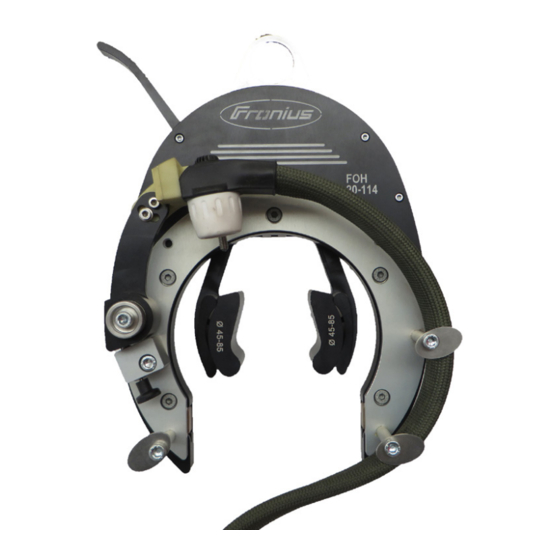
- Page 35 Open weld head components FOH open weld head (10) (11) Attachment eyelet Head Tool carrier Torch arm Torch holder TIG welding torch Handle with drive unit Clamping system Reducing jaw (10) Fastening screws for reducing jaw (11) Hosepack holder...
- Page 36 Hosepack for FOH open weld head Control line for the open weld head (open weld head end). Control line for the open weld head (control unit end). Combined welding current and shielding gas connection. Water cooling connection on torch head.
- Page 37 Controls and connections Connections Forming gas Welding gas Open weld head control line Connection cable between open weld head and control unit/power source. Wirefeeder connection cable For controlling the wire exit speed at the open weld head. Wirefeed Grounding cable TIG welding torch FRC-FPA 3030 remote control with 10-metre cable...
- Page 38 Controls for open weld head Controls for open weld head (front) (1) Clamping lever For fixing (and releasing) the open weld head to the workpiece to be welded. (2) Torch height adjuster and scanner For setting the torch height above the workpiece. (3) Angle lock for torch holder For setting the tilt angle of the torch head.
- Page 39 Controls for open weld head (continued) Controls for open weld head (rear) (6) Connecting plug for the motor control cable For suppling and controlling the open weld head. (7) Adjusting screw for clamping system For setting the clamping jaws to the respective pipe diameter.
- Page 40 Welding position Welding position Horizontal position on rigid pipe Possible welding positions: PG (fixed pipe, horizontal welding axis, vertical-down welding position) PF (fixed pipe, horizontal welding axis, vertical-up welding position) Vertical position on rigid pipe Possible welding positions: PC (fixed pipe, vertical welding axis, transverse welding position)
- Page 41 Commissioning...
- Page 43 Starting up the open weld head Positioning the Connect the control cable for the open weld head drive motor. on the workpiece Open the quick-release lever and place on the workpiece. Set the clamping jaws ► Pre-adjust the clamping jaws to the desired pipe external diameter.
- Page 44 Positioning the ► Allow the torch arm to drop open weld head slowly down onto the component on the workpiece until the torsion spring is press- (continued) ing it against the component. The spring and the torch height adjuster ensures a constant distance to the pipe is main- tained.
- Page 45 Positioning the Wall thickness Electrode spacing open weld head on the workpiece 0.5 mm - 1.0 mm 0.8 mm (continued) 1.25 mm - 2.0 mm 1.3 mm 2.25 mm - 3.9 mm 1.8 mm With cold wire 2.5 - 3.5 mm allowance Setting the Using the external wirefeed it is possible to precisely set the position of the welding wire...
- Page 46 Setting the Tilt angle external wirefeed Undo the fixing screw to adjust the tilt an- (continued) gle of the holder. Once the desired value has been set, the fixing screw must be retightened. Free length of wire The free length of wire at the wire exit can be adjusted by undoing the fixing screw.
- Page 47 Threading the WARNING! welding wire Risk of injury from welding wire springing back! Carelessness or using the equipment incorrectly can cause injury to the hands, face or other parts of the body. Keep a firm hold of the end of the welding wire when threading it into the 4-roller drive.
- Page 48 Threading the 1. Push the welding wire through the welding wire motor plate until it reaches the exit (continued) opening of the cold-wire wirefeeder. 2. Fold back down the pressure lever holding the two upper feed rollers. 3. Fold up the lock mechanisms until they noticeably engage.
- Page 49 Operation...
- Page 51 Before welding Safety WARNING! Danger of injury from premature arc ignition. The arc may be ignited accidentally. This can cause serious eye injuries. Before operating the open weld head, ensure that welding is not switched on by mistake in the system control program. Checking the Check all connections between the individual components before starting up the open connections...
- Page 52 Selecting the To select an orbital open weld head, type of orbital call up the "Orbital open weld head" open weld head menu in the main menu of the control system. Select the desired type of orbital open weld head (a) Open orbital open weld head (b) Closed orbital open weld head (c) Manual welding torch...
- Page 53 Welding process Creating a 1. Open the "Parameter settings" menu. program The parameter settings allow the user to enter or correct the most important welding parameters for the orbital welding process. 2. Create the welding program based on the requirements for the weld seam and the workpiece in the parameter settings menu.
- Page 54 Starting the 5. The open weld head begins to execute welding process the set welding program. The hose- (continued) pack is wound up automatically by the control system's welding program NOTE! Ensure that the hose- pack is being guided correctly while it is being wound up.
- Page 55 After the welding process Removing the Pull back the torch arm until the lock open weld head engages, taking care not to damage the hosepack in the process. Open the clamping piece at the quick-release lever and remove.
- Page 57 Troubleshooting, maintenance and disposal...
- Page 59 Troubleshooting In the event of faults, note that the functioning of the entire system depends on many General additional components (power source, wirefeeder, etc.) that are also potential sources of problems. When an error occurs, the corresponding error message appears either on the system control display or on the display of the power source.
- Page 60 Troubleshooting Errors Cause Remedy (continued) Speed is not being regulated - Faulty pulse generator Replace pulse generator Electronic error in the Replace motor control unit Replace motor control board Electrode does not move Grounding cable Check grounding cable back up after making contact missing Check connections Electronic fault...
- Page 61 Maintenance Maintenance WARNING! personnel Risk of injury and damage from incorrectly performed maintenance work. It is essential to adhere to the maintenance intervals and maintenance proce- dures. The manufacturer accepts no liability for any damage caused by inade- quate or poorly performed maintenance. All maintenance work on the open weld head must only be carried out by trained and qualified personnel.
- Page 62 Opening the NOTE! The manufacturer shall not be liable for any damage that arises due welding head to improper handling. The following are suggestions that cannot be used as the basis of any claims whatsoever for defects that arise subsequently. Use an Allen key (4 mm) to unscrew the retaining bolts of the tool carrier.
- Page 63 Opening the Remove all gear wheels. welding head Clean the inside of the head. (continued) Remove all grease residues. Check the gear wheels and shim rings for damage and replace if necessary. Apply new roller bearing grease to the inside of the head. Re-install all gear wheels in the head.
- Page 64 Replacing the Use an Allen key (3 mm) to plastic coupling unscrew the retaining bolts of the drive motor. Pull the drive motor out of the housing. Remove the faulty coupling. Fit the new coupling to the drive motor. Push the drive motor back into the housing.
- Page 65 Technical data...
- Page 67 Technical data Open weld head Weight (without hosepack) 1.87 kg (4.12 lbs) FOH 8-40 Power supply 24 V DC Torch type TTGO F++ Hosepack length Welding position PC, PF, PG Open weld head Weight (without hosepack) 2.39 kg (5.27 lbs)
- Page 68 185 mm 400 mm Rating plates NOTE! The rating plates may not be removed or modified without the consent of Fronius International GmbH. Ensure that the rating plates remain legible. FOH 8 - 40 FOH 10 - 76 Art.No.: 8,044,201 Art.No.:...
- Page 69 Environmental Operation or storage of the system outside the stipulated area will be deemed as not conditions in accordance with the intended purpose. The manufacturer shall not be held liable for any damage arising from such usage. Ambient temperature range: during operation: +5 °C to +40 °C (41 °F to 104 °F) during transport and storage: -20 °C to +55 °C (-4 °F to 131 °F) Relative humidity:...
- Page 71 Spare parts, circuit diagram...
- Page 73 Spare parts Spare parts, Using spare parts and wearing parts from third-party manufacturers may pose risks. Use wearing parts Fronius original replacement parts only. and auxiliary The manufacturer cannot accept any liability for damage resulting from the use of spare materials or wearing parts or auxiliary materials that are not approved by the manufacturer.
- Page 74 FOH 8-40 Art.Nr: 8,044,201...
- Page 75 FOH 8-40 Art.Nr: 8,044,201 Pos. Quantity Article number Description 48,0005,2202 Component assembly drive shaft Drive shaft Pin4x3.5 48,0005,2143 Gear-wheel Z30 48,0005,2206 Component assembly gear-wheel 48,0005,2091 Gear-wheel Z40 48,0005,2203 Ball-bearing_3x10x4 48,0005,2204 Cylinder pin 3m6x8_(DIN6325) 48,0005,2092 Gear-wheel Z20 Component assembly clamping system...
- Page 76 FOH 8-40 Art.Nr: 8,044,201 Pos. Quantity Article number Description Component assembly TIG torch mini 48,0005,2222 TIG torch mini water-cooled 48,0005,2223 Gas cup mini 48,0005,2224 Back cap 48,0005,2225 Teflon torch insulator 20x8x1.5mm 48,0005,2226 Clamp sleeve 1.6x16mm 48,0005,2227 Clamp sleeve 2.4x16mm 48,0005,2228 Gas lense mini 1.6mm...
- Page 77 FOH 10-76 Art.Nr: 8,044,202...
- Page 78 FOH 10-76 Art.Nr: 8,044,202 Pos. Quantity Article number Description Component assembly drive shaft 48,0005,2202 Drive shaft Pin4x3.5 48,0005,2143 Gear-wheel Z30 48,0005,2254 Component assembly gear-wheel 48,0005,2111 Gear-wheel Z30 48,0005,2203 Ball-bearing_3x10x4 48,0005,2204 Cylinder pin 3m6x8_(DIN6325) 48,0005,2092 Gear-wheel Z20 Component assembly clamping system 48,0005,2255 48,0005,2256 Clamping system housinig base...
- Page 79 FOH 10-76 Art.Nr: 8,044,202 Pos. Quantity Article number Description Individual parts 48,0005,2266 Body 48,0005,2123 Cover 48,0005,2124 Rotor 48,0005,2231 Ball-bearing DIN 625_8x22x7 48,0005,2104 Clutch (POM) 48,0005,2232 Locking pin 2x18 DIN 1481 48,0005,2233 Screw M3x8 (DIN 912) 48,0005,2105 Hanger loop 48,0005,2234 Countersunk screw M3x6 (DIN 7991) 48,0005,2235 Insolator adapter 48,0005,2106...
- Page 80 FOH 20-114 Art.Nr: 8,044,203...
- Page 81 FOH 20-114 Art.Nr: 8,044,203 Pos. Quantity Article number Description 48,0005,2202 Component assembly drive shaft Drive shaft Pin4x3.5 48,0005,2143 Gear-wheel Z30 48,0005,2272 Component assembly gear-wheel 48,0005,2091 Gear-wheel Z40 48,0005,2203 Ball-bearing_3x10x4 48,0005,2204 Cylinder pin 3m6x8_(DIN6325) 48,0005,2111 Gear-wheel Z30 Component assembly clamping system 48,0005,2273 48,0005,2274 Clamping system housinig base...
- Page 82 FOH 20-114 Art.Nr: 8,044,203 Pos. Quantity Article number Description Individual parts 48,0005,2280 Body 48,0005,2281 Cover 48,0005,2139 Rotor 48,0005,2231 Ball-bearing DIN 625_8x22x7 48,0005,2104 Clutch (POM) 48,0005,2232 Locking pin 2x18 DIN 1481 48,0005,2233 Screw M3x8 (DIN 912) 48,0005,2105 Hanger loop 48,0005,2234 Countersunk screw M3x6 (DIN 7991) 48,0005,2235 Insolator adapter 48,0005,2106...
- Page 83 FOH 40-168 Art.Nr: 8,044,204...
- Page 84 FOH 40-168 Art.Nr: 8,044,204 Pos. Quantity Article number Description Component assembly drive shaft 48,0005,2202 Drive shaft Pin4x3.5 48,0005,2143 Gear-wheel Z30 48,0005,2285 Component assembly gear-wheel 48,0005,2091 Gear-wheel Z40 48,0005,2203 Ball-bearing_3x10x4 48,0005,2204 Cylinder pin 3m6x8_(DIN6325) Component assembly clamping system 48,0005,2286 48,0005,2287 Clamping system housinig base 48,0005,2288 Insert clamping system 48,0005,2289...
- Page 85 FOH 40-168 Art.Nr: 8,044,204 Pos. Quantity Article number Description Individual parts 48,0005,2293 Body 48,0005,2152 Cover 48,0005,2153 Rotor 48,0005,2231 Ball-bearing DIN 625_8x22x7 48,0005,2104 Clutch (POM) 48,0005,2232 Locking pin 2x18 DIN 1481 48,0005,2233 Screw M3x8 (DIN 912) 48,0005,2105 Hanger loop 48,0005,2234 Countersunk screw M3x6 (DIN 7991) 48,0005,2235 Insolator adapter 48,0005,2106...
- Page 86 Orbital welding torch TTWO 2000 F++ Wire adjustment unit FOH 58,0913,7000...
- Page 87 Wire feeding Orbital TTWO 2000 Extension hose pack FCH / FOH 10m 38,0100,0440...
- Page 88 Motor control Quantity Article number Description cable 1.3.1610FOH Motor control cable FOH, 6m 10-pole cable gland on weld head side, 14-pin cable connector on controller side Transport case 48,0005,2426...
- Page 89 Using spare parts and wearing parts from third-party manufacturers may pose risks. parts ► Use Fronius original replacement parts only. ► The manufacturer cannot accept any liability for damage resulting from the use of spare or wearing parts or auxiliary materials that are not approved by the manufac- turer.
- Page 90 Content of wearing parts 42,0001,4656 48,0009,0436 (continued) 42,0001,4679 48,0009,0437 48,0009,0438 42,0001,4681 48,0009,0439 48,0009,0441 Article number Quantity Description 48,0100,0041 Wear part box TTWO 2000 F++ 48,0005,2187 Wear part box (empty) 42,0001,1150 Clamping sleeve 2,4/ø5,3x12,7 42,0001,1151 Clamping sleeve 3,2/ø5,3x12,7 42,0001,4295 Clamping sleeve case M10x1/M8x1 2,4 42,0001,4296 Clamping sleeve case M10x1/M8x1 3,2 42,0001,4297...
- Page 91 Circuit diagrams FOH 10-40, FOH 40-168...
- Page 92 FOH 10-76, FOH 20-114...
- Page 93 EU Declaration of conformity...
- Page 94 FRONIUS INTERNATIONAL GMBH TechSupport Automation www.fronius.com www.fronius.com/addresses...
Need help?
Do you have a question about the FOH 8-40 and is the answer not in the manual?
Questions and answers