Fronius FK 5000 MV Operating Instructions Manual
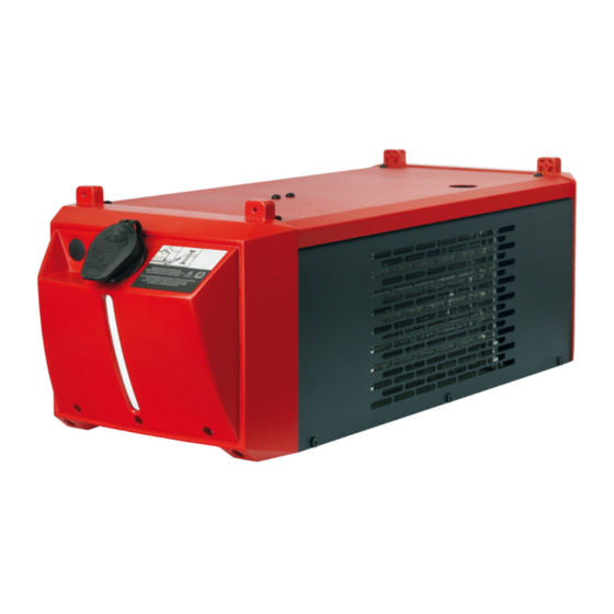
Cooling unit
Hide thumbs
Also See for FK 5000 MV:
- Operating instructions/spare parts list (60 pages) ,
- Operating instructions manual (60 pages)
Table of Contents
Advertisement
Quick Links
Advertisement
Table of Contents

Related Manuals for Fronius FK 5000 MV


Summary of Contents for Fronius FK 5000 MV
- Page 1 FK 5000 Operating instructions FK 5000 MV Cooling unit 42,0426,0079,EN 012009...
- Page 3 Read the manual carefully and you will soon be familiar with all the many great features of your new Fronius product. This really is the best way to get the most out of all the advantages that your machine has to offer.
-
Page 5: Table Of Contents
Validity of „General Delivery and Payment Conditions“ ................19 Troubleshooting ............................20 Service codes displayed on the wire-feed unit ..................20 FK 5000 / FK 5000 MV ........................... 20 Tightening the coolant pump shaft ......................21 Technical data ............................. 23 General .............................. -
Page 6: General
5 l coolant Four 5x25mm self-tapping screws Operating instructions Field of applicati- The FK 5000 / FK 5000 MV cooling unit can be used for: water-cooled MIG/MAG manual welding torches water-cooled MIG/MAG machine welding torches water-cooled MIG/MAG robot welding torches... -
Page 7: Warning Notices Affixed To The Device
Warning notices A number of safety symbols can be seen on the cooling unit rating plate. The safety affixed to the symbols must NOT be removed or painted over. The symbols warn against operating the device equipment incorrectly, as this may result in serious injury and damage. Do not dispose of used cooling units with domestic waste. -
Page 8: Options
Options General The options listed below are available for all cooling unit variants. Return tempera- Return temperature monitoring: ture and flow A temperature sensor monitors the return temperature of the coolant. monitoring If the coolant temperature exceeds 75 °C, the sensor interrupts the welding current. The wire-feed unit outputs the error message „hot | H2O“. -
Page 9: Control Elements And Connections
Control elements and connections Front (1) (2) No. Function Water flow connection blanking cover (black) Water return connection blanking cover (red) Screw cap for coolant container Operation and maintenance instruc- tions Coolant inspection window Rear No. Function Power source connecting plug Rating plate Water flow connection (black) Water return connection (red) -
Page 10: Fitting The Cooling Unit To The Trolley
Fitting the cooling unit to the trolley General The welding system can be fitted to a PickUp 5000 trolley to make the system (incl. cooling unit) more mobile. Important! If the welding system is not equipped with an auto-transformer, the cooling unit must be installed right at the bottom. -
Page 11: Installation
Installation Connecting the WARNING! An electric shock can be fatal. If the power source is connected to cooling unit and the mains electricity supply during installation, there is a high risk of very se- the power source rious injury and damage. Only carry out work on the device when - the power source mains switch is in the - O - position, - the power source is unplugged from the mains. -
Page 12: Connecting The Interconnecting Hosepack To The Cooling Unit
Connecting the interconnecting hosepack to the cooling unit... -
Page 13: Before Commissioning
The cooling unit is delivered empty. The coolant is supplied separately in a 5 l canister. the coolant Fill the cooling unit with coolant before commissioning the unit. Use only original Fronius coolant (item no. 40,0009,0046) when filling the cooling unit. Other coolants are not recommended for electrical conductivity and compatibility reasons. Guarantee provi- The coolant pump may only be used with original coolant supplied by the manufacturer. -
Page 14: Utilisation In Accordance With „Intended Purpose
Utilisation in The device is intended exclusively for cooling Fronius hosepacks and welding torches. accordance with „intended purpo- The cooling unit is to be used exclusively for its intendedpurpose. se“ Utilisation for any other purpose, or in any other manner, shall be deemed to be „not in accordance with the intended purpose“. -
Page 15: Putting The Cooling Unit Into Service
Putting the cooling unit into service General The cooling unit is powered from the power source. If the power source mains switch is turned to position - I -, the cooling unit will also start to operate. Filling the coo- NOTE! If the cooling unit is being ling unit filled with coolant for the first... -
Page 16: Putting The Cooling Unit Into Service
Bleeding the cooling unit (continued) Putting the NOTE! The coolant level and cooling unit into cleanliness of the coolant must service always be checked before star- ting the cooling unit. NOTE! During welding, check at regular intervals that the coolant is flowing through properly. -
Page 17: Care, Maintenance And Disposal
NOTE! If water-cooled torches are operated without coolant, this will normally result in a fault in the torch body or hosepack. Fronius shall not be liable for any damage resulting from such action. In addition, no warranty claims will be... -
Page 18: Once A Week
Check coolant level and cleanliness. If the coolant level is below the „min“ mark, top up with coolant. NOTE! Use only original Fronius coolant (40,0009,0046) when filling cooling units. Other coolants are not recommended for electrical conductivity and compatibility reasons. - Page 19 Important! Coolant must not be disposed of in the public sewage system. NOTE! Use only original Fronius coolant (item no. 40,0009,0046) when refilling the cooling unit. WARNING! An electric shock can be fatal. Before restarting the cooling unit,...
-
Page 20: Every 6 Months - In 3-Shift Operation
Every 6 months - in 3-shift operati- (continued) Bleed the cooling unit CAUTION!! Danger of scalding by hot coolant. Never bleed the cooling unit until it has been allowed to cool down. -
Page 21: Every 12 Months
Important! Coolant must not be disposed of in the public sewage system. NOTE! Use only original Fronius coolant (item no. 40,0009,0046) when refilling the cooling unit. WARNING! An electric shock can be fatal. Before restarting the cooling unit,... - Page 22 Every 12 months (continued) Bleed the cooling unit CAUTION!! Danger of scalding by hot coolant. Never bleed the cooling unit until it has been allowed to cool down.
-
Page 23: Service Life Of The Coolant Pump
With regard to cooling units, the „General Delivery and Payment Conditions“ shown in ral Delivery and the price list only apply under the following conditions: Payment Conditi- ons“ Max. 8 hrs/day operation (single-shift operation) Original Fronius coolant used exclusively (item number 40,0009,0046 or 40,0009,0075) Regular maintenance and regular change of coolant... -
Page 24: Troubleshooting
Troubleshooting Service codes hot | H2O displayed on the The optional cooling unit temperature sensor has tripped. wire-feed unit Cause: Coolant temperature too high Remedy: Wait until the end of the cooling phase, i.e. until „hot | H2O“ is no longer displayed. -
Page 25: Tightening The Coolant Pump Shaft
FK 5000 / FK High operating noise level 5000 MV Cause: Coolant level too low (continued) Remedy: Top up coolant Cause: Coolant pump defective Remedy: Contact service team The welding torch becomes very hot Cause: The design dimensions of the torch are not sufficient for this task Remedy: Observe the duty cycle and loading limits Cause:... -
Page 26: Technical Data
Flow rate Q (l/min) The flow rate Q depends on the length of the interconnecting hosepack and the diameter of the hose. FK 5000, FK 5000 FK 5000 MV FK 5000 MV Mains voltage 400 V AC 200-230/400-480 V AC... - Page 27 Ersatzteilliste Schaltplan Spare Parts List Circuit Diagram Liste de pièces de rechange Schéma de connexions Lista parti di ricambio Schema Lista de repuestos Esquema de cableado Lista de peças sobresselentes Esquema de conexões Onderdelenlijst Bedradingsschema Reservdelsliste Koblingsplan Seznam náhradních dílů Schéma zapojení...
- Page 28 4,048,001 FK 5000 42,0401,1119 (4x) 4,048,001,630 FK 5000 MV 42,0401,1118 (2x) BU2,0201,2972 option - 4,100,604 BU2,0201,2973 BU2,0201,2974 43,0009,0052 43,0001,1084 42,0401,1118 (6x) option - 4,100,612 44,0001,1145 43,0001,1131 42,0402,0236 42,0405,0186 - RED 42,0201,0105 42,0405,0187 - BLACK 44,0001,1398 42,0401,0962 44,0001,1238 44,0001,1253 42,0405,0694 43,0006,0223...
- Page 29 FK 5000...
- Page 30 FK 5000 MV...
- Page 31 FRONIUS INTERNATIONAL GMBH Buxbaumstraße 2, A-4600 Wels, Austria Tel: +43 (0)7242 241-0, Fax: +43 (0)7242 241-3940 E-Mail: sales@fronius.com www.fronius.com www.fronius.com/addresses Under http://www.fronius.com/addresses you will find all addresses of our Sales & service partners and Locations. ud_fr_st_so_00082 012008...
Need help?
Do you have a question about the FK 5000 MV and is the answer not in the manual?
Questions and answers