Fronius FK 5000 Operating Instructions Manual
Cooling unit
Hide thumbs
Also See for FK 5000:
- Operating instructions manual (31 pages) ,
- Operating instructions/spare parts list (60 pages)
Table of Contents
Advertisement
Quick Links
Advertisement
Table of Contents
Troubleshooting

Related Manuals for Fronius FK 5000


Summary of Contents for Fronius FK 5000
- Page 1 Perfect Welding / Perfect Charging / / Solar Energy Operating Instructions FK 5000, FK 5000 MV Cooling unit 42,0426,0079,EN 032-25052020 Fronius prints on elemental chlorine free paper (ECF) sourced from certified sustainable forests (FSC).
- Page 3 Thank you for the trust you have placed in our company and congratulations on buying this high-quality Fronius product. These instructions will help you familiarise yourself with the product. Reading the instructions carefully will enable you to learn about the many different features it has to offer.
-
Page 5: Table Of Contents
Contents Safety rules ..............................General ..............................Proper use ............................Environmental conditions........................Obligations of the operator........................Obligations of personnel ........................Mains connection ..........................Protecting yourself and others ......................Noise emission values .......................... Danger from toxic gases and vapours ....................Danger from flying sparks ........................Risks from mains current and welding current.................. - Page 6 Care, maintenance and disposal ....................... Safety..............................General ..............................Symbols for care and maintenance of the cooling unit ................. Maintenance intervals, maintenance work.................... Gas purging the cooler.......................... Changing the coolant ..........................Disposal ..............................Technical data Technical data............................General ..............................FK 5000, FK 5000 MV ..........................
-
Page 7: Safety Rules
Safety rules General The device is manufactured using state-of-the-art technology and according to recognised safety standards. If used incorrectly or misused, however, it can cause: injury or death to the operator or a third party, damage to the device and other material assets belonging to the operating company, inefficient operation of the device. -
Page 8: Obligations Of The Operator
Ambient temperature range: during operation: -10 °C to + 40 °C (14 °F to 104 °F) during transport and storage: -20 °C to +55 °C (-4 °F to 131 °F) Relative humidity: up to 50% at 40 °C (104 °F) up to 90% at 20 °C (68 °F) The surrounding air must be free from dust, acids, corrosive gases or substances, etc. -
Page 9: Noise Emission Values
Suitable protective clothing must be worn when working with the device. The protective clothing must have the following properties: Flame-resistant Insulating and dry Covers the whole body, is undamaged and in good condition Safety helmet Trousers with no turn-ups Protective clothing refers to a variety of different items. Operators should: Protect eyes and face from UV rays, heat and sparks using a protective visor and reg- ulation filter Wear regulation protective goggles with side protection behind the protective visor... -
Page 10: Danger From Flying Sparks
The following components are responsible, amongst other things, for the degree of toxicity of welding fumes: Metals used for the workpiece Electrodes Coatings Cleaners, degreasers, etc. Welding process used The relevant material safety data sheets and manufacturer's specifications for the listed components should therefore be studied carefully. -
Page 11: Meandering Welding Currents
The electrode (rod electrode, tungsten electrode, welding wire, etc.) must never be immersed in liquid for cooling Never touch the electrode when the power source is switched on. Double the open circuit voltage of a power source can occur between the welding elec- trodes of two power sources. -
Page 12: Emc Device Classifications
EMC Device Clas- Devices in emission class A: sifications Are only designed for use in industrial settings Can cause line-bound and radiated interference in other areas Devices in emission class B: Satisfy the emissions criteria for residential and industrial areas. This is also true for residential areas in which the energy is supplied from the public low-voltage mains. -
Page 13: Specific Hazards
Specific hazards Keep hands, hair, clothing and tools away from moving parts. For example: Fans Cogs Rollers Shafts Wirespools and welding wires Do not reach into the rotating cogs of the wire drive or into rotating drive components. Covers and side panels may only be opened/removed while maintenance or repair work is being carried out. -
Page 14: Requirement For The Shielding Gas
Odourless and colourless shielding gas may escape unnoticed if an adapter is used for the shielding gas connection. Prior to assembly, seal the device-side thread of the adapter for the shielding gas connection using suitable Teflon tape. Requirement for Especially with ring lines, contaminated shielding gas can cause damage to equipment and the shielding gas reduce welding quality. -
Page 15: Safety Measures At The Installation Location And During Transport
Safety measures A device toppling over could easily kill someone. Place the device on a solid, level surface at the installation such that it remains stable location and dur- The maximum permissible tilt angle is 10°. ing transport Special regulations apply in rooms at risk of fire or explosion Observe relevant national and international regulations. -
Page 16: Commissioning, Maintenance And Repair
Cooling Liquid FCL 10/20 does not ignite. The ethanol-based coolant can ignite under cer- tain conditions. Transport the coolant only in its original, sealed containers and keep well away from any sources of ignition. Used coolant must be disposed of properly in accordance with the relevant national and international regulations. -
Page 17: Data Protection
Fronius International GmbH hereby declares that the device is compliant with Directive 2014/53/EU. The full text on the EU Declaration of Conformity can be found at the following address: http://www.fronius.com Devices marked with the CSA test mark satisfy the requirements of the relevant standards for Canada and the USA. -
Page 19: General
General... -
Page 21: General
Two versions of the cooling unit are available: FK 5000 (basic version) FK 5000 MV (Multivoltage version) The FK 5000 MV adapts itself automatically to the mains voltage. The Multivoltage version is available only from the factory. Scope of supply... -
Page 22: Information About The Coolant
Information about CAUTION! the coolant Danger from using non-permitted coolant. This can result in serious damage to property. ► Only use coolant available from the manufacturer. ► Do not mix different coolants. ► When changing the coolant, make sure all the coolant is replaced. ►... -
Page 23: Warning Notices On The Device
The symbols warn against operating the equipment incorrectly, as this may result in serious injury and damage. Part No.: www.fronius.com Ser.No.: IEC 60 974-2/-10 Cl.A IP 23 400 V 0.7 A... -
Page 24: Options
Options General The options listed below are available for all cooling unit variants. Coolant tempera- Coolant temperature monitoring and flow monitoring are parts of an installation set and ture monitoring cannot be ordered separately. and flow monitor- Coolant temperature monitoring A temperature sensor monitors the coolant return temperature during welding. -
Page 25: Connections And Mechanical Components
Connections and mechanical compo- nents... -
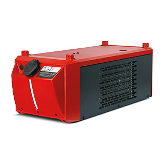
Page 27: Connections And Mechanical Components
Connections and mechanical components Connections and mechanical com- (1) (2) ponents Part No.: www.fronius.com Ser.No.: IEC 60 974-2/-10 Cl.A IP 23 400 V 0.7 A 50 Hz 0.42 MPa (4.2 bar) 1.0 kW 1l/min (8) (9) Front of cooling unit... -
Page 29: Installation And Commissioning
Installation and commissioning... -
Page 31: Before Installation And Commissioning
Before installation and commissioning Safety WARNING! Danger due to incorrect operation and incorrectly performed work. This can result in severe personal injury and damage to property. ► All the work and functions described in this document must only be carried out and used by trained and qualified personnel. -
Page 32: Information About The Coolant
Information about The cooling unit is delivered empty. the coolant Use only original Fronius coolant (Cooling Liquid FCL 10/20 or torch coolant) when filling the cooling unit. Other coolants are not recommended for electrical conductivity and mate- rial compatibility reasons. -
Page 33: Fitting The Cooling Unit To The Trolley
Fitting the cooling unit to the trolley General The welding system can be fitted to a trolley to make the system (incl. cooling unit) more mobile. CAUTION! Risk due to work that has been carried out incorrectly. This can result in serious damage to property ►... -
Page 34: Connecting The Cooling Unit To The Power Source
Connecting the cooling unit to the power source Safety WARNING! Danger from electric current. An electric shock can be fatal. ► Before starting the work described below: ► Turn the power source mains switch to the "O" position. ► Disconnect the power source from the mains. ►... -
Page 36: Connect The Coolant Hoses To The Cooling Unit
Connect the coolant hoses to the cooling unit Safety WARNING! Danger from electric current. An electric shock can be fatal. ► Turn the power source mains switch to the "O" position. ► Disconnect the power source from the mains. ► Ensure that the power source remains disconnected from the mains until all work has been completed. -
Page 37: Filling And Starting Up The Cooling Unit
Filling and starting up the cooling unit Filling the cooling WARNING! unit Danger from electric current. An electric shock can be fatal. ► Turn the power source mains switch to the "O" position. ► Disconnect the power source from the mains. ►... -
Page 38: Commissioning The Cooling Unit
Commissioning NOTE! the cooling unit Before starting up the cooling unit, first check that it contains an adequate amount of coolant and that the coolant is clean and uncontaminated. NOTE! During welding, check at regular intervals that the coolant is flowing properly. You should be able to see a steady return flow of coolant into the coolant container. -
Page 39: Fitting The Coolant Filter Option
Fitting the coolant filter option Safety WARNING! Danger from electric current. An electric shock can be fatal. ► Turn the power source mains switch to the "O" position. ► Disconnect the power source from the mains. ► Ensure that the power source remains disconnected from the mains until all work has been completed. -
Page 41: Troubleshooting
Troubleshooting... -
Page 43: Troubleshooting
Troubleshooting Safety WARNING! Danger due to work that has been carried out incorrectly. This can result in serious injury and damage to property. ► All the work described below must only be carried out by trained and qualified person- nel. ►... - Page 44 Insufficient or no coolant flow Cause: Coolant level too low Remedy: Top up coolant Cause: Constriction or foreign body in cooling circuit Remedy: Remove constriction or foreign body Cause: Coolant contaminated Remedy: Change the coolant Cause: Coolant filter (option) misplaced when connecting coolant return Remedy: Clean coolant filter/replace filter element Cause:...
-
Page 45: Displayed Service Codes
The welding torch becomes very hot Cause: The specification of the cooling unit is inadequate Remedy: Observe the duty cycle and loading limits Cause: The specification of the welding torch is inadequate Remedy: Observe the duty cycle and loading limits Cause: Inadequate coolant flow Remedy:... -
Page 46: Twisting The Coolant Pump Shaft
Twisting the coolant pump shaft Safety WARNING! Danger due to work that has been carried out incorrectly. This can result in severe personal injury and damage to property ► All the work described below must only be carried out by trained and qualified person- nel. -
Page 47: Care, Maintenance And Disposal
Care, maintenance and disposal... -
Page 49: Care, Maintenance And Disposal
Care, maintenance and disposal Safety WARNING! Danger due to work that has been carried out incorrectly. All the work described below must only be carried out by trained and qualified personnel. ► Fully read and understand this document. ► Fully read and understand all the Operating Instructions for the system components, especially the safety rules. -
Page 50: Symbols For Care And Maintenance Of The Cooling Unit
Fronius shall not be liable for any damage resulting from such action. In addition, no warranty claims will be entertained. Ensure that all the hosepacks, the welding torch and the ground earth connection are undamaged Check that there is an all-round clearance of 0.5 m (1 ft... -
Page 51: Gas Purging The Cooler
Every 2 months If present: check the coolant filter for dirt and clean it/re- place the filter element if necessary Every 6 months Gas purge the cooler Every 6 months Gas purge the cooler for 3-shift opera- Change the coolant tion with ethanol- based coolant Every 12 months... -
Page 52: Changing The Coolant
NOTE! The coolant must not be disposed of in the public sewage system. Dispose of coolant in accordance with the applicable local and national regulations. NOTE! Use only original Fronius coolant when refilling the cooling unit. - Page 53 NOTE! Seal off the coolant hose as soon as it is pulled out of the coolant pump connec- tion. This will ensure that as little coolant as pos- sible enters the device. Immediately remo- ve any coolant that enters the device or spills onto its exterior.
- Page 54 Ensure that all hose connections are properly established and are not leaking...
-
Page 55: Disposal
Ensure that there is no coolant inside the device or on its exterior Disposal Dispose of in accordance with the applicable national and local regulations. -
Page 57: Technical Data
Technical data... -
Page 59: Technical Data
Ambient temperature Delivery head Flow rate Q (l/min) - The flow rate Q depends on the length of the interconnecting hosepack and the diameter of the hose. FK 5000, FK 5000 FK 5000 FK 5000 MV Mains voltage 400 V AC... - Page 60 FRONIUS INTERNATIONAL GMBH Froniusstraße 1 A-4643 Pettenbach AUSTRIA contact@fronius.com www.fronius.com Under www.fronius.com/contact you will find the addresses of all Fronius Sales & Service Partners and locations.